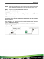
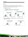
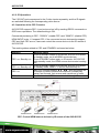
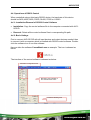
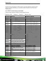
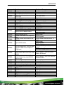
1
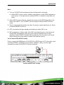
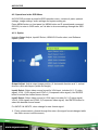
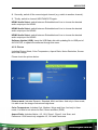
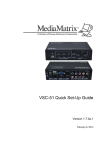
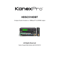
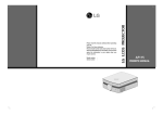
AVG-SC51D
Features
The AVG-SC51D is a compact mini scaler
switcher with 5 video inputs (3 HDMI, 2 VGA)
and 6 audio inputs (3 HDMI audio & 2 VGA
audio; 1 MIC audio input). The VGA input
supports VGA, YPbPr and C-video, assuring
the scaler switcher is compliant with multiple
video signal types.
Compliant with HDCP
Supports CEC, with commands to
enable/disable this function
Supports video source auto-switching
function
Bi-directional IR & RS232 control
Output resolutions selectable to assure
preferred output, supports various
output resolutions, such as 1920x1200,
1920x1080, 1600x1200, 1360x768,
1280x800, 1280x720, 1024x768
VGA video supports C-video, YPbPr
and VGA
Supports online software upgrades
48V phantom power to support
condenser microphone
MIC port supports balanced/unbalanced
signals.
3-level MIC input, supports condenser
microphone, dynamic microphone and
wireless microphone
Controllable via button, IR & RS232
Extensive OSD function
AVG-SC51D
PLEASE READ THIS PRODUCT MANUAL CAREFULLY
BEFORE USING THIS PRODUCT.
This manual is only for operation instruction only, and
not to be used in a maintenance capacity. The
functions described in this version are current as at
March 2015. Any changes of functions and
operational parameters will be updated in future
manual versions. Please refer to your dealer for the
latest product details.
Version 1.0 1/3/15
AVG-SC51D
SAFETY OPERATION GUIDE
In order to guarantee the reliable operation of the equipment and safety of the
user, please abide by the following procedures in installation, use and
maintenance:
1. The system must be earthed properly. Please do not use two blade plugs
and ensure the alternating power supply ranges from 100v to 240v and from
50Hz to 60Hz.
2. Do not install the switcher in an environment where it will be exposed to
extreme hot or cold temperatures.
3. This unit will generate heat during operation, please ensure that you allow
adequate ventilation to ensure reliable operation.
4. Please disconnect the unit from mains power if it will be left unused for a
long time.
5. Please DO NOT try to open the casing of the equipment, DO NOT attempt to
repair the unit. Opening the unit will void the warranty. There are high
voltage components in the unit and attempting to repair the unit could result
in serious injury.
6. Do not allow the unit to come into contact with any liquid as that could result
in personal injury and product failure.
AVG-SC51D
TABLE OF CONTENTS
Introduction .............................................................................................................. 1
Introduction to AVG-SC51D ......................................................................... 1.1
Features ....................................................................................................... 1.2
What’s in the Box.......................................................................................... 1.3
Product Appearance ................................................................................................ 2
AVG-SC51D Front Panel .............................................................................. 2.1
AVG-SC51D Rear Panel .............................................................................. 2.2
System Connection .................................................................................................. 3
Usage Precautions ....................................................................................... 3.1
System Diagram ........................................................................................... 3.2
Connection Procedure .................................................................................. 3.3
Microphone Connection ................................................................................ 3.4
Application .................................................................................................... 3.5
System Operations................................................................................................... 4
Operation of Front Panel Buttons ................................................................. 4.1
Resolution Adjusting ....................................................................... 4.1.1
Switching Operations ...................................................................... 4.1.2
Volume Adjusting ............................................................................ 4.1.3
Used in OSD Menu ......................................................................... 4.1.4
Software updating: .......................................................................... 4.1.5
Operations of IR ........................................................................................... 4.2
IR Remote....................................................................................... 4.2.1
IR Operations.................................................................................. 4.2.2
Operation of the CEC Function..................................................................... 4.3
Operations of RS232 Control........................................................................ 4.4
Installation/Removal of the RS232 Control Software ...................... 4.4.1
Basic Settings ................................................................................. 4.4.2
RS232 Communication Commands ................................................ 4.4.3
Controlling the AVG-SC51D or 3rd Party Device Locally ................ 4.4.4
Operations in the OSD Menu........................................................................ 4.5
Option ............................................................................................. 4.5.1
Picture............................................................................................. 4.5.2
Sound ............................................................................................. 4.5.3
Setup .............................................................................................. 4.5.4
VGA Converting Cable information............................................................... 4.6
Specifications ........................................................................................................... 5
Panel Drawing .......................................................................................................... 6
Troubleshooting & Maintenance ............................................................................. 7
AVG-SC51D
1. Introduction
1.1. Introduction to AVG-SC51D
The AVG-SC51D is a compact mini scaler switcher with 5 video inputs (3 HDMI, 2
VGA) and 6 audio inputs (3 HDMI audio & 2 VGA audio: switched following the
video; 1 MIC audio input). The VGA input supports VGA, YPbPr and C-video,
assuring the scaler switcher is compliant with multiple video signal types.
AVG-SC51D scales & switches any video signal to the HDMI output.
1.2. Features
Compliant with HDCP
Supports CEC, with commands to enable/disable this function
Supports video source auto-switching function
Bi-directional IR & RS232 control
Output resolutions selectable supporting various resolutions, such as 1920x1200,
1920x1080, 1600x1200, 1360x768, 1280x800, 1280x720, 1024x768
VGA video supports C-video, YPbPr and VGA
Supports online firmware upgrading
48V phantom power to support condenser microphone
MIC port supports balanced/unbalanced signal
3-level MIC input, supports condenser microphone, dynamic microphone and
wireless microphone (Line Level)
Controllable via button panel, IR & RS232
Extensive OSD function
AVG-SC51D
1.3. Package Contents
1 x AVG-SC51D
2 x Mounting ears (for AVG-SC51D)
1 x AVG-HD402PR
5 x Screws
7 x Captive screw connectors
1 x IR receiver
1 x IR emitter
2 x VGA to YPbPr cables
2 x RS232 cable
8 x Plastic cushions
1 x IR remote (Cell battery is not included)
1 x Power Adapter (DC 12V)
1 x User Manual
Note: Please confirm if the product and the accessories are all included, if not,
please contact your dealer.
AVG-SC51D
2. Product Appearance
2.1. AVG-SC51D Front Panel
① Power indicator
Illuminates red when power is on, turns green in standby mode.
② LCD screen
Shows the real-time system working status
③ SOURCE/AUTO
Used as the video source selection button, press to select one source, press
again to select next source, switching through in turn between HDMI1,
HDMI2, HDMI3, VGA1 and VGA2. The LCD screen will show the name of the
selected source.
Used as a switching mode selection button, press and hold for 7 seconds or
more to enter into Auto-switching mode, press and hold for 7 seconds or
more again to enter into Manual-switching mode.
Note: Setting any VGA port to AV or YPbPr in Manual-switching mode, the system
will not be able to enter into Auto-switching mode. While in Auto-switching mode,
setting any VGA port to AV or YPbPr will automatically enter into Manual-switching
mode, and the LCD screen and RS232 control software will prompt “Not support!”.
④ ENTER
Confirm selection in menu.
⑤ RESO/AUTO
Used as output resolution manual switching button, select between
1920x1200, 1920x1080, 1600x1200, 1360x768, 1280x800, 1280x720,
1024x768.
Used as output resolution switching mode selection button, press and hold
for 7 seconds or more to enter in Auto-switching mode, press and hold for
7 seconds or more again to enter into Manual-switching mode.
AVG-SC51D
⑥ MENU/FWUPDATE
Menu button, press it to enter into the OSD menu.
Used also as the software updating button, press and hold for 7 seconds or
more to enter into the software updating procedure.
⑦ VOL
Used as the volume down button.
Used as the direction button NEXT in menus.
⑧ MIC+
Used as the MIC volume up button.
Used as a direction button to MOVE UP in menus.
⑨ VOL+
Used as a volume up button.
Used as a direction button to PREVIOUS in menus.
⑩ MIC
Used as a MIC volume down button.
Used as a direction button MOVE DOWN in menus.
Note: Pictures shown in this manual are for reference only.
AVG-SC51D
2.2. AVG-SC51D Rear Panel
① AUDIO INPUT
Including 3 HDMI audio & 2 VGA audio inputs
Note. For embedded HDMI audio or external input audio, this is selected by
sending RS232 commands.
② AUDIO OUTPUT
Audio output port, the audio comes from the input audio corresponding to the
selected video source and is mixed with MIC audio.
③ IR OUT
5 in total, connect with IR emitters to control local source devices or AVGSC51D remotely, switched along with the corresponding video source.
④ IR IN
Connects with IR receiver (with IR carrier only), to receive IR signals sent by the
IR remote or remote controller of another input/output device.
⑤ FIRMWARE
USB port, connects with a USB flash disk or other storage device with the
update file loaded, to update the system firmware.
⑥ RS232
Serial control port, 3-pin captive screw connector, connects with a control device
(such as a computer) to control the AVG-SC51D or other devices connected
with the AVG-HD402PR.
⑦ DC 12V
Power port, connect with DC 12V power adapter.
⑧ MIC
AVG-SC51D
a) MIC port
Connection for a microphone
b) Mic switch
3 Positions: 48V phantom power mode (connect with condenser
microphone), MIC mode (connect with a dynamic microphone) and LINE
mode (connect with a wireless microphone or line audio).
⑨ VIDEO INPUT
Video input ports, include 3 HDMI inputs & 2 VGA inputs.
VGA ports support YPbPr, C-video and VGA format. Factory default is VGA
format.
⑩ OUTPUT
c) HDMI local output
The two ports share the same audio signal, and the audio signal is mixed with
MIC audio and HDMI embedded audio (output audio). If disabling HDMI
embedded audio output, there will be no audio output.
Note: Pictures shown in this manual are for reference only.
AVG-SC51D
3. System Connection
3.1. Usage Precautions
1. System should be installed in a clean environment with temperature and humidity
maintained within equipment specification.
2. All of the power switches, plugs, sockets and power cords should be insulated
and safe.
3. All devices should be connected before power is turned on.
3.2. System Diagram
3.3. Connection Procedure
Step 1. Connect HDMI source devices (e.g. Blu-ray DVD) to HDMI input ports of
AVG-SC51D with HDMI cable. Connect VGA source devices (e.g. PC) to
VGA input ports of the AVG-SC51D with VGA cable.
Step 2. Connect audio sources to corresponding AUDIO INPUT ports on AVGSC51D with audio cable. The audio of HDMI can be embedded or external
by sending the right command.
Step 3. Connect a HDMI display device to HDMI output port of AVG-SC51D with
HDMI cable.
Step 4. Connect speaker, headphone or PTN amplifier to AUDIO OUTPUT port of
AVG-SC51D.
Step 5. Connect control device (e.g. PC) to RS232 port of AVG-SC51D
AVG-SC51D
Step 6. Select MIC level and connect right microphone to MIC input port. MIC audio
will be transmitted to AUDIO OUTPUT port and mixed with source audio.
Step 7. Connect DC12V power adaptor to the power port
3.4. Connection of the Microphone
AVG-SC51D provides with one 3-level microphone input port, to accommodate
different microphone input modes, including 48V phantom power mode, MIC mode &
LINE mode.
48V phantom power input
48V phantom power input has a good frequency characteristic, high input impedance
and high sensitivity.
When switched to “48V”, the MIC input will provide 48V phantom power. This is only
used for condenser microphone.
Connect the microphone in this way: “+” connects to positive, “-” connects to
negative and “
” to ground.
AVG-SC51D
MIC input
MIC input has low frequency characteristics, and wide frequency response.
When switched to “MIC”, the microphone input is used for connecting with dynamic
microphone. There are two different connection methods:
1. Unbalanced connection:
“+” and “
” connect to ground, and “-” connects to signal. “” and “
” connect to ground, and “+” connects to signal.
2. Balanced connection: “+” connects to positive, “-” connects to negative and “
” connects to ground.
AVG-SC51D
LINE input
LINE input has low frequency characteristics, and wide frequency response.
When switch to “LINE”, the microphone input is used for connecting with line audio
or wireless microphone output. There are two different connection methods:
1. Unbalanced connection:
“+” and “
“-” and “
” connect to ground, and “-” connects to signal.
” connect to ground, and “+” connects to signal.
2. Balanced connection: “+” connects to positive, “-” connects to negative and “
” connects to ground.
3.5. Application
AVG-SC51D has great application in various systems such as the IT realm,
monitoring, conference rooms, big screen displays, broadcast, education, command
& control centers and smart homes etc.
AVG-SC51D
4. System Operations
4.1. Operations of Front Panel Buttons
Front panel buttons can be used for output resolution adjusting, switching
operations, software updating, volume adjustment and other operations.
4.1.1. Resolution Adjusting
Resolution supports auto-adjusting and manual-adjusting. Press and hold for
RESO/AUTO button for 7 seconds or more to switch between auto-adjusting/
manual-adjusting mode.
Note:
1. In auto-adjusting mode, AVG-SC51D will choose the resolution of the display
device at the far-end as the preferred resolution.
If you need to choose the resolution of local HDMI display device:
Turn off the power of AVG-SC51D
Turn on the power of AVG-SC51D.
The unit grabs the resolution of the local HDMI output device.
2. In auto-switching mode, front panel button control is not available, but IR and
RS232 controls are able to switch modes.
4.1.2. Switching Operations
Video signals support auto-switching and manual-switching. Press and hold for
SOURCE/AUTO button for 7 seconds or more to enter in auto-switching/ manualswitching mode.
The display result is showed as below:
IN: HDMI1 MANUAL
IN: HDMI1 AUTO
1280 X 720
1280 X 720
The display result will be shown for 2 seconds.
AVG-SC51D
Auto-switching function
The auto-switching mode abides by the following principles:
New input principle
Once a new input signal is detected, AVG-SC51D will switch to the new signal
automatically.
Power rebooting principle
The AVG-SC51D offers a function to remember the last displayed signal when
rebooting. Once rebooted, AVG-SC51D will automatically enter auto-switching
mode, and then detect all inputs and memorize their connection status for future
rebooting use.
If the last displayed signal is still available, AVG-SC51D will output the signal. If not,
there will be no signal on output devices.
Signal removing principle
Once removing the current display signal, AVG-SC51D will detect all input
signals with priority from INPUT 1 to INPUT 5. It will transfer the signal detected
first to be available to all output devices.
Notice: The Auto-switching function works only when connecting a new signal,
removing a signal or power rebooting. With any VGA port set to AV or YPbPr, the
system will be not able to enter into Auto-switching mode.
Operation Examples:
Connect INPUT 2, INPUT 4, and INPUT 5 ports with source devices, select
INPUT 4 to outputs.
Press and hold for the front key SOURCE/AUTO for 7 seconds or more to enter
in auto-switching mode.
No signal removed or new input, AVG-SC51D just works in auto-switching mode,
and will take no action (Output from INPUT 4)
Connect INPUT 3 with a source device, and then it will choose INPUT 3 to
output.
Remove the signal of INPUT 3, AVG-SC51D will detect from INPUT 1 to INPUT
5. And when it detects that input 2 is available, it will choose INPUT 2 to output.
Cut off the power of the AVG-SC51D, then reboot. As the AVG-SC51D is in autoswitching mode, it will choose INPUT 2 to output.
AVG-SC51D
4.1.3. Volume Adjustment
Not in OSD menu, press VOL – to decrease line volume, VOL + to increase.
Not in OSD menu, press MIC – to decrease MIC volume, MIC + to increase.
4.1.4. Used in the OSD Menu
Press MENU button to enter in OSD menu, and use UP, DOWN, LEFT, RIGHT
button to navigate, press ENTER button to confirm selection. MENU button also can
be used to exit present menu level by level until exit the OSD menu.
4.1.5. Software Updating
AVG-SC51D supports software updating via USB flash disk.
Procedures:
1. Copy the file “MERGE_51T.bin” to the root directory of a USB flash disk. (Make
sure the file is copied to the root directory for normal use. The “MERGE_51T.bin”
file is provided/ authorized by AVGear engineering department or from our
website: www.avgear.com.au
2. Plug the USB flash disk to the AVG-SC51D USB port on its front panel.
3. Press the button “MENU” for 7 seconds or more to update the software
automatically.
Or press this button for 1 second to open the OSD menu “Option” Select
“Software Update” to enter in update procedure. Or send command 50689% to
update software.
AVG-SC51D
4.2. Operations of IR
4.2.1. IR Remote
① Standby button
Enter/ exit standby mode
② Input channel selection buttons
INPUT 1 is for HDMI1, INPUT 2 for
HDMI2…INPUT 5 for VGA2.
AUTO: Enable/disable auto-switching mode.
③ Volume adjusting buttons
MIC-/+: turn down/ up MIC volume LINE-/+: turn
down/ up line volume MIC MUTE: mute/ unmute
MIC audio
LINE MUTE: mute/ unmute line audio
④ Menu operation buttons
MENU: press to enter in OSD menu or used to
return to previous menu; EXIT: exit OSD menu.
OK: confirm button; Navigation buttons:
UP/DWON/LEFT/ RIGHT button, for value setting
or page-turn, Buttons in area a are also able to
work in CEC mode to enter the menu of HDMI
source device; P.P, ZOOM, S.M: shortcut button, to
select display mode.
⑤ Resolution selection buttons
Select resolution by pressing corresponding button.
AUTO: Enable/disable auto-switching mode.
⑥ CEC function buttons
(For HDMI input signal which supports CEC only)
Including PLAY, PAUSE, STOP, MENU, REV
(reverse) and FWD (forward)
Buttons in section a also work when entered CEC.
AVG-SC51D
4.2.2. IR Operations
The 5 IR OUT ports correspond to the 5 video inputs separately, and the IR signals
are switched following the corresponding video source.
4.3. Operation of the CEC Function
AVG-SC51D supports CEC, it can be turned on/ off by sending RS232 commands or
OSD menu operations. The default setting is ON.
Commands pertaining to CEC: “50686%” (enable CEC) and “50687%” (disable CEC)
HDMI INPUT ports 1~3 support CEC, if the connected source devices also support
CEC and their CEC are on, users can control the source device via the IR remote of
AVG-SC51D.
The working status related to CEC and STANDBY is showed as below:
Situation
CEC: on, Standby: on
CEC: on, Standby: off
CEC: on
CEC: off
Working Status
Press STANDBY button on IR remote, AVG-SC51D enters
in standby mode, so do all HDMI source devices.
Press STANDBY button again on IR remote, AVG-SC51D
exits standby mode, the HDMI source devices start working
too.
Press STANDBY button on IR remote, AVG-SC51D enters
in standby mode, HDMI 1~3 source devices keep on.
Use CEC function buttons, ▲,▼, ⊳ , and OK buttons on
IR remote to control HDMI source devices, include play,
pause, fast forward, fast reverse and operations in menu.
Unable to control HDMI source devices through IR remote.
CEC: Control HDMI source devices by IR remote of the AVG-SC51D
AVG-SC51D
4.4. Operations of RS232 Control
When controlled using a third party RS232 device, the baud rate of this device
should be 2400, 4800, 9600, 19200, 38400, 57600 or 115200.
4.4.1. Installation/Removal of RS232 Control Software
Installation: Copy the control software file to the computer connected with AVGSC51D.
Removal: Delete all the control software files in corresponding file path.
4.4.2. Basic Settings
First to connect AVG-SC51D with all input devices and output devices needed, then
to connect it with a computer which is installed with RS232 control software. Doubleclick the software icon to run this software.
Here we take the software CommWatch.exe as example. The icon is showed as
below:
The interface of the control software is showed as below:
Parameter Configuration area
Monitoring area, indicates if
the command sent works.
Command Sending area
AVG-SC51D
Please set the parameters of COM number, baud rate, data bit, stop bit and the
parity bit correctly, and then you are able to send command in the Command
Sending Area.
4.4.3. RS232 Communication Commands
Communication protocol: RS232 Communication Protocol
Baud rate: 9600
Data bit: 8
Command Function
50701%
50702%
50703%
50704%
50705%
50680%
50681%
50682%
50683%
50684%
50685%
50785%
50786%
50600%
50601%
50602%
50603%
50720%
50721%
50722%
50723%
50694%
50695%
50761%
50762%
50763%
50764%
50765%
50766%
Stop bit: 1
Parity bit: none
Feedback Example
Switch Commands
Switch to HDMI 1 input
Switch to HDMI 1
Switch to HDMI 2 input
Switch to HDMI 2
Switch to HDMI 3 input
Switch to HDMI 3
Switch to VGA 1/YPbPr 1/AV 1
Switch to VGA 1/YPbPr 1/AV 1
input
Switch to VGA 2/YPbPr 2/AV 2
Switch to VGA 2/YPbPr 2/AV 2
input
Select VGA 1 for INPUT 4
Input 4 Set & Switch to VGA 1
Select YPbPr 1 for INPUT 4
Input 4 Set & Switch to AV 1
Select AV 1 for INPUT 4
Input 4 Set & Switch to AV 1
Select VGA 2 for INPUT 5
Input 5 Set & Switch to VGA 2
Select YPbPr 2 for INPUT 5
Input 5 Set & Switch to YPbPr 2
Select AV 2 for INPUT 5
Input 5 Set & Switch to AV 2
Enable auto-switching
Auto Switching
Disable auto-switching
Manual Switching
Audio Commands
MUTE line audio
LINE Mute
UnMute line audio
LINE Unmute
Line audio volume up
LINE Volume: xx (xx=0~60)
Line audio volume down
LINE Volume: xx (xx=0~60)
LINE Mute
Mute LINE audio & MIC audio
MIC Mute
LINE Unmute
Unmute LINE audio & MIC audio
MIC Unmute
Mute MIC audio
MIC Mute
Unmute MIC audio
MIC Unmute
Enable Mic precedence
Mic precedence: enable
Disable Mic precedence
Mic precedence: disable
Not display mute icon of LINE
LINE Mute Icon: disable
audio
Display mute icon of LINE audio
LINE Mute Icon: enable
Not display mute icon of MIC
MIC Mute Icon: disable
audio
Display mute icon of MIC audio
MIC Mute Icon: enable
Display freeze icon
Freeze Icon: enable
Not display freeze icon
Freeze Icon: disable
AVG-SC51D
Command
50644%
50645%
50650%
50606%
50699%
50688%
50689%
50690%
50791%
50792%
50793%
50794%
50795%
50767%
50768%
50769%
Function
Display channel status
Not display channel status
Check the channel status
Auto-adjust the input parameter
(VGA only)
Check the system version
Enable MIC noise detecting
Disable MIC noise detecting
Check MIC noise detecting statue
HDCP Active
HDCP Manual
Enable HDCP output
Disable HDCP output
Inquire HDCP/ Active HDCP
Inquire HDCP/ Manual HDCP
Restore default EDID
Bypass EDID data from output to
input
Upload custom EDID data to the
switcher
50770%
Inquire EDID status
50782%
EDID management, copy the best
resolution data of one output to
HDMI input
50787%
50788%
50697%
50797%
50698%
50617%
50609%
50610%
50611%
50612%
50613%
50616%
50618%
Feedback Example
Input Icon: enable
Input Icon: disable
Input Icon: xx
VGA Input Auto
Version Vx.x.x
MIC detect: enable
MIC detect: disable
MIC detect: XXXX
HDCP Active
HDCP Manual
HDCP ON
HDCP OFF
HDCP Active
HDCP Manual
HDCP OFF/ON
EDID: initial
EDID: bypass
Please send edid data within 10
secs!
EDID: initial
EDID: bypass
EDID: user
Manage HDMI input with prefered
timing
Timing table=[1]
Resolution:1920x1080
Enable serial control mode 1:
RS232 Mode 1: RS232 Control
control Scaler & far-end from local
Scaler & Remote
RS232
Enable serial control mode 2:
RS232 Mode 2: RS232 & Remote
control Scaler from local RS232
Control Scaler
and far-end)
Exit standby mode
Wake up!
Enter standby mode
Go to standby!
Software update
Reset to factory defaults
Factory Reset
Menu Commands
OK for OSD selection
Key: ok
LEFT button
Key: left
RIGHT button
Key: right
UP button
Key: up
DOWN button
Key: down
MENU button (enter OSD)
OSD: Enter
EXIT button (exit OSD)
OSD: Exit
AVG-SC51D
Command Function
50630%
50631%
50632%
50633%
50634%
50635%
50636%
50637%
50638%
50639%
50640%
50651%
50652%
50712%
50751%
50752%
50753%
50754%
50783%
50911%
Feedback Example
Inquire Commands
LINE Volume: xx (xx=0~66)
Check the volume level
MIC Volume: xx (xx=0~66)
Input: xx (xx= HDMI1/ HDMI2/
Check the input source
HDMI3/ VGA1/ VGA2/ YPbPr1/
YPbPr2/ AV1/ AV2)
Resolution: xx (xx=1920×1200/
1920×1080/ 1600×1200/ 1360
Check the output resolution
×768/ 1280×800/ 1280×720/
1024×768
Picture Mode: xx (xx= Dynamic/
Check the image mode
Standard/ Mild/ User)
Sound Mode: xx (xx= Standard/
Check the audio mode
Music/ Movie/ Sports/ User)
Aspect Ratio: xx (xx= 16:9/ 4:3/
auto/ panorama/ justscan/ zoom1/
Check the image aspect ratio
zoom2, when the input source is
VGA format, xx can only be 4:3,
16:9 or Panorama)
Check the brightness
Brightness: xx (xx=0~99)
Check the contrast
Contrast: xx (xx=0~99)
Check the saturation
Saturation: xx (xx=0~99)
Check sharpness
Sharpness: xx (xx=0~99)
Color Temperature: xx (xx= Cool/
Check the color temperature
Medium/ Warm/ User.)
Check Volume Icon display status Volume Icon: xxxx
Embedded Audio Output:
Check Digital audio output status
enable/disable
HDMI1 Audio from XXXX port
Check the audio input sources for
HDMI2 Audio from XXXX port
HDMI 1, 2, 3
HDMI3 Audio from XXXX port
Check whether the LINE audio is
LINE Mute/Unmute
mute or not
Check whether the MIC audio is
MIC Mute/Unmute
mute or not
Check the freeze status
Freeze: enable/disable
Check the panel locked status
Front Panel Lock/UnLock
Display statues including MIC,
Line Volume:XX
LINE audio, Resolution, Output
Mic Volume:XX
Audio
Exit command
CEC cmd: exit
AVG-SC51D
Note:
1. Turn on/ off HDCP auto-management by sending serial commands.
a) When HDCP is set to active, whether output source is with HDCP depends on
input source. If the input source contains HDCP, so does the output and vice
versa.
2. When HDCP is set to Manual, whether the output is with HDCP depends on the
state of the HDCP. Turn off HDCP, then the output is without HDCP and vice
versa.
3. Screen output adjusting avails only when the screen output adjusting is on. Send
command 50678% to turn on.
4. CEC commands with grey background avails only when CEC is on.
5. MIC precedence: In Mute mode, if the MIC noise detecting is on, the device will
unmute MIC automatically given the outer noise exceeds the limit of noise
detecting. Send 50696% to enable MIC precedence, then the device will not be
able to change the mute mode no matter how loud the noise is.
4.4.4 Control AVG-SC51D locally
Firstly, connect the RS232 port of AVG-SC51D to RS232 port of PC. Secondly, send
command 50788% via RS232 communication software. Lastly, send the right
command to control AVG-SC51D. Connect as below:
Control AVG-SC51D locally
AVG-SC51D
4.5. Operations in the OSD Menu
AVG-SC51D provides a powerful OSD operation menu, contains 4 parts: optional
settings, image settings, audio settings and system setting etc.
Press MENU button on front panel (or MENU button on IR remote/send command
50616%) to enter in OSD menu, so it is able to do some settings through the OSD
menu.
4.5.1. Option
Includes Output Adjust, Input4/5 Select, HDMI1/2/3 Audio select, and Software
Update (USB)
Output Adjust: Adjust output image position (X: horizontal direction and Y: vertical
direction) and ratio aspect (width and height).
Input4 Select: Select video source format for VGA input, includes AV 1 (C-video
signal), VGA 1 (VGA signal) and YPbPr 1 (Component video signal). Use ENTER
button to select the desired source format.
Input5 Select: Select video source for VGA input, includes AV 2 (C-video signal),
VGA 2 (VGA signal) and YPbPr 2 (Component video signal). Use ENTER button to
select the desired source format.
For INPUT4 & INPUT5, when change for new format signal:
1. Firstly, please select a format through this menu (the signal format changed while
the video source is still the same).
AVG-SC51D
2. Secondly, switch off the current signal channel (e.g. switch to another channel).
3. Thirdly, switch to channel INPUT4/INPUT5 again.
HDMI1 Audio Select: switch between Embedded and Line to choose the desired
audio output port for HDMI1.
HDMI2 Audio Select: switch between Embedded and Line to choose the desired
audio output port for HDMI2.
HDMI3 Audio Select: switch between Embedded and Line to choose the desired
audio output port for HDMI3.
Software Update (USB): Insert the USB flash disk with updating file to USB port of
AVG-SC51D, to update the software through this menu.
4.5.2. Picture
Including Picture Mode, Color Temperature, Aspect Ratio, Noise Reduction, Screen
and Color Range.
Please check the picture below:
Picture mode: Includes Dynamic, Standard, Mild, and User. And only in User mode,
it is able to set the image contrast and brightness.
Color Temperature: Includes Cool, Medium, Warm and User. And only in User
mode, it is able to set values for Red, Green and Blue (RGB).
Aspect Ratio: Includes Native, 4:3, 16:9, Zoom1, Zoom2, Just Scan, and
Panorama. VGA format only supports 4:3, 16:9 and Panorama.
AVG-SC51D
Noise Reduction (not for VGA format): Includes Off, Low, Middle, High and Default.
Screen (not for HDMI source): Includes Auto Adjust, Horizontal, Vertical, Size, and
Phase.
Color Range (not for VGA format): 0~255, use ENTER button to select the color
range.
4.5.3. Sound
Including Sound Mode, Surround Sound and EQ
Please check the picture below:
Sound mode: Includes Standard, Music, Movie, Sports and User. Only User mode
supports the setting of treble and bass.
Surround Sound: Includes Off, Surround and SRS Trusurround XT.
EQ: To adjust the sound balance.
4.5.4. Setup
Including OSD Language, Restore Factory Default, Blending, HDMI CEC, OSD
Duration and version inquiry
AVG-SC51D
OSD Language: Supports 14 languages, including English (default), Chinese etc.
Restore Factory Default: Restores to original system state
Blending: Includes Low, Middle, High and Off. Use ENTER button to select.
HDMI CEC: Enable/disable CEC and auto-standby function. Default: CEC on,
STANDBY on.
OSD Duration: Includes 5 s, 10 s, 15 s and Off. “s” is for Second.
VERSION: Displays software version
4.6. Instructions to use the VGA Converting Cable
As VGA source supports YPbPr and C-video source, AVG-SC51D provides with 2
VGA converting cables to compliant with these signals.
When need to select these signals as input source, please switch to channel INPUT
4 (or INPUT 5), and then set the signal type in OSD. And then switch to other input
channel and connect INPUT 4 (or INPUT 5) with corresponding source device. At
last, please switch to INPUT4 (or INPUT 5) again.
Connect with Component Video (YPbPr) Source
A. Operation Examples:
1. Via front panel buttons & OSD
Press MENU button on front panel to enter in OSD, and then enter in OPTION
setting menu: set “INPUT 4 Select” to YPbPr1, and “INPUT 5 Select” to YPbPr2.
AVG-SC51D
After setting, press SOURCE/AUTO button on front panel to switch to YPbPr1 or
YPbPr2 source.
2. Via RS232 commands
Send command 50681% (or 50684%) to switch to YPbPr1 (or YPbPr2) source.
3. Via IR remote & OSD
Press MENU button on IR remote to enter in OSD, and then enter in OPTION
setting menu: set “INPUT 4 Select” to YPbPr1, and “INPUT 5 Select” to YPbPr2.
After setting, press INPUT 4 (or INPUT 5) button to switch to YPbPr1 (or YPbPr2)
source.
B. Connecting the VGA converting cable like this:
Connect with Composite Video (C-VIDEO) Source
A. Operation Examples:
1. Via front panel buttons & OSD
Press MENU button on front panel to enter in OSD, and then enter in OPTION
setting menu: set “INPUT 4 Select” to AV1, and “INPUT 5 Select” to AV2. After
setting, press SOURCE/AUTO button on front panel to switch to AV1 or AV2
source.
2. Via RS232 commands
Send command 50682% (or 50685%) to switch to YPbPr1 (or YPbPr2) source.
3. Via IR remote & OSD
Press MENU button on IR remote to enter in OSD, and then enter in OPTION
setting menu: set “INPUT 4 Select” to AV1, and “INPUT 5 Select” to AV2. After
setting, press INPUT 4 (or INPUT 5) button to switch to AV1 (or AV2) source.
B. Connecting the VGA converting cable like this:
AVG-SC51D
5. Specifications
Video Input
Input
Input
Connector
Video Signal
Video Output
3 HDMI
2 VGA
3 female HDMI
2 female VGA (15 pin)
HDMI, YPbPr, C-video,
VGA
IR Input
Input
1 IR IN
Input
3.5mm mini jack
Connector
Video General
1920x1200,
1920x1080,
Resolution
1600x1200, 1360x768,
1280x800, 1280x720,
1024x768
Maximum
165MHz
Pixel Clock
Output
Output
Connector
Video Signal
IR Output
Output
Output
Connector
Bandwidth
1 HDMI
1 female HDMI
1 RJ45
1 HDMI
5 IR OUT
3.5mm mini jack
HDMI:4.95Gbps(1.65Gb
ps per color) CVideo:150MHz YPbPr:
170MHz VGA: 375MHz
Video
75Ω
Impedance
Input / Output
Gain
0dB
0.5V~2.0Vp-p
Level
HDCP
Compliant with DVI & HDMI 1.3 standards
Audio Input
Audio Output
3 Dual-mono stereo
audio for HDMI
2 Dual-mono stereo
Input
Output
1 stereo
audio for VGA
(Support C-VIDEO,
YPbPr, VGA)
Input
Output
3P captive (3.81mm)
3P captive (3.81mm)
Connector
Connector
Input
Output
>10kΩ
70Ω
Impedance
Impedance
Audio General
Stereo
Frequency
20Hz~20K Hz
Channel
>80dB @1KHz
Response
Separation
Control Parts
Control/
IR remote, Buttons &
Pin
2 = TX, 3 = RX, 5 = GND
Remote
RS232
Configuration
AVG-SC51D
General
Temperature
-10 ~ +40℃
Humidity
Power
Supply
DC12V ± 0.5V
Power
Consumption
Dimension
(W*H*D)
220x 44x 148mm
Weight
10% ~ 90%
8W, supply power to
AVG-SC51D and AVGHD402PR separately
16W, AVG-SC51D
supplies power to AVGHD402PR
0.65Kg
AVG-SC51D
6. Panel Drawing
AVG-SC51D
7. Troubleshooting & Maintenance
Problems
Output image has noise
Causes
Bad quality connecting
cable
Failed or loose
connection
No signal at the input /
output
No output image when
switching
Failed or loose
connection
The switcher is faulty
POWER indicator doesn’t
light or respond to any
operation
Failed connection of the
power cord.
EDID management does
not work normally
The HDMI cable is
broken at the output end.
There is a blank screen
on the display when
switching
The display does not
support the resolution of
the video source.
Static becomes stronger
when connecting the
video connectors
Bad grounding
Cannot control the device
by 3rd party control
through RS232 port
Cannot control the device
by front panel buttons
whilst the control through
RS232 port is ok
Cannot control the device
by RS232 / IR remote /
front panel buttons
Solutions
Try another high quality
cable.
Re-seat the connector
Check with oscilloscope or
multimeter if there is any
signal at the input/ output
end.
Make sure the connection is
good
Send it to an authorized
dealer for repair.
Make sure the power cord
connection is good.
Change for another HDMI
cable which is in good
working condition.
Switch again.
Manage the EDID data
manually to make the
resolution of the video
source automatically
compliant with the output
resolution.
Check the grounding and
make sure it is connected
well.
Wrong RS232
communication
parameters
Type in correct RS232
Communication parameters.
Broken RS232 port
Send it to an authorized
dealer for checking.
The front panel buttons
are locked
Send command 50605% to
unlock the front panel
buttons.
The device has a
previous fault.
Send it to an authorized
dealer for repairing.
If your problem persists after following the above troubleshooting steps, seek further
help from an authorized dealer.