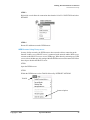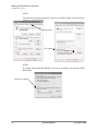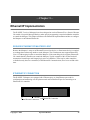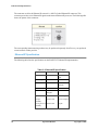
1
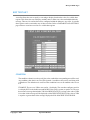
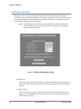
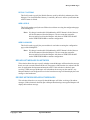
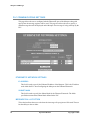
Your Corporate Logo Here
Ethernet/IP Marquee Operation Manual
Model Number: IP-0XXX-T
V1.1
Using The IR Remote . . . . . . . . . . . . . . . . . . . . . . . . . . . . . . . . . . . . . . . . . . . . . . . . . . . . . . . .
Key Usage Of IR Remote . . . . . . . . . . . . . . . . . . . . . . . . . . . . . . . . . . . . . . . . . . . . . . . . . . . . . .
The IR Menus Of The Marquee . . . . . . . . . . . . . . . . . . . . . . . . . . . . . . . . . . . . . . . . . . . . . . . . . .
Programming With The IR Remote . . . . . . . . . . . . . . . . . . . . . . . . . . . . . . . . . . . . . . . . . . . . . . .
Entering Into Program Mode . . . . . . . . . . . . . . . . . . . . . . . . . . . . . . . . . . . . . . . . . . . . . . . . . . . .
Maneuvering Through Setup Menus . . . . . . . . . . . . . . . . . . . . . . . . . . . . . . . . . . . . . . . . . . . . . .
Setting Plant IP Address. . . . . . . . . . . . . . . . . . . . . . . . . . . . . . . . . . . . . . . . . . . . . . . . . . . . . . . .
Setting Plant SubNET Mask . . . . . . . . . . . . . . . . . . . . . . . . . . . . . . . . . . . . . . . . . . . . . . . . . . . .
Setting Plant Default Gateway . . . . . . . . . . . . . . . . . . . . . . . . . . . . . . . . . . . . . . . . . . . . . . . . . . .
Setting Ethernet/IP IP Address. . . . . . . . . . . . . . . . . . . . . . . . . . . . . . . . . . . . . . . . . . . . . . . . . . .
Setting Ethernet/IP Subnet Mask . . . . . . . . . . . . . . . . . . . . . . . . . . . . . . . . . . . . . . . . . . . . . . . . .
Setting Time . . . . . . . . . . . . . . . . . . . . . . . . . . . . . . . . . . . . . . . . . . . . . . . . . . . . . . . . . . . . . . . . .
Setting Date . . . . . . . . . . . . . . . . . . . . . . . . . . . . . . . . . . . . . . . . . . . . . . . . . . . . . . . . . . . . . . . . .
Making The Plant Ethernet Connection . . . . . . . . . . . . . . . . . . . . . . . . . . . . . . . . . . . . . .
Quick Setup . . . . . . . . . . . . . . . . . . . . . . . . . . . . . . . . . . . . . . . . . . . . . . . . . . . . . . . . . . . . . . . . . . . .
Required Equipment. . . . . . . . . . . . . . . . . . . . . . . . . . . . . . . . . . . . . . . . . . . . . . . . . . . . . . . . . . .
Steps To Connect The Marquee Via Ethernet . . . . . . . . . . . . . . . . . . . . . . . . . . . . . . . . . . . . . . .
Detailed Ethernet Setup . . . . . . . . . . . . . . . . . . . . . . . . . . . . . . . . . . . . . . . . . . . . . . . . . . . . . . . . . . .
Configuring the PC . . . . . . . . . . . . . . . . . . . . . . . . . . . . . . . . . . . . . . . . . . . . . . . . . . . . . . . . . . .
Using IPCONFIG To Verify Ethernet Settings . . . . . . . . . . . . . . . . . . . . . . . . . . . . . . . . . . . . . .
Connecting The PC To The Marquee. . . . . . . . . . . . . . . . . . . . . . . . . . . . . . . . . . . . . . . . . . . . . .
Verifying Ethernet Communications . . . . . . . . . . . . . . . . . . . . . . . . . . . . . . . . . . . . . . . . . . . . . .
Connecting To the Marquee’s WEB Server . . . . . . . . . . . . . . . . . . . . . . . . . . . . . . . . . . . . . . . . .
Ethernet/IP Implementation . . . . . . . . . . . . . . . . . . . . . . . . . . . . . . . . . . . . . . . . . . . . . . . . . .
REQUIRE ETHERNET/IP MASTER/CLIENT . . . . . . . . . . . . . . . . . . . . . . . . . . . . . . . . . . . . .
ETHERNET/IP CONNECTION . . . . . . . . . . . . . . . . . . . . . . . . . . . . . . . . . . . . . . . . . . . . . . . . .
Ethernet/IP Specification . . . . . . . . . . . . . . . . . . . . . . . . . . . . . . . . . . . . . . . . . . . . . . . . . . . . . .
INPUT INSTANCE DATA MAP . . . . . . . . . . . . . . . . . . . . . . . . . . . . . . . . . . . . . . . . . . . . . . . .
OUTPUT INSTANCE DATA MAP . . . . . . . . . . . . . . . . . . . . . . . . . . . . . . . . . . . . . . . . . . . . . .
PLC Program Configuration Example . . . . . . . . . . . . . . . . . . . . . . . . . . . . . . . . . . . . . . . . . . . . .
Marquee WEB Pages . . . . . . . . . . . . . . . . . . . . . . . . . . . . . . . . . . . . . . . . . . . . . . . . . . . . . . . . .
MAIN PAGE . . . . . . . . . . . . . . . . . . . . . . . . . . . . . . . . . . . . . . . . . . . . . . . . . . . . . . . . . . . . . . . .
Access Configuration Pages. . . . . . . . . . . . . . . . . . . . . . . . . . . . . . . . . . . . . . . . . . . . . . . . . . . . .
SETUP MENU. . . . . . . . . . . . . . . . . . . . . . . . . . . . . . . . . . . . . . . . . . . . . . . . . . . . . . . . . . . . . . .
BACKUP AND RESTORE PAGE . . . . . . . . . . . . . . . . . . . . . . . . . . . . . . . . . . . . . . . . . . . . . . .
EDIT MESSAGE . . . . . . . . . . . . . . . . . . . . . . . . . . . . . . . . . . . . . . . . . . . . . . . . . . . . . . . . . . . . .
EDIT TEXT LIST . . . . . . . . . . . . . . . . . . . . . . . . . . . . . . . . . . . . . . . . . . . . . . . . . . . . . . . . . . . .
NETWORK SETTINGS . . . . . . . . . . . . . . . . . . . . . . . . . . . . . . . . . . . . . . . . . . . . . . . . . . . . . . .
PLC COMMUNICATIONS SETTINGS . . . . . . . . . . . . . . . . . . . . . . . . . . . . . . . . . . . . . . . . . . .
TIME/DATE SETUP . . . . . . . . . . . . . . . . . . . . . . . . . . . . . . . . . . . . . . . . . . . . . . . . . . . . . . . . . .
VARIABLE COLOR SETTINGS . . . . . . . . . . . . . . . . . . . . . . . . . . . . . . . . . . . . . . . . . . . . . . . .
VARIABLE DATA SETTINGS. . . . . . . . . . . . . . . . . . . . . . . . . . . . . . . . . . . . . . . . . . . . . . . . . .
Mounting Instructions . . . . . . . . . . . . . . . . . . . . . . . . . . . . . . . . . . . . . . . . . . . . . . . . . . . . . . .
Mounting Hardware Included . . . . . . . . . . . . . . . . . . . . . . . . . . . . . . . . . . . . . . . . . . . . . . . . . . .
Copyright © 2008
Operation Manual
5
6
7
8
8
9
10
11
12
13
14
15
16
17
18
18
18
20
20
24
26
28
31
35
35
35
36
37
37
38
41
41
42
43
44
45
49
50
52
54
57
58
61
61
3
Installing Mount Attachment Bolts . . . . . . . . . . . . . . . . . . . . . . . . . . . . . . . . . . . . . . . . . . . . . . .
Mounting Method Examples . . . . . . . . . . . . . . . . . . . . . . . . . . . . . . . . . . . . . . . . . . . . . . . . . . . .
62
63
Specifications . . . . . . . . . . . . . . . . . . . . . . . . . . . . . . . . . . . . . . . . . . . . . . . . . . . . . . . . . . . . . . . .
67
4
Operation Manual
Copyright © 2008
—Chapter 1—
Using The IR Remote
This chapter will discuss the use of the IR remote. The remote is used to initially set the Network
Parameters, Time and Date. It can also be used during operation to allow for resetting of process
variables.
PROG
CPW
PREV
NEXT
MET
TIME
FONT
COL
PAU
SPE
CAP
SYM
GRA
PHR
CLR
BEEP
DEL
ENT
INS
ESC
RUN
Copyright © 2006
A
B
C
D
E
F
G
H
I
J
K
L
M
N
O
P
Q
R
S
T
U
V
W
X
Y
Z
1
2
3
4
5
6
7
8
9
0
ALT
Operation Manual
5
Using The IR Remote
Key Usage Of IR Remote
There are many keys that are not currently used for the operation of the Marquee display. The
following lists the keys that have operation capability with the marquee.
KEY
PROG
USAGE
Enter Program Mode
PREV
Go To Previous Program Screen
NEXT
Go To Next Program Screen
Move Cursor To Left
Move Cursor To Right
RUN
Return to Operating Mode
Y
Used For Conformation Of Change
N
Used for Rejection Of Change
0-9
Numeric Keys For Data Entry
Table 1—IR Remote Key Usage
6
Operation Manual
Copyright © 2006
Using The IR Remote
The IR Menus Of The Marquee
The following are the menus that can be accessed via the IR remote. These menus allow the user to
configure the basic settings of the Marquee display.
Note: On 1 Line units the ENT key must be pressed to access second line of menu.
Menu
Usage
PLANT IP ADDRESS
192.168.1.200
PLANT NET MASK
255.255.255.000
PLANT GATEWAY
000.000.000.000
E/IP IP ADDRESS
192.168.1.200
E/IP SUBNET MASK
255.255.255.000
SET TIME
02:47:37
SET DATE
06/10/06
Allows the user to set the Ethernet
IP address for the built in plant
ethernet port of the Marquee.
Allows the user to set the Ethernet
SUB NET MASK for the built in
plant Ethernet port of the
Marquee.
Allows the user to set the Ethernet
DEFAULT GATEWAY for the
built in plant Ethernet port of the
Marquee. Not present on 1 line
units.
Allows the user to set the Ethernet
IP address for the Ethernet/IP port
of the Marquee.
Allows the user to set the Ethernet
SUBNET Mask for the
Ethernet/IP port of the Marquee.
Allows the user to set the TIME
for the built in real time clock of
the Marquee.
Allows the user to set the DATE
for the built in real time clock of
the Marquee.
Table 2—Marquee Configuration Menus
Copyright © 2006
Operation Manual
7
Using The IR Remote
Programming With The IR Remote
The following section will describe the steps that are taking in order to enter program mode and
accessing the Marquee setup menus. In this section the user will be instructed on how to accomplish
the following tasks.
• Set the Ethernet parameters of the Marquee
• Set the Time and Date on the Marquee display
Entering Into Program Mode
In order to access the setup menus the user must put the Marquee into program mode. This is as
simple as pressing the PROG key on the IR remote.
PROG
CPW
PREV
NEXT
MET
TIME
FONT
COL
The follow message will be displayed on the Marquee.
PLANT IP ADDRESS
192.168.1.200
Note: The user should be within 20 Ft of the Marquee in order for IR operations!
8
Operation Manual
Copyright © 2006
Using The IR Remote
Maneuvering Through Setup Menus
Once in program mode, the user uses the PREV and NEXT keys to scroll through the setup menus.
PROG
CPW
PREV
NEXT
MET
TIME
FONT
COL
PAU
SPE
CAP
SYM
GRA
PHR
CLR
BEEP
DEL
ENT
By using these keys the user can select the menu item that is desired and take appropriate action. The
NEXT key takes the user to the next menu and the PREV key goes back to the previous menu. If
the user is on the last menu and presses the NEXT key the first menu item will be displayed. If the
user is on the first menu item and presses the PREV key the last menu item will be displayed.
PREV
NEXT
PLANT IP ADDRESS
192.168.1.200
E/IP IP ADDRESS
192.168.1.200
PLANT NET MASK
255.255.255.000
E/IP SUBNET MASK
255.255.255.000
PLANT GATEWAY
000.000.000.000
SET TIME
12:10:05
SET DATE
10/10/06
Note: On 1 line units the second line of the menu is accessed by pressing the ENT on the IR
remote.
Copyright © 2006
Operation Manual
9
Using The IR Remote
Setting Plant IP Address
The user can set the Ethernet IP address of the built in Ethernet port via the IR remote. Follow these
steps to accomplish this task.
1. Press the PROG key to put Marquee into program mode.
PROG
CPW
PREV
NEXT
MET
TIME
FONT
COL
PAU
SPE
CAP
SYM
GRA
PHR
CLR
BEEP
DEL
ENT
INS
ESC
RUN
A
B
C
D
E
F
G
H
I
J
K
L
M
N
O
P
Q
R
S
T
U
V
W
X
Y
Z
1
2
3
4
5
6
7
8
9
0
2. The Following message will appear on the Marquee.
PLANT IP ADDRESS
192.168.1.200
3. The user should notice that the first digit within the
IP address is larger than the reset. This indicates the
cursor position.
4. The cursor position can be moved by pressing the
or the
key of the remote. As you move the cursor
the enlarged value will move across the Marquee to
indicate current cursor position.
Example: 192.168.1.200 Press
192.168.1.200 Press
192.168.1.200
5. Pressing any of the numeric keys will change the
value of the current position to that value and move
the cursor position to the right.
ALT
6. Once the proper IP address is displayed press the RUN
key. The confirmation message will be displayed.
ACCEPT NEW IP
PRESS Y FOR YES
7. At this point pressing the Y key will change the
Marquees IP address and return the Marquee to
operating mode.
If the N key is pressed then the IP address will not be
changed and the Marquee will return to operating mode.
10
Operation Manual
Copyright © 2006
Using The IR Remote
Setting Plant SubNET Mask
The user can set the Ethernet SubNet Mask of the built in Ethernet port via the IR remote. Follow
these steps to accomplish this task.
1. Press the PROG key to put Marquee into program mode.
PROG
CPW
PREV
NEXT
MET
TIME
FONT
COL
PAU
SPE
CAP
SYM
GRA
PHR
CLR
BEEP
DEL
ENT
INS
ESC
RUN
A
B
C
D
E
F
G
H
I
J
K
L
M
N
O
P
Q
R
S
T
U
V
W
X
Y
Z
1
2
3
4
5
6
7
8
9
0
ALT
2. The Following message will appear on the Marquee.
PLANT IP ADDRESS
192.168.1.200
3. Press the NEXT key on the remote to go to the
NET MASK menu item. The follow will be displayed.
PLANT NET MASK
255.255.255.000
4. The user should notice that the first digit within the
mask is larger than the rest. This indicates the
cursor position.
5. The cursor position can be moved by pressing the
or the
key of the remote. As you move the cursor
the enlarged value will move across the Marquee to
indicate current cursor position.
Example: 255.255.255.0 Press
255.255.255.0
Press
255.255.255.0
6. Pressing any of the numeric keys will change the
value of the current position to that value and move
the cursor position to the right.
7. Once the proper SubNet Mask is displayed press the RUN
key. The confirmation message will be displayed.
ACCEPT NEW IP
PRESS Y FOR YES
8. At this point pressing the Y key will change the
Marquees Subnet Mask and return the Marquee to
operating mode.
If the N key is pressed then the Subnet Mask will not be
changed and the Marquee will return to operating mode.
Copyright © 2006
Operation Manual
11
Using The IR Remote
Setting Plant Default Gateway
The user can set the Ethernet Default Gateway of the built in Ethernet port via the IR remote. Follow
these steps to accomplish this task.
1. Press the PROG key to put Marquee into program mode.
PROG
CPW
PREV
NEXT
MET
TIME
FONT
COL
PAU
SPE
CAP
SYM
GRA
PHR
CLR
BEEP
DEL
ENT
INS
ESC
RUN
A
B
C
D
E
F
G
H
I
J
K
L
M
N
O
P
Q
R
S
T
U
V
W
X
Y
Z
1
2
3
4
5
6
7
8
9
0
ALT
2. The Following message will appear on the Marquee.
PLANT IP ADDRESS
192.168.1.200
3. Press the NEXT key two times on the remote to go to the
GATEWAY menu item. The follow will be displayed.
PLANT GATEWAY
000.000.000.000
4. The user should notice that the first digit within the
gateway is larger than the rest. This indicates the
cursor position.
5. The cursor position can be moved by pressing the
or the
key of the remote. As you move the cursor
the enlarged value will move across the Marquee to
indicate current cursor position.
Example: 255.255.255.0 Press
255.255.255.0
Press
255.255.255.0
6. Pressing any of the numeric keys will change the
value of the current position to that value and move
the cursor position to the right.
7. Once the proper GATEWAY is displayed press the RUN
key. The confirmation message will be displayed.
ACCEPT NEW IP
PRESS Y FOR YES
8. At this point pressing the Y key will change the
Marquees Gateway and return the Marquee to
operating mode.
If the N key is pressed then the Gateway will not be
changed and the Marquee will return to operating mode.
12
Operation Manual
Copyright © 2006
Using The IR Remote
Setting Ethernet/IP IP Address
The user can set the Ethernet/IP IP Address of the built in Ethernet/IP port via the IR remote. Follow
these steps to accomplish this task.
1. Press the PROG key to put Marquee into program mode.
PROG
CPW
PREV
NEXT
MET
TIME
FONT
COL
PAU
SPE
CAP
SYM
GRA
PHR
CLR
BEEP
DEL
ENT
INS
ESC
RUN
A
B
C
D
E
F
G
H
I
J
K
L
M
N
O
P
Q
R
S
T
U
V
W
X
Y
Z
1
2
3
4
5
6
7
8
9
0
ALT
2. The Following message will appear on the Marquee.
PLANT IP ADDRESS
192.168.1.200
3. Press the NEXT key three times on the remote to go to the
E/IP IP ADDRESS menu item. The follow will be displayed.
E/IP IP ADDRESS
192.168.1.200
4. The user should notice that the first digit within the
E/IP Address larger than the rest. This indicates the
cursor position.
5. The cursor position can be moved by pressing the
or the
key of the remote. As you move the cursor
the enlarged value will move across the Marquee to
indicate current cursor position.
Example: 255.255.255.0 Press
255.255.255.0
Press
255.255.255.0
6. Pressing any of the numeric keys will change the
value of the current position to that value and move
the cursor position to the right.
7. Once the proper IP address is displayed press the RUN
key. The confirmation message will be displayed.
ACCEPT NEW IP
PRESS Y FOR YES
8. At this point pressing the Y key will change the
Marquees Gateway and return the Marquee to
operating mode.
If the N key is pressed then the Gateway will not be
changed and the Marquee will return to operating mode.
Copyright © 2006
Operation Manual
13
Using The IR Remote
Setting Ethernet/IP Subnet Mask
The user can set the Ethernet/IP IP Address of the built in Ethernet/IP port via the IR remote. Follow
these steps to accomplish this task.
1. Press the PROG key to put Marquee into program mode.
2. The Following message will appear on the Marquee.
PROG
CPW
PREV
NEXT
MET
TIME
FONT
COL
PAU
SPE
CAP
SYM
GRA
PHR
CLR
BEEP
DEL
ENT
INS
ESC
RUN
PLANT IP ADDRESS
192.168.1.200
3. Press the NEXT key four times on the remote to go to the
E/IP SUBNET MASK menu item. The follow will be displayed.
E/IP SUBNET MASK
255.255.255.000
A
B
C
D
E
F
G
H
I
J
K
L
M
N
O
P
Q
R
S
T
U
V
W
X
Y
Z
1
2
3
4
5
6
7
8
255.255.255.0
9
0
ALT
255.255.255.0
4. The user should notice that the first digit within the
E/IP Address larger than the rest. This indicates the
cursor position.
5. The cursor position can be moved by pressing the
or the
key of the remote. As you move the cursor
the enlarged value will move across the Marquee to
indicate current cursor position.
Example: 255.255.255.0 Press
Press
6. Pressing any of the numeric keys will change the
value of the current position to that value and move
the cursor position to the right.
7. Once the proper Subnet Mask is displayed press the RUN
key. The confirmation message will be displayed.
ACCEPT NEW IP
PRESS Y FOR YES
8. At this point pressing the Y key will change the
Marquees Gateway and return the Marquee to
operating mode.
If the N key is pressed then the Gateway will not be
changed and the Marquee will return to operating mode.
14
Operation Manual
Copyright © 2006
Using The IR Remote
Setting Time
The user can set the time of the built in real time clock via the IR remote. Follow these steps to
accomplish this task.
1. Press the PROG key to put Marquee into program mode.
PROG
CPW
PREV
NEXT
MET
TIME
FONT
COL
PAU
SPE
CAP
SYM
GRA
PHR
CLR
BEEP
DEL
ENT
INS
ESC
RUN
A
B
C
D
E
F
G
H
I
J
K
L
M
N
O
P
Q
R
S
T
U
V
W
X
Y
Z
1
2
3
4
5
6
7
8
9
0
ALT
2. The Following message will appear on the Marquee.
IP ADDRESS
192.168.1.200
3. Press the NEXT key five times on the remote to go to the
SET TIME menu item. The follow will be displayed.
SET TIME
12:10:05
4. The user should notice that the first digit within the
time is larger than the rest. This indicates the
cursor position.
5. The cursor position can be moved by pressing the
or the
key of the remote. As you move the cursor
the enlarged value will move across the Marquee to
indicate current cursor position.
Example: 12:10:05
2
1 :10:05
Press
Press
12:10:05
6. Pressing any of the numeric keys will change the
value of the current position to that value and move
the cursor position to the right.
7. Once the proper Time is displayed press the RUN
key which set the new time and put the Marquee
into operating mode.
Copyright © 2006
Operation Manual
15
Using The IR Remote
Setting Date
The user can set the date of the built in real time clock via the IR remote. Follow these steps to
accomplish this task.
1. Press the PROG key to put Marquee into program mode.
2. The Following message will appear on the Marquee.
PROG
CPW
PREV
NEXT
MET
TIME
FONT
COL
PAU
SPE
CAP
SYM
GRA
PHR
CLR
BEEP
DEL
ENT
INS
ESC
RUN
A
B
C
D
E
F
G
H
I
J
K
L
M
N
O
P
Q
R
S
T
U
V
W
X
Y
Z
1
2
3
4
5
6
7
8
9
0
IP ADDRESS
192.168.1.200
3. Press the NEXT key six times on the remote to go to the
SET TIME menu item. The follow will be displayed.
SET DATE
10/10/06
4. The user should notice that the first digit within the
date is larger than the rest. This indicates the
cursor position.
5. The cursor position can be moved by pressing the
or the
key of the remote. As you move the cursor
the enlarged value will move across the Marquee to
indicate current cursor position.
Example: 10/10/06
Press
1 0/10/06
Press
ALT
10/10/06
6. Pressing any of the numeric keys will change the
value of the current position to that value and move
the cursor position to the right.
7. Once the proper Time is displayed press the RUN
key which set the new date and put the Marquee
into operating mode.
16
Operation Manual
Copyright © 2006
—Chapter 2—
Making The Plant Ethernet Connection
This chapter describes the steps that are taken in order to connect the Marquee to a Plant ethernet
network or configuration PC to allow the configuration of the Marquee.
The IP-0xxx-T has two ethernet ports. A plant ethernet port, which is accessed through the RJ45
connector on the side of the Marquee, and an Ethernet/IP Ethernet port which is accessed via the EIP
port on the bottom of the Marquee.
Plant Ethernet Connection
Ethernet/IP Connection
The Plant Ethernet port is used for configuration, monitoring and data collection from the Marquee. The
EIP port is used to connect the Marquee to a Ethernet/IP master/client device. The Marquee operates as
an I/O server on the Ethernet/IP network, allowing any client that supports an I/O connection type 1 to
control the message being displayed and the data that may be embedded within that message.
In most cases, the first step in configuring the Marquee is physically connecting the Marquee to what is
known as a configuration PC. A configuration PC can be a laptop or desk-top PC that is equipped with
an ethernet port and has WEB browser software installed. There are many different WEB browsers
available on the market today. Please refer to the documentation for WEB browser that is being used if
it is unclear what is needed to be accomplished.
The Marquee can be connected directly to a PC’s ethernet port or connected to the facility network. It
is recommended that the first time a user connects directly to the Marquee and does not connect to the
facility network. By connecting directly, the user has more control over the ethernet network settings and
the need to consult with the IT department or network administrator of the facility is not required.
Note: Prior to connecting to the facility network, it is highly recommended to consult the facility
IT department or the network administrator of the facility.
Copyright © 2006
Operation Manual
17
Making The Plant Ethernet Connection
Quick Setup
Quick Setup
This section is designed for the user who is familiar with connecting devices via ethernet. This section
assumes a direct connection between the ethernet port of a PC and the Ethernet port of the Marquee.
If the user is not familiar with connecting ethernet devices or configuring ethernet Parameters of the PC
it is highly recommended to go to the section Detailed Ethernet Setup section.
Required Equipment
• DataVisor Marquee
• PC with Ethernet port and a Web browser installed
Note: The user must have administrator rights on the PC
• An Ethernet cross cable or a switch with an Ethernet patch cable.
Steps To Connect The Marquee Via Ethernet
These steps use the factory default ethernet parameters that are set in the Marquee.
• IP Address 192.168.1.200
• Subnet Mask 255.255.255.0
1. Connect a ethernet cross-over cable between the PC and the Marquee
Marquee Ethernet Port
2. Apply power to the Marquee
120 Vac Power Connection
18
Operation Manual
Copyright © 2006
Making The Plant Ethernet Connection
Quick Setup
3. Power the PC
4. Configure the PC’s ethernet port.
• IP address 192.168.1.100
• SubNet Mask 255.255.255.
Note: Refer to the section Set the PC for Fixed IP Address for detailed instructions.
4. Start the WEB browser application and enter the IP address of the Marquee in the address field.
In the address bar type http://192.168.1.200 then preset the ENTER key
http://192.168.1.200
Note: On many browsers the http:// is automatically added to the address so the user
does not need to type it in.
6. At this point the MONITOR page of the Marquee should be displayed in Internet Explorer
7. The user may now access the configuration WEB pages of the Marquee.
Note: Please refer to the section Marquee Configuration Pages for details on the
configuration pages.
If the user has problems accessing the Marquee’s WEB pages, please follow the detailed steps in the
following section.
Copyright © 2006
Operation Manual
19
Making The Plant Ethernet Connection
Detailed Ethernet Setup
Detailed Ethernet Setup
This section describes in detail the steps to establish an ethernet connection to the Marquee in order to
configure it’s operation. This section assumes the user will be using the default ethernet settings of the
Marquee. If the user changes the default ethernet settings, such as the IP address, the user must use the
new settings in place of the defaults when referenced in this section.
• Default IP address of Marquee 192.168.1.200
• Default SubNet Mask of Marquee 255.255.255.0
• Default Gateway of Marquee 0.0.0.0
This section is for connecting the Marquee directly to the PC. If the user wishes to connect the Marquee
to the facility network, it is highly advised that the network administrator or IT department is involved.
This is suggested so as the Ethernet network parameters of the Marquee can be configured to match the
facility network parameters.
Configuring the PC
The first step in making an Ethernet connection to the Marquee is to configure the PC so as the
Ethernet port of the PC can communicate to the Marquee. After the PC has been powered up follow
these steps to verify the configuration of the PC.
Note: Prior to making changes to the ethernet configuration of the PC the existing
configuration should be documented. The user may be required to revert back to the
existing configuration in order to connect to the facility network.
20
Operation Manual
Copyright © 2006
Making The Plant Ethernet Connection
Detailed Ethernet Setup
Set the PC for a Fixed IP Address WINDOWS XP
Many facility networks in use today use what is known as DHCP to allow a server on the
network to assign ethernet parameters to the PCs that are connected to the network. When
connecting directly from the PC to another ethernet device such as the Marquee, the user must
assign the Ethernet parameters of the PC manually.
Step 1
On the PC, click on START followed by CONTROL PANEL.
Note: Depending on the operation system of the PC the user may need to select
SETTINGS in order to access the CONTROL PANEL.
CONTROL
PANEL
START
Step 2
In Control Panel double click on NETWORK CONNECTIONS.
Copyright © 2006
Operation Manual
21
Making The Plant Ethernet Connection
Detailed Ethernet Setup
Step 3
Under NETWORK CONNECTIONS find the Icon that says LOCAL AREA NETWORK.
Then double click on this ICON.This allows the user to configuration the PC’s ethernet port.
Step 4
One of two screens will be displayed. If the screen 1 is displayed, click the PROPERTIES
button and screen 2 will be displayed.
SCREEN TYPE 1
SCREEN TYPE 2
Properties Button
STEP 5
Select selection INTERNET PROTOCOL (TCP/IP) in the THIS CONNECTION USES
THE FOLLOWING ITEMS box. Then click the PROPERTIES button.
SELECT THIS
ENTRY
PROPERTIES
BUTTON
22
Operation Manual
Copyright © 2006
Making The Plant Ethernet Connection
Detailed Ethernet Setup
STEP 6
The properties for the TCP/IP communications is displayed. If the window looks like the
screen below then the PC is set for connecting to as DHCP server. This means that the PC’s
ethernet parameters are generated by a DHCP server on the facility network. In order to
make a direct connection to the Marquee the user must manually enter the Ethernet
parameters. To accomplish this first select the item USE THE FOLLOWING IP
ADDRESS. At this point the user will enter the IP address 192.168.1.100 and the SubNet
Mask of 255.255.255.0.
After entry is completed click the OK button on each of the Network windows. This will
cause the PC to accept the changes and reconfigure the local Ethernet port.
Select
Enter IP address
and Subnet Mask
Click OK
Click OK
Click Close
NOTE: THIS SCREEN MAY
NOT BE DISPLAYED
Copyright © 2006
Operation Manual
23
Making The Plant Ethernet Connection
Detailed Ethernet Setup
Using IPCONFIG To Verify Ethernet Settings
This section is used to verify that the local Ethernet port of the PC is configured properly. In this
section a detail description of the use of the IPCONFIG utility is demonstrated.
STEP1
From the START menu click on the RUN operation.
RUN operation
START
STEP 2
The RUN command entry box will appear. Enter CMD into the open field of this window
then click the OK Button. This will allow the user access to the command line entry prompt
of WINDOWS.
TYPE CMD
24
CLICK OK
Operation Manual
Copyright © 2006
Making The Plant Ethernet Connection
Detailed Ethernet Setup
STEP 3
At this point the command line entry is displayed. At the Command Prompt type
IPCONFIG and then press the ENTER key of the keyboard.
Type IPCONFIG then press the ENTER key
The Ethernet parameters of the PC’s Ethernet port will be displayed. Verify that the IP
address and Subnet mask match the entries previously entered. If the parameters do not
match type:
• Verify that the parameters were entered correctly in the Network Properties window
from the previous procedure.
• Reboot the PC and repeat this procedure.
Note: If the user is unable to successfully set the Ethernet parameters please consult
the facility IT department or network administrator.
Ethernet Parameters for Local Port
Copyright © 2006
Operation Manual
25
Making The Plant Ethernet Connection
Detailed Ethernet Setup
Connecting The PC To The Marquee
Cable Description
This section discussing the steps to connect the Marquee directly to the PC.
There are two types of Ethernet cables available in today’s market.
A patch or straight cable is used when connecting an Ethernet device to a Switch or HUB.
A Cross Over cable is used when connecting one Ethernet Device, such as a PC, to another Ethernet
Device, such as the Marquee, without a HUB or Switch. This is known as a direct connection and
requires that the Ethernet cable crosses the Ethernet signals. A Cross Over cable is included with the
Marquee for this purpose. If the user is connecting the Marquee to a HUB or Switch, the user must
supply the Patch or Straight Through cable.
Figure 1—Ethernet Cable Pinouts
26
Operation Manual
Copyright © 2006
Making The Plant Ethernet Connection
Detailed Ethernet Setup
Connecting the Ethernet Cable
Prior to connecting the Marquee to the PC, both the PC and Marquee should be powered down.
Connect the Cross cable to the Ethernet port of the marquee. The Ethernet port is located on the
right side of the Marquee.
Back of Marquee
Ethernet Port
120 Vac Power Connection
Connect the other end of the Cross cable to the PC’s Ethernet Port.
PC’s Ethernet
Port
Marquee Ethernet Port
Power up both the PC and Marquee. After the PC has booted the user should check that the
LINK light of the PC’s Ethernet port is lit.The LINK light is lit when a physical connection is
made between the PC’s ethernet port and another Ethernet device, such as the Marquee. If the
LINK light is lit then the PC is properly connected to the Marquee.
If the LINK light is not lit check the following:
• Verify the Marquee is powered
• Verify the cable is a cross over cable
• Verify the Ethernet port of the PC is Enabled
Link Light
Copyright © 2006
Transmit Light
Operation Manual
27
Making The Plant Ethernet Connection
Detailed Ethernet Setup
Verifying Ethernet Communications
The previous section verified the physical connection between the Ethernet port of the PC and the
Marquee. This section will be used to verify a communication connection exists between the
Marquee and the PC.
In order to communicate to the Marquee a communication connection must be established. The
physical connection indicates that communication can physically occur but does not verify that the
Ethernet parameters match between the Marquee and the PC. This section is used to verify the
Ethernet Parameters of both the PC and Marquee.
STEP 1
On the PC, click START followed by RUN.
RUN operation
START
28
Operation Manual
Copyright © 2006
Making The Plant Ethernet Connection
Detailed Ethernet Setup
STEP 2
The RUN command entry box will appear. Enter CMD into the open field of this window
then click the OK Button. This will allow the user access to the command line entry prompt
of WINDOWS.
TYPE CMD
CLICK OK
STEP 3
At this point the command line entry is displayed. At the Command Prompt type PING
192.168.1.200 and then press the ENTER key of the keyboard. This operation sends a low
level command to verify that communications can be established. The following screen
shots display the three different responses that may occur during this operation along with
the description of the response.
Reply From
This is an indication that Ethernet communication is established to the Marquee. Proceed
to next section.
Copyright © 2006
Operation Manual
29
Making The Plant Ethernet Connection
Detailed Ethernet Setup
Request timed out
This indicates that the connection to the Marquee could not be established.
• Verify the IP address and Subnet Mask are correct on the Marquee
• Verify cabling and LINK light is lit
• Verify Ethernet settings of PC
Response
Destination Host Unreachable
This is an indication that the PC’s Ethernet settings are not correct. This is a common error
when the IP address or Subnet mask is set incorrectly.
• Verify the PC’s Ethernet settings
• Reboot pc
30
Operation Manual
Copyright © 2006
Making The Plant Ethernet Connection
Detailed Ethernet Setup
Connecting To the Marquee’s WEB Server
In this section a detailed explanation of the steps that are used to access the built in WEB sever of
the Marquee are discussed.
There are many different WEB browser software packages available on the market today. In this
section a general overview of WEB browser settings are discussed. Most WEB browsers support the
settings discussed in this section. The user should reference documentation specific to the WEB
browser that is being used to determine how settings are configured within a given WEB browser.
Note:
In most cases no setting changes are required to the WEB browser. Only in specific
cases is this required.
Step 1
Start the WEB Browser on the PC.
Step 2
In the Address Bar type HTTP://192.168.1.200.
Note: 192.168.1.200 is the default IP address of the Marquee. If this has been
changed by the user, change the IP address to match the IP address of the
Marquee.
http://192.168.1.200
Note: On many browsers the http:// is automatically added to the address so the
user does not need to type it in.
Step 3
At this point one of two items will be displayed in the WEB Browser.
Marquee’s Monitor Screen Appears
This is an indication that the WEB browser has established a connection to the Marquee’s
WEB server. The user can now proceed to configure the Marquee.
Copyright © 2006
Operation Manual
31
Making The Plant Ethernet Connection
Detailed Ethernet Setup
No Monitor Page is Displayed
The Monitor page is not displayed and a message such as WEB PAGE CAN NOT BE
LOADED or FOUND. This error can be caused by the WEB browser’s settings not being
configured properly. The most common reasons for this error are listed below.
Note: It is assumed the user has followed the proceeding sections to verify Ethernet
communication to the Marquee. If not please refer to these sections to verify
that the Ethernet settings of the PC are correct.
WEB browser using wrong Ethernet Connection
In many PCs, such as a laptop, more than one Ethernet connection exists. In many cases a
wireless Ethernet connection exist on the PC and because of this the WEB browser uses this
connection as the default Ethernet Connection.
The solution for this is to DISABLE all Ethernet connections except the LOCAL Ethernet
port.
STEP 1
Click on START followed by Control Panel.
Control Panel
START
STEP 2
Click on NETWORK CONNECTIONS.
32
Operation Manual
Copyright © 2006
Making The Plant Ethernet Connection
Detailed Ethernet Setup
STEP 3
Right click on each Network connection other than the LOACL CONECTION and select
DISABLE.
STEP 4
Restart PC and then restart the WEB browser.
WEB Browser Using Proxy server
In many facility networks, the WEB browser does not make a direct connection to the
Internet. In these cases a PROXY server is connected to the network and the WEB server
connects to this PROXY server to access WEB pages. When directly connecting to a WEB
server, such as the Marquee, this setting within the WEB browser must be turned off. Follow
these steps to disable the PROXY server.
STEP 1
Open the WEB browser.
STEP 2
Within the WEB browser select TOOLS followed by INTERNET OPTIONS
TOOLS
Internet Options
Copyright © 2006
Operation Manual
33
Making The Plant Ethernet Connection
Detailed Ethernet Setup
STEP 3
The following screen will be displayed. Select the CONNECTIONS TAB. Followed by
clicking on LAN SETTINGS.
Connections
LAN settings
STEP 4
IF selected, deselect PROXY SERVER. Click OK on all windows and restart the WEB
BROWSER.
Deselect by clicking
34
Operation Manual
Copyright © 2006
—Chapter 3—
Ethernet/IP Implementation
The IP-0XXX-T series of Marquees have been designed to work on Ethernet/IP as a Generic Ethernet
I/O module. No special Message Blocks or other special programming is required within the controller
to control the Marquee. This chapter will discuss the Ethernet/IP implementation and how to configure
the Marquee on an Ethernet/IP network.
REQUIRE ETHERNET/IP MASTER/CLIENT
Because the Marquee is setup as an Ethernet/IP server/slave device, a client/master device is required
to exchange data and message numbers to the Marquee. The Client/master must support Ethernet/IP
Class 1 I/O Messaging in order to control the Marquee. If the controlling device supports Ethernet/IP
I/O control then the controller can control the Marquee. Typical examples of this are the Rockwell
Automation ControlLogix and CompaqLogix series of controllers. There may be other controllers
available but only these two controllers, with Ethernet/IP Communications, have been verified at this
time.
ETHERNET/IP CONNECTION
The IP-0XXX-T Marquees are equipped with 2 Ethernet ports. A plant Ethernet port used for
configuration and monitoring over the plant network and an Ethernet/IP port for connecting to an
Ethernet/IP I/O controller.
Plant Ethernet Connection
Copyright © 2006
Ethernet/IP Connection
Operation Manual
35
Ethernet/IP Implementation
The connector used for the Ethernet/IP network is a M12 D-Coded Ethernet/IP connector. This
connector passes the 4 wire Ethernet/IP signals to the internal Ethernet/IP processor. The following table
shows the pinout of this connector.
The corresponding interconnecting cordsets may be purchased separately from Exor or your preferred
sensor/network cordset provider.
Ethernet/IP Specification
The following table lists the specifications on the IP-0XXX-T Ethernet/IP implementation.
Table 3—Ethernet/IP Specification
Specification
Data
Vendor ID
119
Exor Vendor ID
code
Product Type
24
HMI
Product Code
1
D a t a Vi so r
Marquee
Revision
1
Product Name
D a t a Vis o r
Marquee
Input Assembly
Instance 101
4 ints of inputs
Output
Assembly
Instance 102
32 ints of output
Configuration Instance 128
Assembly
36
Description
Operation Manual
0 bytes
Copyright © 2006
Ethernet/IP Implementation
INPUT INSTANCE DATA MAP
The 4 integers of the input instance are for future use and have no operation at this time.
OUTPUT INSTANCE DATA MAP
The following table describes the output instance of the Marquee and gives a description on each
attribute of the instance.
Table 4—Output Instance Data Map
Offset
Operation
Description
0
Enable
Enable Marquee Communications must always be a
value of 1
1
Message Register 1
Message number to display or if the marquee is in BIT
MESSAGE CALL-UP then controls messages 1-16.
2
Message Register 2
Message number to display or if the marquee is in BIT
MESSAGE CALL-UP then controls messages 17-32.
3
Message Register 3
Message number to display or if the marquee is in BIT
MESSAGE CALL-UP then controls messages 33-48.
4
Message Register 4
Message number to display or if the marquee is in BIT
MESSAGE CALL-UP then controls messages 49-64.
5
Variable Data Register 0
For embedding data into message as @0
6
Variable Data Register 1
For embedding data into message as @1
7
Variable Data Register 2
For embedding data into message as @2
8
Variable Data Register 3
For embedding data into message as @3
9
Variable Data Register 4
For embedding data into message as @4
10
Variable Data Register 5
For embedding data into message as @5
11
Variable Data Register 6
For embedding data into message as @6
12
Variable Data Register 7
For embedding data into message as @7
13
Variable Data Register 8
For embedding data into message as @8
15
Variable Data Register 9
For embedding data into message as @9
16-31
Future Use
No operation at this time
Copyright © 2006
Operation Manual
37
Ethernet/IP Implementation
PLC Program Configuration Example
The following example uses screen shots from RSLogix programing software. This package is used
to program/configure the Rockwell Automation CompaqLogix and ControlLogix family of
controllers.
• STEP 1
Open the controller programing software and start a new application. The user must complete
the mandatory operation such as adding the controller type and hardware including the
Ethernet/IP interface card.
• STEP2
Under I/O configuration, select the Ethernet/IP interface and right click to ADD A NEW
MODULE. Select GENERIC ETHERNET MODULE.
38
Operation Manual
Copyright © 2006
Ethernet/IP Implementation
• STEP 3
Configure the Marquee parameters. Note the NAME enter will be used by the controller
software as the default TAG names.
MODULE PROPERTIES
The following are the properties that must be set in the software in order for the Marquee to
operate correctly.
Table 5—Module Properties
Field
Copyright © 2006
Value
Name
Any valid name. Will be used as TAG name
Comm Format
Data-Int
IP Address
IP address of Marquee
Input
Instance:101 size: 4
Output
Instance:102 size:32
Configuration
Instance:128 size:0
Operation Manual
39
Ethernet/IP Implementation
• STEP 4
Use the generated TAG names in your program.
Note: The Enable Tag (offset 0) must always have a value of 1 to allow the Marquee to
operate.
Message number Tags (offset 1-4) are used to tell the Marquee what message to display. Each
message that is stored within the Marquee has a corresponding Message number. Example to display
the first message the user moves a value of 1 into one of the 4 message number registers. If more
than one message is being requested, the Marquee will automatically cycle through these messages.
Variable Data Registers (offset 5-14) are used to display data onto the Marquee. These registers can
be embedded into the text of the message by the user. What ever value is placed in the register will
be displayed on the Marquee as specified.
40
Operation Manual
Copyright © 2006
—Chapter 4—
Marquee WEB Pages
This chapter discusses the WEB page configuration menus of the Marquee. The Marquee has a built in
WEB server so as the user may use any WEB browser to open the configuration pages and configure
the Marquee for the application at hand. This chapter is designed to give in depth information about each
configuration page. The next chapter gives the user sample setups that a user can use in order to
accomplish some standard tasks.
MAIN PAGE
The Main page is the initial page that is displayed when the user opens a WEB browser and types
in the IP address of the Marquee. The Main Display Page displays the current message that is being
displayed on the Marquee. The user may also configure data from the PLC to be displayed.
PLC Data
Message Being Displayed
Button To Enter The Configuration Pages
Figure 1—Main Page
Copyright © 2006
Operation Manual
41
Marquee WEB Pages
Access Configuration Pages
Access to the configuration pages is password protected. This feature allows only designated
users the ability of changing the Marquee configuration. To access the configuration pages click
the MARQUEE CONFIGURATION button. A password entry screen will be displayed.
Note: The default user name is admin and the default password is admin. This may be
changed in the NETWORK CONFIGURATION page.
WARNING—If the user name or password are changed please record the new setting and store them
in a safe location for future reference.
User defined user name and password (default admin)
Figure 2—Password Entry Page
42
Operation Manual
Copyright © 2006
Marquee WEB Pages
SETUP MENU
The setup menu allows the user to access the Marquee configuration pages. This page consists of 8
configuration page access buttons and a return button.
Access to Configuration Pages
Exit Setup and Return To Main Page
Figure 3—Setup Menu Page
Note: A common operation within all configuration pages is that the APPLY button must be
clicked prior to leaving the page in order for any changes that have been made to take
affect. If the user leaves the page prior to clicking on the APPLY button any changes
made on that page will be discarded.
Copyright © 2006
Operation Manual
43
Marquee WEB Pages
BACKUP AND RESTORE PAGE
This page allows the user to backup the Marquee configuration onto the PC or restore/load a
previously stored configuration into the Marqee.
LOAD AN EXISTING MARQUEE FILE
BROWSE
This button opens the file explorer so the user may find the file to restore/load into the
Marquee.
RESTORE
After a configuration file has been specified, this button initiates the transfer of the file to
the Marquee.
SAVE CURRENT MARQUEE CONFIGURATION TO A FILE
This button is used to initiate the saving of the configuration of the Marquee to a file on the
PC. Upon pressing this button the user selects SAVE and specifies the location to save the
configuration file. Please note that the file name may be changed to better describe the
configuration being saved.
44
Operation Manual
Copyright © 2006
Marquee WEB Pages
EDIT MESSAGE
This page allows the configuration of messages that will be displayed on the Marquee. The user has
the ability to configure up to 100 messages that can be displayed on the Marquee. The message that
is displayed on the Marquee is determined by the value or bits that are active in the MESSAGE
CALL UP registers over Ethernet/IP.
Figure 4—Edit Message Page
MSG #
This field indicates the message number for the corresponding fields to the right. The message
number is used to associate a value to the message. This number is used within the controller
to display the corresponding message on the Marquee. Message numbers range from 1-100,
which in turn allows the user to program up to 100 messages that can be displayed on the
Marquee.
MSG TEXT
This field allows the user to specify the text of the message. The message text is limited to 80
characters. If a message is larger than can be displayed on the Marquee, the Marquee will
automatically parse the message into multiple parts and display one part at a time until the
message is completely displayed. The time that any giving part is displayed is based on the
selection under MINIMUM DISPLAY TIME.
A group of special identifiers are available to be embedded within the text of the message to do
such things as embed variable data. An identifier always starts with the @ character followed
by a single character to specify the operation. The following table lists the identifiers available
to the user.
Copyright © 2006
Operation Manual
45
Marquee WEB Pages
Identifier
Operation
@T or @t
The time of the Marquees real time clock will be
embedded in the message.
@D or @d
The date of the Marquees real time clock will be
embedded in the message.
@R or @r
Characters following this will be displayed in the color
red.
@G or @g
Characters following this will be displayed in the color
green.
@Y or @y
Characters following this will be displayed in the color
yellow.
@N or @n
Forces the text after this identifier to the next line of the
display. Note that if the message is only displayed on
one line then this indicates the start of the next section
of the message to be displayed on that line. Not valid
on 1 line units.
@0 - @9
Variable data index selected will be displayed within
the message. The manner the data is displayed is based
on the settings within the VARIABLE DATA
SETTINGS PAGE.
Table 1—Special Identifiers
FONT
This field is used to specify the character size of the message. Two choices are available 2” or
4” character height.
Note: Not present on 1 line units.
46
Operation Manual
Copyright © 2006
Marquee WEB Pages
LINE
The LINE field is used to select which line the message will be displayed. Please note selection
of line number 3 and 4 are only available on the 4 line model.
Line
Operation
ALL LINES
The message will clear the display then start on the first
line and wrap to consecutive lines.
LINE 1
The message will only clear line #1 and the text of the
message will be displayed on line #1. All other lines of
the display will be unaffected.
LINE 2
The message will only clear line #2 and the text of the
message will be displayed on line #2. All other lines of
the display will be unaffected.
LINE 3
The message will only clear line #3 and the text of the
message will be displayed on line #3. All other lines of
the display will be unaffected.
LINE 4
The message will only clear line #4 and the text of the
message will be displayed on line #4. All other lines of
the display will be unaffected.
Table 2—Line Selection
Note: Not present on 1 line units.
COLOR
The color field allows the user to specify the color of the message to be displayed. The color of
the message can be either a fixed color or based on the color selected for a variable data register.
By choosing a variable color the message can change colors based on the value or state of the
register within the controller. Please note this is the default color and can be overridden by
placing a color change identifier within the text of the message.
Table 3—Color Selection.
Selection
Operation
RED
Message color will be Red.
GREEN
Message Color will be Green.
YELLOW
Message color will be Yellow.
VD0-VD9
Message color will be based on the color associated
with the variable data register.
FLASH
If this checkbox is checked, the message text will flash. Note that if the color selection is based
on a variable this field is ignored and the message will only flash if the color section for the
variable data has been selected to flash.
Copyright © 2006
Operation Manual
47
Marquee WEB Pages
MINIMUM DISPLAY TIME
Display time is time between the display being updated. An example of this is if the message
sent to the display is to big to display at one time then the display will display one portion of
the message followed by the second portion. The time that the first portion is displayed before
displaying the second portion is the display time. Also if multiple messages are being called up
that use the same line, this is the time between each message being displayed.
48
Operation Manual
Copyright © 2006
Marquee WEB Pages
EDIT TEXT LIST
A text list allows the user to specify a text string to display based on the value of a variable data
register. This allows the user to display machine states or other text values embedded within the
message. There are 10 text lists that can be configured within the Marquee. Any of the 10 variable
data registers can be associated to any of these text lists. Refer to VARIABLE DATA SETTINGS
page on how to associate a text list to a variable data register.
CONDITION
The condition column is used to specify the value at which the corresponding text will be used.
Any condition value that is set to 0 will be ignored. 9 condition values can be used along with
a default text. The default text is used if no other condition is true or all condition value are set
to 0.
EXAMPLE: The user sets VD0 to use text list 1 for display. The user then configures text list
1 to display RUN as the default text and DOWN if the value is greater or equal to 10. The user
then creates a message that includes VD0, MACHINE STATE @0. As long as the value of VD0
is less than 10 the message will be displayed as MACHINE STATE RUN. If the value of VD0
is equal to or greater than 10 the message displayed will be MACHINE STATE DOWN.
Copyright © 2006
Operation Manual
49
Marquee WEB Pages
NETWORK SETTINGS
This page is used to configure the Marquee’s built-in Plant ethernet network. This ethernet
connection is used to connect the Marquee to the facility or plant network. This connection is used
to configure the Marquee and monitor the text and data the Marquee is receiving from the PLC
connected to the Ethernet/IP ethernet network.
Note: If the Marquee is to be connected to the plant network, the IT department or
network administrator of your facility should be consulted prior to assigning
ethernet network parameters.
Figure 5—Ethernet Configuration Page
IPADDRESS
This field is used to specify the IP address of the built-in ethernet port of the Marquee. If
an invalid IP address is entered by the user it will be rejected when the APPLY button is
clicked.
SUBNET MASK
This field is used to specify the SubNet mask used by the built-in ethernet port of the
Marquee. If an invalid SubNet mask is entered by the user it will be rejected when the
APPLY button is clicked.
50
Operation Manual
Copyright © 2006
Marquee WEB Pages
DEFAULT GATEWAY
This field is used to specify the Default Gateway used by the built-in ethernet port of the
Marquee. If an invalid Default Gateway is entered by the user it will be rejected when the
APPLY button is clicked.
WEB USER ID
This field is used to specify the user ID that is used when accessing the configuration pages
of the MARQUEE.
Note: If a change is made to this field and then the APPLY button is clicked, the user
will be disconnected from the Marquee. The user must then restart the
browser and log back into the Marquee with the new WEB USER NAME
and/or WEB PASSWORD to continue configuration.
WEB PASSWORD
This field is used to specify the password that is used when accessing the configuration
pages of the MARQUEE.
Note: If a change is made to this field and then the APPLY button is clicked, the user
will be disconnected from the Marquee. The user must then restart the
browser and log back into the Marquee with the new WEB USER NAME
and/or WEB PASSWORD to continue configuration.
BROADCAST MESSAGE ON NETWORK
This selection allows the user to specify whether or not the Marquee will broadcast the message
that is received across the Ethernet Network. The purpose of this function is to reduce both the
time for application development and network traffic. If this selection is checked, upon
receiving a UDP message the Marquee will rebroadcast the message on the network. Any
Marquee that has been configured to receive the broadcast message will then display the same
message as the broadcaster.
RECIEVE NETWORK BROADCAST MESSAGES
This selection allows the user to specify that the Marquee will allow receiving of broadcast
messages. If this selection is checked, upon a Marquee broadcasting a message the Marquee will
display the broadcast message.
Copyright © 2006
Operation Manual
51
Marquee WEB Pages
PLC COMMUNICATIONS SETTINGS
This page allows the user to configure both the Ethernet/IP port of the Marquee along with
specify how the message registers will be used. This page also allows the user to specify a
default message that will be displayed on the Marquee if no message is being called up by the
PLC.
ETHERNET/IP NETWORK SETTINGS
IP ADDRESS
This field is used to specify the Ethernet/IP address of the Marquee. This is the IP address
used within the PLC when configuring the Marquee on the Ethernet/IP network.
SUBNET MASK
This field is used to specify the Subnet Mask for the Ethernet/IP network. The Mask
specified must match the Subnet Mask defined in the PLC.
MESSAGE CALL-UP OPTION
This selection allows the user to select how the 4 message call-up registers will be used. The user
has the ability to choose either:
52
Operation Manual
Copyright © 2006
Marquee WEB Pages
REGISTER VALUE MESSAGE CALL-UP
Each of the 4 message call-up registers are read as a value that corresponds to the message
number. In the register value is greater than 0 then the message number specified will be
displayed on the Marquee.
In this manner, the user only needs to move the value of the message to display into a
message register and the message will be displayed.
BIT LEVEL MESSAGE CALL-UP
This selection is used to specify that the message registers will be examined as a 64 bit array
of bits. In this mode each bit of the message registers controls the display of a single
message number.
Message Register 0 = Messages 1-16
Message Register 1 = Messages 17-32
Message Register 2 = Message 33-48
Message Register 3 = Messages 49-64
In this manner, the user only needs to turn on a bit within a message register and the
corresponding message will be displayed.
DEFAULT MESSAGES
Default messages are the messages that are displayed on the Marquee if the message registers
are a value of 0 or no bits are turned on within the message registers. Due to the fact that a
message can be configured to only write to 1 line of the display, each line has it’s own default
message.
LINE #
Indicates the line that this default message will be displayed on.
MESSAGE TEXT
The text and any special operators for the default message.
COLOR
The color of the text for the message.
FLASHING
Selection to indicate that this message will flash on and off on the Marquee.
MINIMUM DISPLAY TIME
If the message is to large to be displayed at one time, this is the time between the message
being cycled through on the display.
Copyright © 2006
Operation Manual
53
Marquee WEB Pages
TIME/DATE SETUP
The TIME/DATE SETUP page is used to configure the real time clock operations of the
Marquee.
TIME and DATE
These field are used to set the real time clock of the Marquee. The user must supply the time in
24 hour format and the date in month/day/year format. If the user does not supply the correct
format the setting will be ignored. After the user has entered the correct time and date, pressing
the SET TIME/DATE button will initiate the time update to the Marquee.
TIME AND DATE DISPLAY FORMAT
This section allows the user to specify how time and date will be displayed on the Marquee.
TIME
Selection for how time will be displayed if included within a message.
Table 4—TIme Display Format
SELECTION
24 HOUR HH:MM
54
DISPLAYED
Displays time in 24 hour format
including hour and minute only
Operation Manual
Copyright © 2006
Marquee WEB Pages
Table 4—TIme Display Format
SELECTION
DISPLAYED
24 HOUR HH:MM:SS
Displays time in 24 hour format
including hour, minute and seconds.
12 HOUR HH:MM AM/PM
Displays time in 12 hour format
AM/PM with hour and minute only.
12 HOUR HH:MM:SS AM/PM
Displays time in 12 hour format
AM/PM including hour, minute and
second.
DATE
Selection for how the date will be displayed if included within a message.
Table 5—Date Display Format
SELECTION
DISPLAYED
EXAMPLE
DD MMM YYYY
Displays day of month, 3 character 25 Dec 2005
month abbreviation and 4 digit year.
MMM DD YYYY
D i sp l a y s 3 ch a r a c t er m o n t h Dec 25 2005
abbreviation, day of month and 4
digit year.
DD/MM/YYYY
Displays day of month/month/4 25/12/2005
digit year.
MM/DD/YYYY
Displays month/day of month/4 12/25/2007
digit year.
YYYY.MM.DD
Displays 4 digit year.month.day of 2005.12.25
month.
ALLOW NETWORK TIME SYNC.
This option allows the Marquee’s real time clock to be synchronized to a master clock on the
network. In order for this to operate, a marquee on the same network must be defined as a master
clock. The master clock Marquee broadcasts a time sync message that any Marquee that is
configured to ALLOW NETWORK TIME SYNC. received the sync message and updates it’s
real time clock.
Copyright © 2006
Operation Manual
55
Marquee WEB Pages
USE AS MASTER CLOCK
This option is used to specify that this Marquee is the master clock on the network. In turn the
Marquee will broadcast the current time and date to all other Marquees that are defined to
receive the network time sync.
BROADCAST TIME EVERY
If the Marquee is defined as the master clock, this selection allows the user to specify how often
to transmit the time and date onto the network.
56
Operation Manual
Copyright © 2006
Marquee WEB Pages
VARIABLE COLOR SETTINGS
This configuration page is used for configuring the use of variable color changes for the Marquee.
Variable color is configured based on the value of a given variable data register. Each of the ten
variable data registers can be configured so as the value changes the color that the variable is
displayed in. Also the text of a message can change color based on this value. Please refer to EDIT
MESSAGES page for details on how to configure the message to change colors based on a variable.
VALUE
This column allows the user to specify the values that will dictate a color change. The
DEFAULT COLOR is used if the value of the variable data register is 0 or no setpoints have
been configured.
COLOR
The color column allows the user to specify the color to use for the corresponding variable.
The default color is the color of the data if the variable data has a value of 0 or if no other
values are configured. Each of the other color selection rows correspond to the value
column of the same row.
Example: The user wishes to have the color that VD0 is displayed in change based on the
value of VD0. If the value is less than 100 the color will be green. If the value is greater than
or equal to 100 the value will be red. The user sets the default color for VD0 to be green then
sets the first value row to a value of 100 followed by setting the color to be red.
Copyright © 2006
Operation Manual
57
Marquee WEB Pages
VARIABLE DATA SETTINGS
This page is used to configure how the values within the variable data registers will be displayed.
MAIN PAGE TITLE
This field allows the user to specify the text for the title on the MAIN PAGE of the Marquee.
MAIN PAGE REFRESH RATE
This selection allows the suer to specify how often the MAIN PAGE will be automatically
refreshed on the WEB browser.
VARIABLE DATA CONFIGURATION
This section of the page is used to configure how each variable data registers value will be used
and/or displayed.
DATA
This column contains the index of each of the corresponding variable data registers. The
row data to the right is the configuration for the given variable data register.
58
Operation Manual
Copyright © 2006
Marquee WEB Pages
DATA DESCRIPTION
This field allows the user to type in the text that will be displayed on the MAIN PAGE for
corresponding variable data register. Please note that the user must also select MONITOR
DISPLAY in order for the text and value to be displayed on the MAIN PAGE.
# DIGITS
This selection allows the user to specify the number of digits to display for the variable. This
is useful when creating a message with embedded variable data. The # DIGITS specified
will be used by the Marquee to determine the number of characters positions to set aside for
variable data within the message.
PRECISION
This selection allows the user to specify if any of the digits should be placed behind a
decimal point.
Example: Value of variable data 1234
Table 6—Precision
Precision
Selected
Data Displayed
0
1234
1
123.4
2
12.34
3
1.234
4
0.1234
5
.01234
FORMAT
The format selection is used to determine justification, display type or if the value relates
to a text entry within a text list.
Table 7—Variable Data Formats
Format
Copyright © 2006
Description
Leading Spaces
The value of the variable data is displayed
with a length specified under # DIGITS with
and leading 0’s being replaced with spaces.
Leading Zeros
The value of the variable data is displayed
with a length specified under # DIGITS with
and leading 0’s being displayed.
Operation Manual
59
Marquee WEB Pages
Table 7—Variable Data Formats
Format
Description
Time ##:##
Value of variable data register is displayed
with 2 digits followed by a : then the second 2
digits.
Time #:##:##
Value of variable data register is displayed
with 1st digit the a : followed by the next 2
digits followed by a : then the last 2 digits.
TEXT LIST 1-10
The variable data value is used to index within
a text list were the data displayed is a text
string and not the value of the data.
COLOR
The color selection is used to specify the display color of the variable data. The display color
can be a fixed color or can be configured to be a variable color based on the VARIABLE
COLOR configuration.
MONITOR DISPLAY
This selection is used to indicate the user wishes to have the ability of monitor the value of
the variable data on the MAIN PAGE. If selected an entry on the MAIN PAGE will display
the DATA DESCRIPTION along with the value of the variable data.
60
Operation Manual
Copyright © 2006
—Chapter 5—
Mounting Instructions
This chapter will discuss the mounting possibilities available. Mounting hardware is included with each
Marquee.
Mounting Hardware Included
Mount Attachment
Nut 5/16 Qty 4
Slide-In Mount Attachment
Bolt 5/16 (custom) Qty 4
Hanger/Stand Mounting Bracket Qty 2
Mount Interconnect
Nut 6mm Qty 4
Mount Interconnect
Bolt 6mm Qty 4
Swivel Mount Bracket
Copyright © 2006
Operation Manual
61
Mounting Instructions
Installing Mount Attachment Bolts
Prior to mounting the Marquee the mount attachment bolts must be installed.
WARNING—In order to install the mount attachment bolts the end cap on the left (when looking at front
of Marquee) must be removed.
WARNING—DO NOT REMOVE THE END CAP ON THE RIGHT HAND SIDE!
3. Slide 2 to 4 mount bolts into 5. Place 4 END CAP screws.
1. Remove 4 screws holding left
grove. (C)
END CAP. (A)
2. Remove END CAP.(B)
4. Replace END CAP.
C
A
B
Figure 1—Installing Mount Bolts
Note: The number of bolts will be determined by desired mounting method.
Note: Bolts may be installed in top slot or bottom depending on desired mounting method.
62
Operation Manual
Copyright © 2006
Mounting Instructions
Mounting Method Examples
This section illustrates a few of the methods of mounting the Marquee. By no means are these the
only ways to mount the Marquee but are examples of how some customers have mounted the
Marquee.
Chain Mount
Marquee mounting components needed:
• 4 mount attachment bolts
• 4 mount attachment nuts
• 2 hanger mounts
Chain
Mount Attachment Nuts
Mount Attachment Bolts
Top Of Marquee
Chain
Hanger Mounts
Figure 2—Chain Mount Example
Copyright © 2006
Operation Manual
63
Mounting Instructions
Wall Mount With Swivel
Marquee mounting components needed:
• 4 mount attachment bolts
• 4 mount attachment nuts
• 2 hanger mounts
• 2 swivel mounts
• 4 mount interconnect bolts
• 4 mount interconnect nuts
Mount Attachment Nuts
Swivel Mounts
Mount Attachment
Bolts
Hanger Mount
Mount Interconnect Bolts and Nuts
Hanger Mount
Figure 3—Wall Mount
64
Operation Manual
Copyright © 2006
Mounting Instructions
Bottom Mount (8020 Front Mount)
Marquee mounting components needed:
• 4 mount attachment bolts
• 4 mount attachment nuts
• 2 hanger mounts
Mount Attachment Nuts
Bottom of Marquee
Hanger Mounts
MAREQUEE
8020
When Bolting to 8020 please bolt through hole of mounting bracket
Figure 4—Bottom Mount
Copyright © 2006
Operation Manual
65
Mounting Instructions
Bottom Mount (8020 top mount)
Marquee mounting components needed:
• 4 mount attachment bolts
• 4 mount attachment nuts
• 2 Swivel Mounts
Top of Marquee
Mount Attachment Bolts
Mount Attachment Nuts
User Supplied Bolts for 8020
Figure 5—Bottom Mount
66
Operation Manual
Copyright © 2006
—Chapter 6—
Specifications
Table 1—Specifications All Models
LED PITCH
LED COLORS
LED Life
Viewing Angle
Environment
5mm
RED,GREEN
& AMBER
100,000 Hours
160 Deg.
Temp. 0-55 C
Humdity 15-95%
Table 2—Model Specific
Model
Dimensions
Weight
Voltage
Current (max)
IP-0113-T
26”x4.5”x1.75”
2.8 #
24 VDC
2.0 Amps
IP-0213-T
25.5”x6.25”x3.75”
10.8 #
120 VAC
0.8 Amps
IP-0220-T
39.75”x6.25”x3.75” 17.9 #
120 VAC
1.0 Amps
IP-0420-T
39.75”x11”x3.75”
120 VAC
2.0 Amps
Copyright © 2006
26.2 #
Operation Manual
67
Specifications
68
Operation Manual
Copyright © 2006