1
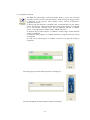
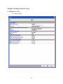
GANG Programmer for flash micro computers
User’s Manual
TESSERA Technology INC.
First Edition December 2012
-1-
Table of Contents
Chapter 1 Summary······································································································3
1.1 System Configuration·····························································································4
Chapter 2 Installation····································································································5
2.1 System Requirement ······························································································5
2.2 Software Installation ······························································································5
2.3 Driver Installation ·································································································6
Chapter 3 Hardware Specifications ···················································································7
3.1 Name of each part ·································································································7
3.2 StickWriter Setting ······························································································ 12
3.3 Basic Specifications ····························································································· 13
Chapter 4 Stick GANG Writer Operation using GUI Software··············································· 14
4.1 Launching GUI Software ······················································································ 14
4.2 Tool Bar············································································································ 16
4.3 Setup Information ······························································································· 17
4.4 HEX File Information ·························································································· 17
4.5 Status ··············································································································· 18
4.6 StickWriter········································································································ 18
4.7 Menu Bar·········································································································· 19
4.7.1 [File] Menu ·································································································· 19
4.7.2 [Programmer] Menu······················································································· 30
4.7.3 [Device] Menu······························································································· 34
4.7.4 [Help] Menu ································································································· 48
Chapter 5 Settings by Device Series················································································· 49
5.1 78K0S/Kx1+ Series ······························································································ 49
5.1.1 Setup Screen ······························································································ 49
5.2 78K0 Series········································································································ 51
5.2.1 Setup Screen ······························································································ 51
5.3 78K0R Series ····································································································· 54
5.3.1 Setup Screen ······························································································ 54
5.4 V850E, V850ES Series ·························································································· 57
5.4.1 Setup Screen ······························································································ 57
5.5 RL78 Series ······································································································· 60
5.5.1 Setup Screen ······························································································ 60
Chapter 6 Others ········································································································ 63
6.1 About each file···································································································· 63
6.2 Using StickWriter by removing it from Stick GANG Writer··········································· 63
6.3 List of Error codes displayed on LCD······································································· 64
-2-
Chapter 1 Summary
Stick GANG Writer is a GANG type flash writer used to simultaneously write program data into up to 8
micro-computers with built-in flash memory.
Since the 32-MByte flash memory is built into the body, it allows up to 8 HEX files and setting files for
each device to be saved. Therefore, “stand-alone operation” is possible, without requiring a PC when
writing.
-
Allows writing with “stand-alone operation”
-
Can simultaneously write on 8 devices using just 1 button
-
Can also start writing 1 device at a time
-
Allows up to 8 HEX files and setting files to be saved into the body
-
Switching between HEX files and setting files is possible without requiring a PC
-
Displays write only files and writing status with LCD
-
Displays the total number of writing devices on LCD
-
Notifies writing results with a buzzer that can be switched ON/OFF
-
Equipped with a function for adding a serial number to each device
-
Easily connected to PC using a USB interface
-
Adaptable to various devices by exchanging the socket board (SGA board) prepared by each
writing device type
-3-
1.1 System Configuration
Windows Personal Computer (Windows XP, Windows7)
USB Cable
SGR-xxxxx*1-yy*28
AC Adapter
SGR-xxxxx*1-yy*24
*1: Varies by target device.
*2: Package geometry of the target device will be included.
SGA board is exchangeable.
-4-
Chapter 2 Installation
2.1 System Requirement
OS
Monitor
Interface
Windows XP (32bit) or Windows 7 (32 / 64bit)
XGA (1024×768 or higher)
USB (Rev1.1/2.0) port
2.2 Software Installation
After inserting the StickWriter Installation CD into the CD drive, the installer launches
automatically.
If the installer is not launched, double-click "Installer.vbs". It detects the OS and run the
"x64¥StickWriterInstaller.msi" for 64bit OS and "x86¥StickWriterInstaller.msi" for 32bit
OS.
For Windows XP, Microsoft .NET Framework 2.0 or later must be pre-installed. If the OS
is Windows XP, the Microsoft .NET Framework 2.0 installer launches.
-5-
2.3 Driver Installation
When Stick GANG Writer is first connected to PC, the appropriate USB driver will be
installed. Launch the GUI after the installation completion message is appeared at the
right-bottom area of Windows screen.
-6-
Chapter 3 Hardware Specifications
3.1 Name of each part
ALL Success LED
GO Switch
LCD
Start Switch
Fail LED
MODE Switch
IC Socket
BUSY LED
FG
SELECT
Switch
Front
USB
Connector
Side
-7-
DC Input
Power
Switch
(1) Start Switch
Writing (EPV Command) will start simultaneously for all connected sockets. The Start switch can
be pressed only when it is lit.
Start
Switch
Socket
1
Socket
2
Socket
3
Socket
4
Socket
5
Socket
6
Socket
7
Socket
8
(2) GO Switch
When the “GO switch” on the SGA board is pressed, writing (EVP command) will start for each
socket. This operates only in “stand-alone” mode when GUI is not launched. Moreover, when an
error occurs during writing, the GO switch cannot be pressed until the ongoing writing in the
device is finished.
GO
GO
GO
GO
GO
GO
GO
GO
Socket
1
Socket
2
Socket
3
Socket
4
Socket
5
Socket
6
Socket
7
Socket
8
(3) BUSY LED
This is the green LED attached under each socket. It will light up when power is supplied to the
socket. Attach or remove the writing device to the socket after confirming that this LED is turned
off.
BUSY LED
-8-
(4) ALL Success LED
The blue light turns on when the following conditions are met.
Also, a buzzer sounds when the LED light turns on. (The buzzer can be turned “OFF” with the
MODE switch.)
-
When all devices have finished successfully as a result of executing the EVP command from
GUI.
When all devices have finished successfully as a result of writing with the Start switch.
When writing was executed into each socket with the GO switch and all writing has finished
successfully. However, when writing on a new device starts before all the devices finish
writing, the light will not turn on.
(5) Fail LED
The red light turns on when the following conditions are met.
Also, a buzzer sounds when the LED light turns on. (The buzzer can be turned “OFF” with the
MODE switch.)
-
When at least one error has occurred, as result of executing the EVP command from GUI.
When at least one error has occurred, as result of writing with the Start switch
When writing was executed into each socket with the GO switch and at least one error has
occurred.
(6) IC Socket
These are sockets to attach to the devices to be written. From the left, they are numbered 1, 2 …8.
Attach them keeping in mind the 1 pin position (▲ mark).
(1)
(2)
(3)
(4)
-9-
(5)
(6)
(7)
(8)
(7) LCD
Various information is displayed.
When launched
After checking the setting file and the HEX file, the following will be displayed.
1:Setting File
PROGRAM:0000
1st line: The specified number of the SELECT switch and the name of the setting file are
displayed.
2nd line: The value of device Checksum of the written HEX file is displayed.
When writing (EPV)
The progress status of each socket is displayed.
st
1:Setting File
1 2 3 4 5
6
7
8
1 line: The specified number of the SELECT switch and the name of the setting file are
displayed.
2nd line: Each socket number as well as the progress status on the right is displayed in a graph.
If the device is unpopulated in the socket or if an error occurs, “X” is displayed.
When the writing finishes successfully in all sockets
The number of written (EVP) devices after activating the power of Stick GANG Writer is
displayed.
1:Setting File
OK:000008 NG:000
1st line: The specified number of the SELECT switch and the name of the setting file are
displayed.
2nd line: The number of devices that were successfully written is displayed to the right of “OK”.
The number of devices in which an error occurred when writing is displayed to
the right of “NG”.
When a writing error has occurred
The progress status of each socket is displayed.
1,2,3,4,5,6,7,8
20
1st line: Socket numbers 1 to 8 are displayed.
2nd line: The error number is displayed under the socket number in which the error occurred.
The example above shows that an error (20) occurred in socket 3.
Refer to the list of error codes at the end for the meaning of this error.
- 10 -
(8) MODE switch
ON/OFF of the buzzer can be set.
1
2
3
4
ALL Success buzzer
ON: The buzzer sounds when the ALL Success LED light turns on (Default
setting)
OFF: The buzzer does not sound even if the ALL Success LED light turns on.
Fail buzzer
ON: The buzzer sounds when the Fail LED light turns on (Default setting)
OFF: The buzzer does not sound even if the Fail LED light turns on.
SYSTEM
Use this when the buzzer is OFF.
Unused
Not used.
(9) SELECT Switch
This is the SELECT Switch of the setting files.
It can be set within 0 to F, but use it within the range of 1 to 8.
When making a change, switch the power to OFF, as changes cannot be made after activating
the power.
In the left example, as the arrow
is at the “4”
position, the SELECT Switch is set at “4”.
(10) USB Connecter
A USB cable for connecting to a PC is connected.
Use the USB cable included for product attachments.
(11) DC Input
Connect the attached AC adapter.
(12) Power Switch
The power of Stick GANG Writer can be switched ON/OFF.
(13) FG
This is Frame GND. Connect by separately preparing an earth cable.
- 11 -
3.2 StickWriter Setting
Output switch
Status LED
Power Switch
Output Switch
This switch is used to specify the voltage when supplying power from the StickWriter, but when
using this with Stick GANG Writer, the voltage can be set to either level. (The switch is set at 5V
when shipped.)
Stick GANG Writer will supply the appropriate voltage to the socket.
Power Switch
This specifies the power supply source to the StickWriter.
Always set the Power Switch to the “U” side, as power is supplied from the USB
connector. (Setting at the time of shipment)
Status LED
The status is displayed with LED under the Power switch.
The light turns on when power from the StickWriter is supplied. In
P
Blue addition, the light flashes when communication to Stick GANG
Power
Writer as well as to the target device is being performed.
F
The light turns on in cases such as when communication with the
Red
Fail
target device fails.
S
The light turns on when the command to the target device succeeds.
Blue
Success
- 12 -
3.3 Basic Specifications
Built-in data memory
Supported communication method
Available voltage supply
PC Interface
Power Supply
Body size
Usage environment conditions
32 Mbyte (NAND Flash: with ECC processing)
UART, clock synchronizer SIO (with/without H/S)
Fixed with SGA board
5V / 3.3V
(For devices that require a voltage other than that
mentioned above, it is to be generated with the SGA
board)
USB 2.0/1.1
AC adapter
Input: AC100 to 240V, 50/60Hz
Output: DC12V, 3.3A
W400 × D230.5 × H55 (mm)
(The height will vary depending on the SGA board)
Temperature: 0ºC to 40ºC
- 13 -
Chapter 4 Stick GANG Writer Operation using GUI Software
4.1 Launching GUI Software
(1) System Connection
Connect Stick GANG Writer to the PC in which the Stick GANG Writer GUI program was
installed with a USB cable.
(2) Launching the GUI Software
Select [Program (P)]->[StickWriter]->[Stick GANG Writer Ver.2] from the Windows Start menu.
Initialize the GUI software by initiating communication with the Stick GANG Writer firmware. If
the initialization process was successful, the window shown in below will be displayed.
- 14 -
(1)
(2)
(4)
(3)
(4)
(5)
(6)
(7)
(8)
(9)
(10)
(3) Configuration of the Windows Screen
(1) Menu Bar (Displayed on top)
(2) Tool Bar (Displayed under the menu)
(3) Setup Information section
(4) HEX File Information section
(5) Status Display section
(6) Progress Status Display section
(7) Trace Display section
(8) StickWriter Status Display section
(9) Checksum, Serial No Display section
(10) Progress status Display section
- 15 -
4.2 Tool Bar
The Tool Bar consists of functions that are commonly used in Device menu.
"Setup" button
"Blank Check" button
"Erase" button
"Program" button
"Verify" button
"Security" button
"Checksum" button
"EPV" button
- 16 -
4.3 Setup Information
The Setup Information section displays key information on the setting file selected and the number of
this setting file.
When GUI is launched, the setting file specified by the SELECT switch on the body of Stick GANG
Writer is selected and becomes the default setting file.
The default setting file can be changed depending on the “setup”, but when GUI finishes, it goes back
to the number specified by the SELECT switch on the body of Stick GANG Writer.
4.4 HEX File Information
This displays HEX File information.
The value of “Checksum (CRC)” is calculated by the file size of the HEX file. Checksum values
similar to “PG-FP4” by Renesas Electronics can be confirmed by “Checksum display” in the “File”
menu.
- 17 -
4.5 Status
This displays information such as execution status of the command and results.
When “Trace display” is checked, information such as execution time of the command will be
displayed in the trace display area.
4.6 StickWriter
This displays the status of the StickWriter.
In the “SGR-xxxxx-yy4” package, there are 4 connections for StickWriter, so the StickWriter display will
also show 4 connections.
“Checksum, Serial No Display section” displays the checksum value when the “Checksum” command in
the “Device” menu is executed. When “EPV with serial No” is executed, the serial No. is displayed.
The Progress Status Display section will show the progress status in numerical values during the
execution of the command, and when the command finishes, the result (“OK” or “NG”) is displayed.
Checksum,
Serial No Display section
Progress Status Display section
- 18 -
4.7 Menu Bar
Depending on the status and type of the actual device, some menus may not be applicable.
4.7.1 [File] Menu
Clicking the [File] menu will display a pull-down menu.
The menu consists mainly of commands for file operations.
(1) [HEX File Download] Menu
StickWriter can download up to 2 HEX files on the built-in memory. Select a
download number and select the HEX file to be written.
- 19 -
Also, you can download a HEX file by clicking one of the "Download" button in
HEX File information section.
Download to HEX File 1
Download to HEX File 2
- 20 -
(2) [HEX File Upload]Menu
Upload and save the HEX file in PC that the file was downloaded on the Stick
GANG Writer. Select a HEX file number, and then enter the HEX file name to be
saved.
(3) [HEX File Delete]Menu
You can delete a HEX file that is downloaded on Stick GANG Writer. Select a
HEX file number to delete.
- 21 -
(4) [Checksum]Menu
The Checksum value of the HEX file downloaded to Stick GANG Writer’s flash memory is
displayed.
Device Checksum: Value calculated using the same algorithm as the target device.
FP4 Algorithm: Value calculated using the same algorithm as Renesas Electronics
programmer “PG-FP4”.
CRC sum (32 bit: 1 M): Value when Program Area of PG-FP4 is set at 1 MByte.
CRC sum (32 bit: 2 M): Value when Program Area of PG-FP4 is set at 2 MByte.
- 22 -
(5) [Parameter File Download] Menu
Select a parameter file to enable downloading to the Stick GANG Writer’s flash memory.
Select a parameter file to download.
Press [OK] to display the update confirmation window.
- 23 -
For registration update
For new registration
The selected parameter file will be downloaded to the flash memory in Stick GANG Writer.
The latest parameter files can be downloaded from our website (http://www.tessera.co.jp).
- 24 -
(6) [Setting File Download] Menu
Select a setting file for download to the Stick GANG Writer’s flash memory.
Select a number to download and press [OK].
- 25 -
Confirm the destination of the download and press [OK] to start downloading.
If the specified location is the default setting (in the case of overwriting), the warning window
shown in below will be displayed and the download will not start.
The downloaded setting file will become the default setting file. (This will be reflected in the
Setup information.)
- 26 -
(7) [Setting File Upload] Menu
Upload the setting file from Stick GANG Writer to a specified location in the host machine.
Select a number to upload and press [OK].
Enter a file name and click "Save" to start uploading.
The saved file can be downloaded from the "Setting File Download" menu.
- 27 -
(8) [Setting File Delete] Menu
Delete a setting file from a specified location in Stick GANG Writer.
Select a number to delete and press [OK].
A confirmation window for the selected location will be displayed. Press [OK] to delete the
setting file.
Keep in mind that when a setting file is deleted, the HEX file corresponding to this setting
file will also be deleted.
- 28 -
(9) [Application Exit] Menu
Exit the Stick GANG Writer GUI software. The user may also exit by clicking the X
button on the right side of the task bar.
You can exit the software without displaying the confirmation message by
changing the "Option" settings in Programmer menu.
Press [OK] to exit the application. Press [Cancel] to cancel the exit.
- 29 -
4.7.2 [Programmer] Menu
Clicking on the [Programmer] menu displays a pull-down menu as shown below. The menu
consists of a set of setup commands related to programming.
(1) [Option] Menu
You can select to display or not to display the confirmation message when
closing the StickWriter GUI software. The setting will be saved to the PC.
(2) [Secure mode] Menu
Stick GANG Writer can be set to Secure Mode.
When Stick GANG Writer is set to Secure Mode, following operations will be
restricted.
• To download, upload, delete any HEX files.
• To download, upload, delete setting files
• To edit setting files (Setup button)
• To download parameter files.
• To use "Checksum" in "File" menu.
• To use "Update Firmware" in "Programmer" menu.
• To use "Read" in "Device" menu.
Enter a password to disable the Secure Mode (max 32 characters).
Because the settings and password are stored in Stick GANG Writer, you can
use the same password even you use other PC to connect to the Stick GANG
Writer.
- 30 -
When it sets to Secure Mode, the title bar displays "(Secure Mode)" as shown in
the figure.
To cancel Secure Mode, select "Secure mode" menu again.
You can cancel Secure Mode by entering the password that you set when you
enabled the Secure Mode.
If you forgot the password, you can click "Delete" button to delete all HEX files
and default setting files for canceling the password.
- 31 -
(3) [Update SW Firmware]Menu
Update all the firmware programs for all the connected StickWriters.
Input the file name and press [Open] to start downloading the firmware.
After the firmware program is successfully downloaded, the window shown in above will be
displayed. Press [OK] to initialize Stick GANG Writer which will complete the process.
- 32 -
(4) [Update GANG Firmware] Menu
Update the firmware program for Stick GANG Writer.
Input the file name and press [Open] to start downloading the firmware
After the firmware program is successfully downloaded, the window shown in above will be
displayed. Press [OK] to initialize Stick GANG Writer which will complete the process.
- 33 -
4.7.3 [Device] Menu
Clicking the [Device] menu displays a pull-down menu. The menu consists mainly of commands
related to programming of the target device, such as deleting, programming and verifying.
- 34 -
(1) [Blank Check] Command
Performs a blank check for the target device connected to Stick GANG Writer. If
the flash memory in the target device has been erased, the blank check will finish
successfully. If the flash memory has not been erased, an error message will be
displayed.
The status displayed when [Blank Check] finishes successfully.
The window displayed if data has been written to all target devices.
- 35 -
(2) [Erase] Command
Erases the flash memory of the target device connected to Stick GANG Writer. If
“Blank check before Erase” is checked in the “Command options” of the [Setup]
window, a blank check is performed before erasing. If the flash memory is blank,
[Erase] will not be performed.
The status displayed when [Erase] finishes successfully.
- 36 -
(3) [Program] Command
The HEX file downloaded to the Stick GANG Writer is sent to the connected
target device and is written to the flash memory. While writing, the progress status
is displayed in the progress status display section and the programmer’s
operations are shown.
If “Read verify after Program” is enabled in the “Command option” of the "Setup"
screen, “Read verify” will be performed after writing to the memory is completed.
If it is not checked, “Internal verify” will be performed, but this is "internal
verify" is only applicable to 78K0S, 78K0, 78K0R, and V850.
If “Security flag set after Program” is enabled, a security flag is written after the
writing is completed.
If "Checksum after program" is enabled, checksum is compared after the writing
is completed.
If "Lock bit set after Program" is enabled, a lock bit is set after the writing is
completed.
The writing progress status and Progress bar are displayed.
The status displayed when the program finishes successfully.
- 37 -
(4) [Verify] Command
Verifies the data written to the flash memory of the target device connected to the
Stick GANG Writer and the data written to the flash memory in the Stick GANG
Writer. While verifying, the progress status is displayed in the progress status
display section and the programmer’s operations are shown.
The status displayed when [Verify] finishes successfully.
The window displayed if [Verify] fails.
- 38 -
(5) [EPV] Command
Performs the [Erase] command, followed by the [Program] command for the target
device connected to Stick GANG Writer. The options set in the “Command
options” of the [Setup] window are also effective. During EPV, the progress status
is displayed in the progress status display section and programmer’s operations are
shown.
If "Read verify after Program" is enabled, "Read verify" will be performed
after writing to the memory is completed. If it is not checked, "Internal verify"
will be performed, but this is "internal verify" is only applicable to 78K0S,
78K0, 78K0R, and V850.
If "Security flag set after Program" is enabled, a security flag is written after
the writing is completed.
If "Checksum after program" is enabled, checksum is compared after the
writing is completed.
If "Lock bit set after Program" is enabled, a lock bit is set after the writing is
completed.
If it is R8C series, "Verify" is always applied.
The status displayed when EPV finishes successfully.
- 39 -
(6) [EPV with Serial number] Command
Operates the same as the [EPV] command; however, when the [EPV] button is pressed,
data for the specified address size will be changed to the specified standard in the
algorithm. This command cannot be used in “stand-alone” mode in which GUI is not
launched.
[Setting] A push on a button will display the window which sets up an address, size, and an
initial value.
[Address]
The address where the changed data will be written
[Size]
The size of data: 1, 2, 4 or 8 Byte(s) can be specified
[Data]
The data to be written; input an initial value.
[Algorithm/+1]
When the [EPV] button is pressed, the data increases by one.
[Algorithm/-1]
When the [EPV] button is pressed, the data decreases by one.
[Set] button
EPV with Serial No. mode is set.
- 40 -
[EPV] Serial No is set according to the contents set up when the button was pushed.
When an error occurs at the time of writing, No which must have been set to the device is added
to a "Missing No box" as a "missing No."
- 41 -
0x12345678 was written in 0x5000
as the serial number
0x1234567D was written in 0x5000
as the serial number
- 42 -
(7) [Read] Command
Reads the contents of the flash memory in the target device connected to Stick GANG Writer.
This can be performed only to those devices support a read command.
Please put a check into the socket to read.
Enter a file name and click "Save" to start reading the flash memory. The save
file format is only Motorola S.
- 43 -
(8) [Security] Command
Writes a security flag to the target device connected to Stick GANG Writer.
The status displayed when [Security] finishes successfully.
(9) [Checksum] Command
Reads and displays the checksum value of the target device connected to Stick GANG Writer.
It does not compare the value to the data written in the flash memory of Stick GANG Writer.
Checksum value
The status displayed when [Checksum] finishes successfully.
- 44 -
(10) [Signature] Command
Compares the signature information of the target device connected with Stick GANG
Writer and the device specified at setup.
(Does not display signature information)
The status displayed when [Signature] finishes successfully.
- 45 -
(11) [Setup] Command
Users can set the system settings for user environment and command option
settings. The setting items can be different by the target devices. For more
details, please refer to "Chapter 5 Settings by Device Series". The settings will
be saved in the built-in memory in Stick GANG Writer as a setting file.
Click "OK" button to save the settings with the specified setting file name. (It
registers as the default setting file.)
Click "Select" button to display the setting file management file. The setting file
name and parameter file name for the settings will be displayed at the "Setting
File Name" and "Parameter File Name" in the "Setting file management file"
screen.
- 46 -
You can register or select one of 00 to 08 setting file information.
Double-click a setting file information or click setting file information and then
click "OK" button.
If an existing number is selected, it will return to the Setup screen.
If a new number is selected, it displays the screen like below.
Enter a file name and select a parameter file name for the target device, and
then click "OK" button.
- 47 -
4.7.4 [Help] Menu
Clicking the [Help] menu displays the following pull-down menu.
(1) [About] Menu
Opens the window as shown below.
Press [OK] to exit the window.
- 48 -
Chapter 5 Settings by Device Series
5.1 78K0S/Kx1+ Series
5.1.1 Setup Screen
- 49 -
Device
[Setting file name]
The information file name saved in StickWriter. You can change the file name
here as well.
[Parameter file name]
The parameter file name with the settings such as memory size of the device,
communication timing, and so on.
[Target]
The device used with this setting file. You can select a device.
Communication interface to device
Displaying the communication method between the target device and
StickWriter.
[Port]
UART [DGCLK,DGDATA] is only available.
[Speed]
Indicating the communication speed. 115200 bps is only available.
Operation Mode
[Program flash]
Specifying the program HEX file number for writing.
[Mode]
beside the "Mode" to change it.
Displaying the writing mode. Click
Area: Chip and Block are available.
- Chip: Operation (Write, Erase, etc.) will affect to all flash memory in
device.
- Block Operation (Write, Erase, etc.) will affect to the block between
specific "Start" and "End" address.
Start: Start address of the block for Block mode writing. It is always 0 (fixed).
End: End address of the block for Block mode writing.
Command options
Setting the options for a target device command.
[Blank check before Erase] "Blank" command is performed before "Erase"
command is performed. If the flash memory is blank, "Erase" will not be
performed.
[Security flag set after Program] The security flag specified in "Security Setting"
will be written after the writing by "Program" command is completed.
[Checksum after program] checksum from the target device is retrieved and
compared by "Checksum" command after the writing by "Program" command
is completed. If the value is not matched, it returns an error.
Security flag setting
Setting the options for security flag.
[Chip Erase disabled] If it sets to "Enable", it cannot erase flash memory.
Note: If this is enabled to a target device, it cannot write and erase anything
on the memory.
[Block Erase disabled] If it sets to "Enable", it cannot erase with a block area of
flash memory.
[Program disabled] If it sets to "Enable", it cannot write on the memory.
This can be canceled when you perform "Erase" command with "Chip" mode.
- 50 -
5.2 78K0 Series
5.2.1 Setup Screen
- 51 -
Device
[Setting file name]
The information file name saved in StickWriter. You can change the file name
here as well.
[Parameter file name]
The parameter file name with the settings such as memory size of the device,
communication timing, and so on.
[Target]
The device used with this setting file. You can select a device.
Communication interface to device
Displaying the communication method between the target device and
StickWriter.
[Port]
Indicating the communication method with target device.
[Speed]
Indicating the communication speed.
Operation Mode
[Program flash]
Specifying the program HEX file number for writing.
[Mode]
beside the "Mode" to change it.
Displaying the writing mode. Click
Area: Chip and Block are available.
- Chip: Operation (Write, Erase, etc.) will affect to all flash memory in
device.
- Block Operation (Write, Erase, etc.) will affect to the block between
specific "Start" and "End" address.
Start: Start address of the block for Block mode writing. It is always 0 (fixed).
End: End address of the block for Block mode writing.
Command options
Setting the options for a target device command.
[Blank check before Erase] "Blank" command is performed before "Erase"
command is performed. If the flash memory is blank, "Erase" will not be
performed.
[Read verify after Program] "Verify" command is performed after "Program"
command id completed.
[Security flag set after Program] The security flag specified in "Security Setting"
will be written after the writing by "Program" command is completed.
[Checksum after program] checksum from the target device is retrieved and
compared by "Checksum" command after the writing by "Program" command
is completed. If the value is not matched, it returns an error.
Security flag setting
Setting the options for security flag.
[Chip Erase disabled] If it sets to "Enable", it cannot erase flash memory.
Note: If this is enabled to a target device, it cannot write and erase anything
on the memory.
[Block Erase disabled] If it sets to "Enable", it cannot erase with a block area of
flash memory.
[Program disabled] If it sets to "Enable", it cannot write on the memory.
This can be canceled when you perform "Erase" command with "Chip" mode.
[Boot block cluster reprogramming disabled] If it sets to "Enable", it cannot write
- 52 -
on the boot block.
Note: If this is enabled to a target device, it cannot write anything on the boot
block.
- 53 -
5.3 78K0R Series
5.3.1 Setup Screen
- 54 -
Device
[Setting file name]
The information file name saved in StickWriter. You can change the file name
here as well.
[Parameter file name]
The parameter file name with the settings such as memory size of the device,
communication timing, and so on.
[Target]
The device used with this setting file. You can select a device.
Communication interface to device
Displaying the communication method between the target device and
StickWriter.
[Port]
UART [TOOL0] is only available.
[Speed]
Indicating the communication speed.
Operation Mode
[Program flash]
Specifying the program HEX file number for writing.
[Mode]
beside the "Mode" to change it.
Displaying the writing mode. Click
Area: Chip and Block are available.
- Chip: Operation (Write, Erase, etc.) will affect to all flash memory in
device.
- Block Operation (Write, Erase, etc.) will affect to the block between
specific "Start" and "End" address.
Start: Start address of the block for Block mode writing. It is always 0 (fixed).
End: End address of the block for Block mode writing.
Command options
Setting the options for a target device command.
[Blank check before Erase] "Blank" command is performed before "Erase"
command is performed. If the flash memory is blank, "Erase" will not be
performed.
[Read verify after Program] "Verify" command is performed after "Program"
command id completed.
[Security flag set after Program] The security flag specified in "Security Setting"
will be written after the writing by "Program" command is completed.
[Checksum after program] checksum from the target device is retrieved and
compared by "Checksum" command after the writing by "Program" command
is completed. If the value is not matched, it returns an error.
Security flag setting
Setting the options for security flag.
[Chip Erase disabled] If it sets to "Enable", it cannot erase flash memory.
Note: If this is enabled to a target device, it cannot write and erase anything
on the memory.
[Block Erase disabled] If it sets to "Enable", it cannot erase with a block area of
flash memory.
[Program disabled] If it sets to "Enable", it cannot write on the memory.
This can be canceled when you perform "Erase" command with "Chip" mode.
[Boot block cluster reprogramming disabled] If it sets to "Enable", it cannot write
- 55 -
on the boot block.
Note: If this is enabled to a target device, it cannot write anything on the boot
block.
[Block protection] Setting the block function "Flash shield window" when it is
self-programming. For details, please refer to the user's manuals of the
device. Click
beside the "Block protection" to change its range.
- 56 -
5.4 V850E, V850ES Series
5.4.1 Setup Screen
- 57 -
Device
[Setting file name]
The information file name saved in StickWriter. You can change the file name
here as well.
[Parameter file name]
The parameter file name with the settings such as memory size of the device,
communication timing, and so on.
[Target]
The device used with this setting file. You can select a device.
Communication interface to device
Displaying the communication method between the target device and
StickWriter.
[Port]
Indicating the communication method with target device.
[Speed]
Indicating the communication speed.
Operation Mode
[Program flash]
Specifying the program HEX file number for writing.
[Mode]
beside the "Mode" to change it.
Displaying the writing mode. Click
Area: Chip and Block are available.
- Chip: Operation (Write, Erase, etc.) will affect to all flash memory in
device.
- Block Operation (Write, Erase, etc.) will affect to the block between
specific "Start" and "End" address.
Start: Start address of the block for Block mode writing. It is always 0 (fixed).
End: End address of the block for Block mode writing.
Command options
Setting the options for a target device command.
[Blank check before Erase] "Blank" command is performed before "Erase"
command is performed. If the flash memory is blank, "Erase" will not be
performed.
[Read verify after Program] "Verify" command is performed after "Program"
command id completed.
[Security flag set after Program] The security flag specified in "Security Setting"
will be written after the writing by "Program" command is completed.
[Checksum after program] checksum from the target device is retrieved and
compared by "Checksum" command after the writing by "Program" command
is completed. If the value is not matched, it returns an error.
Security flag setting
Setting the options for security flag. If the items are not available for the device,
they will not be appeared.
[Chip Erase disabled] If it sets to "Enable", it cannot erase flash memory.
Note: If this is enabled to a target device, it cannot write and erase anything
on the memory.
[Block Erase disabled] If it sets to "Enable", it cannot erase with a block area of
flash memory.
[Program disabled] If it sets to "Enable", it cannot write on the memory.
This can be canceled when you perform "Erase" command with "Chip" mode.
- 58 -
[Read disabled] If it sets to "Enable", it cannot read the program written by writer.
This can be canceled when you perform "Erase" command with "Chip" mode.
[Reset vector] This change the reset vector to the address specified.
This can be initialized when you perform "Erase" command with "Chip"
mode.
[Boot block cluster reprogramming disabled] If it sets to "Enable", it cannot write
on the boot block.
Note: If this is enabled to a target device, it cannot write anything on the boot
block.
[Boot block end] This specifies the end of not-rewritable boot block area when
"Boot block cluster reprogramming disabled" sets to "Enable".
- 59 -
5.5 RL78 Series
5.5.1 Setup Screen
- 60 -
Device
[Setting file name]
The information file name saved in StickWriter. You can change the file name
here as well.
[Parameter file name]
The parameter file name with the settings such as memory size of the device,
communication timing, and so on.
[Target]
The device used with this setting file. You can select a device.
Communication interface to device
Displaying the communication method between the target device and
StickWriter.
[Port]
UART [TOOL0] is only available.
[Speed]
Indicating the communication speed.(500Kbps, 250Kbps, 115.2Kbps)
Operation Mode
[Mode]
Displaying the writing mode. Chip and Block are available.
- Chip: Operation (Write, Erase, etc.) will affect to all flash memory in
device.
- Block Operation (Write, Erase, etc.) will affect to the block specified at
"Area".
[Program flash]
Specifying the program HEX file number for writing.
[Area]
Indicating the area for program flash. This cannot be changed if Chip mode is
beside the "Area" to change the
selected. When it is Block mode, click
"Start" and "End" address.
[Data flash]
Specifying the program HEX file number for writing on data flash area. You
can select the same file as Program flash.
[Area]
Indicating the area for data flash. This cannot be changed if Chip mode is
beside the "Area" to change the
selected. When it is Block mode, click
"Start" and "End" address.
Command options
Setting the options for a target device command.
[Blank check before Erase] "Blank" command is performed before "Erase"
command is performed. If the flash memory is blank, "Erase" will not be
performed.
[Read verify after Program] "Verify" command is performed after "Program"
command id completed.
[Security flag set after Program] The security flag specified in "Security Setting"
will be written after the writing by "Program" command is completed.
[Checksum after program] checksum from the target device is retrieved and
compared by "Checksum" command after the writing by "Program" command
is completed. If the value is not matched, it returns an error.
Security flag setting
- 61 -
Setting the options for security flag.
[Block Erase disabled] If it sets to "Enable", it cannot erase with a block area of
flash memory.
Note: If this is enabled to a target device, it cannot write and erase anything
on the memory.
[Program disabled] If it sets to "Enable", it cannot write on the memory.
This can be canceled when you perform "Erase" command with "Chip" mode.
[Boot block cluster reprogramming disabled] If it sets to "Enable", it cannot write
on the boot block.
Note: If this is enabled to a target device, it cannot write anything on the boot
block.
[Block protection] Setting the block function "Flash shield window" when it is
self-programming. For details, please refer to the user's manuals of the
beside the "Block protection" to change its range.
device. Click
- 62 -
Chapter 6 Others
6.1 About each file
Stick GANG Writer uses the files described below.
(1) Parameter file
This is a parameter file exclusively for StickWriter/Stick GANG Writer.
Information specific to the device such as signature information and the timing for writing is
saved in this file.
There was a limit to the number of readable data depending on the license in StickWriter, but in
GANG Writer, there are no limits.
(2) Setting file
The setting of security bits and command options to be set on the “Setup” screen is saved.
Up to 8 files corresponding to the [SELECT] switch of the body of Stick GANG Writer can be
saved into the body.
(3) HEX file
This is the HEX file to write into the target device.
Up to 8 files can be saved into the body corresponding to the setting files.
Keep in mind that by deleting the setting file, the HEX file will also be deleted.
6.2 Using StickWriter by removing it from Stick GANG Writer
StickWriter, included as an attachment of Stick GANG Writer, can be removed and used as a regular
“StickWriter”. When doing so, keep in mind the following points.
(1) Parameter file
Parameter file is not set.
Only 1 parameter file to be used can be registered.
To use more than 2 files, purchasing a license is required.
(2) Setting file
Setting file is not set.
Setting files saved with Stick GANG Writer cannot be used.
(3) HEX file
The last file used in Stick GANG Writer will remain, as StickWriter can only save 1 HEX
file.
Therefore, keep in mind that HEX files saved in GUI as StickWriter will be overwritten
when brought back to Stick GANG Writer.
- 63 -
6.3 List of Error codes displayed on LCD
Code
01
04
05
07
08
09
0A
0B
0C
0D
0F
10
11
12
13
15
16
18
19
1A
1B
1C
1D
1E
1F
20
21
25
27
29
2B
2D
Detailed description
Error occurring when receiving unsupported commands or abnormal frames
Error occurring when receiving unsupported commands
Various parameters added to the command are not of appropriate values
Error in which there was an abnormality in the transmission frame data
Writing error
Writing error
Internal verification error (writing side)
Deletion error
Deletion error
Internal verification error (deleting side)/Blank check error
Error occurring during verification of the data forwarded from the writer
Error occurring when executing a process prohibited by the security setting command
Internal verification error (deleting side)/Blank check error
Internal writing check verification error
Deletion error
Rejection response (NACK)
Error occurring in the Flash control macro
Writing error
Internal verification error (writing side)
Deletion error
Internal verification error (deleting side)/ Blank check error
Writing error
Normal reception/writing failure
Reception/writing failure
Reception failure/successfully written
Going beyond the maximum value of retry processing frequency
Time elapsed during processing in the device
Inconsistency between the signature information of the setting file and the signature information
of the target
NAND Flash reading error
Error occurring when obtaining a response from the target
Device unmounting
Decrease of socket power supply voltage
- 64 -