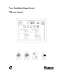
Download User manual - Phason Controls
Transcript
©2012 Phason Inc. All rights reserved. Printed in Canada 21040204 2012-01-16 How to use this manual This section is a ‘quick-reference guide’ of the manual. You can look at the chart on the next page to help you find what you are looking for. If you are not sure where to find something specific, look in the Table of contents at the front of the manual, or the Index on page 81. Below are some helpful suggestions. If you are just starting with SupraWare, read Chapter 1: Introducing SupraWare on page 7. If you are configuring Supras, read Chapter 2: Configuring Supras on page 19. If you are programming Supras or adjusting settings (set points, growth curves, fan speeds, etc.), read Chapter 3: Programming your site on page 38. If you are creating charts or reports, read Chapter 4: Monitoring your site on page 65. Quick reference chart SupraWare overview Computer requirements Installation SupraWare windows Chapter 1 Starting on page 7 Configuration instructions Zone, probe, and sensor assignments Variable and relay stage assignments Chapter 3 Starting on page 19 Programming instructions Group settings (set points and growth curves) Equipment settings (set points, fan speeds, and so on) Alarm settings (bias, duration, silencing, and so on) Chapter 4 Starting on page 38 Monitoring instructions Charts Reports Chapter 5 Starting on page 65 i Limited warranty Software Phason Inc. (Phason) warrants for a period of 90 days from the date of purchase that the software product will execute its programming instructions when properly installed on the personal computer or workstation indicated on this package. Phason does not warrant that the operation of the software will be uninterrupted or error free. Should this software product fail to execute its programming instructions during the warranty period, the purchaser’s remedy shall be to return the software CD (media) to Phason for replacement. Should Phason be unable to replace the media within a reasonable amount of time, the purchaser’s alternate remedy shall be a refund of the purchase price upon return of the product and all copies. Media Phason warrants the media upon which this product is recorded to be free from defects in materials and workmanship under normal use for a period of 90 days from the date of purchase. Should the media prove to be defective during the warranty period, the purchaser’s remedy shall be to return the media to Phason for replacement. Should Phason be unable to replace the media within a reasonable amount of time, the purchaser’s alternate remedy shall be a refund of the purchase price upon return of the product and all copies. Notice of warranty claims The purchaser must notify Phason in writing of any warranty claim no later than 30 days after the warranty period expires. Limitation of warranty Phason makes no other express warranty, whether written or oral, with respect to this product. Any implied warranty of merchantability or fitness is limited to the 90 days of this written warranty. Some states or provinces do not allow limitations on how long an implied warranty lasts, so the above limitation or exclusion may not apply to you. This warranty gives specific legal rights and you may have other rights, which vary from state to state, or province to province. Exclusive remedies The remedies provided above are the purchaser’s sole and exclusive remedies. Phason shall not be liable for any direct, indirect, special, incidental, or consequential damages (including lost profit) whether based on warranty, contract, tort, or any other legal theory. Some states or provinces do not allow the exclusion or limitation of incidental or consequential damages, so the above limitation or exclusion may not apply to you. Warranty service Warranty service may be obtained from the Phason office location indicated in the user manual or service booklet. ii Service and technical support Phason will be happy to answer all technical questions that will help you use SupraWare. Before contacting Phason, collect the following information: Read this manual for information about the feature with which you are having trouble. If you see an alarm message and are not sure what it means, look it up in Troubleshooting section of the Supra user manual and then follow the instructions for resolving the condition. If you are having a problem using the Supra, see if the problem is described in the Troubleshooting section of the Supra user manual and then follow the directions for correcting the problem. If you still have a problem with the Supra or SupraWare, collect the following information: A description of the problem A description of what you were doing before the problem occurred The model(s) and serial number(s) of the devices Any messages displayed by the software My dealer’s name: How to contact my dealer: Street/PO Box City State/Province Zip/Postal Phone Fax E-mail Web site 2 Terracon Place Winnipeg, Manitoba Canada R2J 4G7 Phone Fax E-mail Web site 204-233-1400 204-233-3252 [email protected] www.phason.ca iii About the manual This manual describes the features of SupraWare and how to use them. In addition to reading this manual, you should be familiar with the following. Microsoft Windows™ – how to perform basic Windows functions such as opening and closing windows, finding and opening files, saving and closing files, as well as using a mouse and keyboard. The Supra control and the equipment connected to it Styles The following styles are used in the manual. All buttons and tabs are bolded. For example, click OK to save the changes. All filenames and directories are in a monospace font. For example, the reports directory in Windows Vista is C:\Users\<username>\Documents \phason\OmniSelect\Reports\. Hint/tip This is a hint or tip. It contains helpful information that might make it easier for you to set up or use the SupraWare. Note This is a note. It contains information that may help you better understand the SupraWare. A copy of the manual is also on the installation CD. You can find the manual in the Start menu > All programs > Phason > SupraWare. iv Table of contents Chapter 1: Introducing SupraWare ................................................................................................ 7 Introducing SupraWare ............................................................................................................................. 7 SupraWare features .............................................................................................................................. 7 Getting started........................................................................................................................................... 7 Connecting Supras to your computer .................................................................................................. 8 Installing SupraWare............................................................................................................................. 8 Registering SupraWare ......................................................................................................................... 8 Testing communication between Supras ........................................................................................... 12 SupraWare Windows .............................................................................................................................. 14 Chapter 2: Configuring Supras .................................................................................................... 19 Understanding the structure and configuration of your site ................................................................... 19 Configuring your site ............................................................................................................................... 22 Configuring your farm information...................................................................................................... 23 Adding and removing buildings ......................................................................................................... 24 Configuring the Supras ........................................................................................................................... 26 Adding and removing Supras ............................................................................................................. 26 Adding and removing zones............................................................................................................... 28 Configuring variable stages ................................................................................................................ 29 Configuring relays for actuators ......................................................................................................... 30 Configuring relays for single-stage heating and cooling or temperature-based duty cycles ............ 32 Configuring relays for curtains............................................................................................................ 33 Configuring relays for time-based duty cycles ................................................................................... 34 Configuring relays for timed events .................................................................................................... 36 Testing configuration .......................................................................................................................... 37 Selecting a humidity zone .................................................................................................................. 37 Chapter 3: Programming your site ............................................................................................... 38 Programming Supras .............................................................................................................................. 38 Programming zones ................................................................................................................................ 39 Setting the group set point ................................................................................................................. 40 Programming growth curves .............................................................................................................. 41 Programming the humidity compensation ......................................................................................... 44 Programming variable and relay stages ................................................................................................. 46 Programming variable stages ............................................................................................................. 46 Programming actuators ...................................................................................................................... 50 Programming curtain control relays ................................................................................................... 52 Programming heating and cooling elements and temperature-based duty cycles ........................... 55 Programming timed events ................................................................................................................ 58 Programming time-based duty cycles ................................................................................................ 59 Programming alarms .............................................................................................................................. 61 Chapter 4: Monitoring your site .................................................................................................... 65 Monitoring the status of your site............................................................................................................ 65 Monitoring the Communication Center .............................................................................................. 65 Monitoring the Diagnostics display .................................................................................................... 67 Creating reports and charts .................................................................................................................... 67 Creating reports .................................................................................................................................. 68 Selecting dates ................................................................................................................................... 72 v Creating charts.................................................................................................................................... 72 Zooming and panning charts ............................................................................................................. 74 vi Chapter 1: Introducing SupraWare This chapter introduces you to SupraWare and the layout of the manual. Read chapter 1 before reading the rest of the manual. Introducing SupraWare Getting started SupraWare Windows Introducing SupraWare SupraWare allows you to configure and monitor all the Supra controls at your site from a computer. You can connect up to 32 Supra controls together at distances up to 4000 feet (1220 metres). SupraWare eliminates the need to go to a control to check settings or make changes, you can do it all from one location. SupraWare's easy-to-read displays show you control settings, temperatures, and alarms. The software maintains logs of temperatures, alarms, and system changes and includes four reports and a chart to help you analyze the information. SupraWare features Convenient, easy-to-use displays Control and status information displays Enhanced data logging Four reports, one chart Backup and restore utility Getting started Before you can use SupraWare, you need to connect the Supras to your computer, and install and register the software. 2012-01-16 7 Chapter 1: Introducing SupraWare Connecting Supras to your computer To connect Supras to your computer, you need three things. RS485-FD Converter allows Supras to communicate with your computer. Termination Module (part number 210510) installs on the last Supra on the channel and tells the computer there are no more Supras after that one. Communication cable carries the communication signals between the Supra and RS485-FD Converter Unshielded twisted pair (UTP), category 3 (CAT3) or category 5 (CAT5) Shielded twisted pair (STP), CAT3 or CAT5 Connect the Supras to your computer using the above items. Follow the instructions in the installation guides. For more information, contact your dealer or Phason. Installing SupraWare SupraWare has an installation wizard that guides you through the installation. To install SupraWare 1. Insert the CD into your computer’s CD-ROM drive. The Installation Wizard should start automatically. If it does not start automatically, find and start the file Inst_SupraWare.exe on the CD-ROM. 2. Follow the instructions on the screen. Registering SupraWare Before you can use SupraWare, you need to register the software. Registering SupraWare means entering your information and obtaining a product key. There are three registration methods. Web (online registration): allows you to register and get your product key over the Internet. Web registration is available 24 hours a day, 7 days per week. Fax or mail: allows you to print the registration information and then fax or mail it to Phason. When we receive your information, we will contact you with your product key. 8 Phason Getting started Phone: allows you to call Phason to get your product key. Phone registration is available from 8:00 AM to 4:30 PM, Monday to Friday, excluding holidays. The first time you start SupraWare, the Software Registration Wizard displays. A B A C This is where you enter the serial number that is printed on your CD. B These buttons allow you to move back and forth through the registration windows. C When available, this button registers and enables SupraWare. To register over the Internet (web registration) 1. On the Communication Center, click Login. The Software Registration Wizard displays. 2. Beside Serial number, type the last six digits of the serial number printed on your installation CD. 3. Click Next. The Registration Wizard displays the license terms and conditions. 4. Read the license agreement and then select I Agree. 5. Click Next. The Registration Wizard displays the registration options. 6. Click Register on the Web. Your web browser opens to the Phason registration page. 7. Enter your information in the web form and then click Next. 9 Phason Chapter 1: Introducing SupraWare Your web browser displays your registration information, including the product key you need to enter in the Registration Wizard. 8. Click Select product key. 9. On your keyboard, press CTRL+C to copy the product key. 10. On the Registration Wizard, beside Product key, press CTRL+V to paste the product key. The Enable software button should become available. If the button does not become available, delete all the information beside Product key and then repeat steps 8 to 10. 11. Click Enable software. The Information window displays 12. Click OK to close the Information window. 13. Click Exit to close the Registration Wizard. To register by fax, mail, or e-mail 1. On the Communication Center, click Login. The Software Registration Wizard displays. 2. Beside Serial number, type the last six digits of the serial number printed on your installation CD. 3. Click Next. The Registration Wizard displays the license terms and conditions. 4. Read the license agreement and then select I Agree. 5. Click Next. The Registration Wizard displays the registration options. 6. Click Print for fax or mail. The Registration Wizard displays the registration form. 10 Phason Getting started 7. Enter your information in the form and then click Print preview. The Registration information window displays your information. 8. Print your information so you can register by fax or mail, or save it so you can register by e-mail. 9. Send your registration information to Phason. When you receive your product key, return to the Registration Wizard. 10. Beside Product key, type the product key given to you by Phason. The Enable software button should become available. If the button does not become available, make sure you typed all the numbers correctly. 11. Click Enable software. The Information window displays 12. Click OK to close the Information window. 13. Click Exit to close the Registration Wizard. To register by phone 1. On the Communication Center, click Login. The Software Registration Wizard displays. 2. Beside Serial number, type the last six digits of the serial number printed on your installation CD. 3. Click Next. The Registration Wizard displays the license terms and conditions. 4. Read the license agreement and then select I Agree. 5. Click Next. The Registration Wizard displays the registration options. 6. Click Register by phone. The Registration Wizard displays the information you need to give Phason. 11 Phason Chapter 1: Introducing SupraWare 7. Call Phason and give them your information. 8. Beside Product key, type the product key given to you by Phason. The Enable software button should become available. If the button does not become available, make sure you typed all the numbers correctly. 9. Click Enable software. The Information window displays 10. Click OK to close the Information window. 11. Click Exit to close the Registration Wizard. Testing communication between Supras Before you start using SupraWare, you need to make sure SupraWare is communicating with all the Supras. When you start SupraWare, the software looks for any Supras connected to the computer and displays the addresses of the Supras in the message area. 12 Phason Getting started Supra addresses are listed here Supra names (IDs) are listed here If all the Supras are listed, you can start to configure and set up the controls. If not all of the Supras are listed, you need to check the communication wiring for those Supras. For more information, read Connecting Supras to your computer on page 8. You must have at least one Supra connected to your computer before you can start configuring and using the software. You can use Test Bench Ultra to troubleshoot communication problems between the Supras. You can find Test Bench Ultra in the Start menu under Phason. 13 Phason Chapter 1: Introducing SupraWare SupraWare Windows SupraWare has several Communication Centers you need to become familiar with. The diagram below shows the layout of the windows and their main functions. Communication Center Audit and alarm messages Control status Configuration Manager Settings Manager Reports Manager Utilities Manager Configuration Manager Settings Manager Reports Manager Utilities Manager Configuration for: - site - buildings - Supras - control elements Programming for: - Supras - zones - control elements Supra Data Report Audit History Report Alarm History Report Settings and Configuration Supra Data Chart Backup and Restore Utility Purge Data Utility Diagnostics Utility Communication Center The Communication Center is the Communication Center for SupraWare. From the Communication Center, you can get to all other windows. The buttons on the left side of the window open other windows of the program. The Communication Center displays information about the system and the Supras connected to it, including: Status information, for example, current temperatures, humidity Audit information, for example, system changes, configuration changes, program startup or shutdown Alarm information, for example, high temperature, actuator jam 14 Phason SupraWare Windows Opens the Settings Manager Opens the Configuration Manager Opens the Reports Manager Opens the Utilities Manager SupraWare must always be running. SupraWare collects, displays, and stores information only when it is running. When SupraWare is not running, the Supras will function according to their settings, but new settings cannot be sent. Configuration Manager The Configuration Manager is where you create the framework for your site. From the Configuration Manager, you can: Configure your farm information Add or remove buildings, Supras, and zones Add, remove, or configure control elements (variable stages, relay stages, actuators, and so on) For more information, read Chapter 2: Configuring Supras on page 19. The left panel shows what is currently configured at your site. The right panel shows items (buildings, controls, zones, and control elements) that you can add to the item that is selected in the left panel. For example, if you select a Supra in the left panel, the right panel displays zones and control elements. 15 Phason Chapter 1: Introducing SupraWare Settings Manager The Settings Manager is where you program the settings for your site. From the Settings Manager, you can: Program the zones (temperature set point, growth curves, and humidity compensation) Program the variable and relay stages (fans, heaters, actuators, timed events, and so on) Program the alarm settings (high and low temperature set points, biasing, duration, and so on) For more information, read Chapter 3: Programming your site on page 38. The left panel shows what is currently configured at your site. The right panel shows the settings for the selected item from left panel. For example, if you select a variable speed fan in the left panel, the right panel displays the settings for the fan. 16 Phason SupraWare Windows Reports Manager The Reports Manager is where you create charts and reports. Utilities Manager The Utilities Manager is where you back up, restore, or purge data from SupraWare, and can view the status of Supras. 17 Phason Chapter 1: Introducing SupraWare 18 Phason Chapter 2: Configuring Supras Chapter 2 explains how to configure Supras using SupraWare. Configuring Supras includes telling them which equipment is connected to each terminal. Understanding the structure and configuration of your site Configuring your site Configuring the Supras Understanding the structure and configuration of your site In SupraWare, your site is made up of several different components: buildings, Supras, zones, and equipment. This section explains how these components relate to each other. Phancy Pharms Site/Farm North Finisher Building NW Finisher Supra Outdoor temp. Water meter NW Fin1 Mister Actuator Heater Zone NW Fin2 Fan Mister Heater Actuator Equipment Fan Humidity sensor 2012-01-16 19 Chapter 2: Configuring Supras Site The site/farm is the "top of the chain" and "owns" everything beneath it. Buildings Buildings represent barns at your site. A site can have one or many buildings. Buildings "belong" to the site. Supras Supras belong to the building in which they are assigned. Supras own the zones and equipment assigned to them. Time-based elements, such as timed events and time-based duty cycles can be assigned directly to a Supra and do not need to be assigned to a zone. Zones Zones are sections of buildings or rooms. Each zone has a target temperature, called the group set point. Zones can be physically separated, such as rooms, or can be areas of one large room. For example, a large room could be divided into two zones to provide better control response. Each Supra can have up to four zones, which belong to that specific Supra. All temperature-based elements, such as variable stages, heat-cool stages, actuator stages, and so on, must be assigned to a zone. A zone owns all the equipment assigned to it. Example 1: two rooms, two zones You have a large finisher barn divided into two rooms. You have a forced-air ventilation system that consists of fans and inlets. You will use one Supra to control both rooms, one zone per room. The configuration could be as follows. Room Zone Ventilation stage Supra output Equipment Room 1 Room 1 Room 1 Room 1 Room 1 Room 1 Room 1 Room 1 Room 2 Room 2 Room 2 Room 2 Room 2 Room 2 Room 2 Room 2 Zone 1 Zone 1 Zone 1 Zone 1 Zone 1 Zone 1 Zone 1 Zone 1 Zone 2 Zone 2 Zone 2 Zone 2 Zone 2 Zone 2 Zone 2 Zone 2 Stage 1 Stage 2 Stage 3 Stage 4 Stage 5 — — — Stage 1 Stage 2 Stage 3 Stage 4 Stage 5 — — — VAR 1 VAR 2 RLY 1 RLY 2 RLY 3 RLY 4 RLY 5 RLY 6 VAR 3 VAR 4 RLY 7 RLY 8 RLY 9 RLY 10 RLY 11 RLY 12 Two 20-inch, variable-speed fans Three 25-inch, variable-speed fans Two 36-inch, single-speed fans One 48-inch, single-speed fan Two 48-inch, single-speed fans Gas-fired furnace Inlet actuator OPEN Inlet actuator CLOSE Two 20-inch, variable-speed fans Three 25-inch, variable-speed fans Two 36-inch, single-speed fans One 48-inch, single-speed fan Two 48-inch, single-speed fans Gas-fired furnace Inlet actuator OPEN Inlet actuator CLOSE 20 Phason Understanding the structure and configuration of your site Example 2: one room, two zones You have a large, single-room finisher barn. You have a forced-air ventilation system consisting of fans and inlets. You will use one Supra to control the barn. Because the room is very large, you will use two zones. The configuration could be as follows. Room Zone Ventilation stage Supra output Equipment Room 1 Room 1 Room 1 Room 1 Room 1 Room 1 Room 1 Room 1 Room 1 Room 1 Room 1 Room 1 Room 1 Room 1 Room 1 Room 1 Zone 1 Zone 1 Zone 1 Zone 1 Zone 1 Zone 1 Zone 1 Zone 1 Zone 2 Zone 2 Zone 2 Zone 2 Zone 2 Zone 2 Zone 2 Zone 2 Stage 1 Stage 2 Stage 3 Stage 4 Stage 5 — — — Stage 1 Stage 2 Stage 3 Stage 4 Stage 5 — — — VAR 1 VAR 2 RLY 1 RLY 2 RLY 3 RLY 4 RLY 5 RLY 6 VAR 3 VAR 4 RLY 7 RLY 8 RLY 9 RLY 10 RLY 11 RLY 12 Two 20-inch, variable-speed fans Three 25-inch, variable-speed fans Two 36-inch, single-speed fans One 48-inch, single-speed fan Two 48-inch, single-speed fans Gas-fired furnace Inlet actuator OPEN Inlet actuator CLOSE Two 20-inch, variable-speed fans Three 25-inch, variable-speed fans Two 36-inch, single-speed fans One 48-inch, single-speed fan Two 48-inch, single-speed fans Gas-fired furnace Inlet actuator OPEN Inlet actuator CLOSE Configuration checklist Because some items need to be configured before others, we recommend configuring the Supra in the following order. If you do not have elements of a particular type, skip that step. For example, if you do not have actuators, skip to the next step. The Supra user manual has a similar configuration checklist. Any items listed on the Supra configuration checklist, but not on the SupraWare configuration checklist, cannot be done from SupraWare and must be done at the Supra. For more information, see the Supra user manual. Configuring your site Configuring your farm information (SupraWare only) Adding and removing buildings (SupraWare only) Configuring Supras Adding and removing Supras (SupraWare only) Adding and removing zones (SupraWare only) 21 Phason Chapter 2: Configuring Supras Configuring variable and relay stages Configuring variable stages Configuring relays for actuators Calibrating actuators (Supra only) Configuring relays for single-stage heating and cooling or temperature-based duty cycles Configuring relays for curtains Configuring relays for time-based duty cycles Configuring relays for timed events System configuration Selecting motor curves (Supra only) Configuring temperature averaging (Supra only) Selecting a humidity zone Configuring hysteresis (Supra only) Configuring warnings (Supra only) Testing configuration (Supra only) We recommend configuring all your control elements before programming the settings (temperature set points, idle speeds, and so on). Use the Installation worksheets in the back of the Supra user manual to help you keep track of which equipment is connected to which relays and variable stages. If you receive a warning during configuration, look it up in the Troubleshooting section of the Supra user manual and then follow the instructions for correcting the problem. The Supra’s built-in diagnostic tests are useful for testing your equipment after installing and configuring it. For more information, read the Supra user manual. Configuring your site Configuring your site means naming the site, choosing site-wide options, adding buildings, and adding Supras. You need to configure your site before you can configure Supras. 22 Phason Configuring your site Configuring your farm information Configuring your farm means naming the site and configuring site-wide options, including information is displayed, the data recording interval, and more. Farm name and location The name you enter for your farm is displayed in the software and on all charts and reports. Temperature and water units The units of measure you select for temperature and water determine how you display information in the software and the charts and reports. To display water usage information, you must have a water meter connected to the Supra. For more information, read the Installation section of the Supra user manual. Data recording interval SupraWare reads information (temperature, water, humidity) from the Supras each minute. The data recording interval determines how often SupraWare stores the information. The default is every ten minutes. This means every ten minutes there will be an entry in the SupraWare data file for each Supra. This is not the same as the logging interval for the Supra. For more information about the logging interval, see the Supra user manual. Warnings Warnings are one of SupraWare’s built-in diagnostic tools. They warn you about conflicts or out-ofrange conditions as you are programming the control. When you enable warnings in SupraWare, if you enter settings that could cause a problem, SupraWare displays a dialog box similar to the one below. 23 Phason Chapter 2: Configuring Supras For more information about the types of warnings, see the appendix in the Supra user manual. When you enable warnings in SupraWare, you enable all warnings for all Supras. To configure your farm information 1. In the Communication Center, click Configuration. The Configuration Manager displays. 2. Right-click the tractor icon. The Farm Information window displays. 3. Make changes to the farm settings. To change the Farm name or location, beside either of those items, type the new information. To change the unit of measure for temperature or water usage, beside either of those items, select the unit you want to use the display information in SupraWare. To change the data recording interval, select how often you want SupraWare to store information in the data files. To enable or disable warnings, select or deselect Enabled. There is a checkmark in the box when enabled. 4. Click OK to save the information and return to the Configuration Manager. Adding and removing buildings After configuring your site, you need to add buildings to it. A building represents a barn at your site. 24 Phason Configuring your site To add buildings 1. In the Communication Center, click Configuration. The Configuration Manager displays. 2. Click and drag the building icon over to the tractor icon and then drop it. You must drop it on the tractor icon. The Building Properties window displays. 3. Type a name/description for the building and then click OK. 4. Click OK to save the information and return to the Configuration Manager. To rename buildings To rename a building, right-click on the existing building, type a new name, and then click OK. To remove buildings Before removing a building, you must remove all the control elements, zones, and Supras belonging to that building. For more information, read Configuring the Supras on page 26. 1. In the Communication Center, click Configuration. The Configuration Manager displays. 2. Select the building you want to remove and then press DELETE. A confirmation window displays. 3. Click Yes to remove the building, or No to cancel and return to the Configuration Manager. 25 Phason Chapter 2: Configuring Supras Configuring the Supras Configuring Supras means adding them to SupraWare, adding zones, and configuring the variable and relay stages. For example, each Supra has 12 relay stages. You need to configure the stages to control curtains, heating or cooling elements, or timed events. In addition, you need to assign the stages to a zone. Before you configure the Supras, make sure: They have power All equipment has been properly connected to the correct terminals You know which equipment is connected to which relays and variable stages If you configured the Supras before installing SupraWare, you do not need to reconfigure them. Add the Supras to the corresponding buildings and then all your configuration and settings automatically transfer into SupraWare. Each Supra user manual contains configuration worksheets to help you determine what the configuration should be and what values need to be set up for each element. Use these worksheets when configuring and programming Supras using SupraWare. For information about set points, idle speeds, or other settings, read Chapter 3: Programming your site on page 37. Adding and removing Supras After adding buildings, you can add Supras to the buildings. When the Supras were installed, the installer should have written down the address on the installation sheets found in the Supra user manual. If you do not have the addresses written down you will have to go to each Supra to find its address. For more information, read the installation section of the Supra user manual. To add Supras 1. In the Communication Center, click Configuration. The Configuration Manager displays. 2. Below Buildings and Controls, click and drag the Supra icon to the building it belongs in. The Add a New Control window displays. 26 Phason Configuring the Supras 3. Below Control Address, type the address of the Supra exactly as it appears on the control. 4. Below Control Name, type a descriptive name for the Supra. 5. Click OK to add the Supra. An information window displays. 6. Click OK to return to the Configuration Manager. To remove Supras Before removing a Supra, you must remove all the zones and control elements belonging to that Supra. 1. In the Communication Center, click Configuration. The Configuration Manager displays. 2. Select the Supra you want to remove and then press DELETE. A confirmation window displays. 3. Click Yes to remove the Supra, or No to cancel and return to the Configuration Manager. 27 Phason Chapter 2: Configuring Supras Adding and removing zones Zones are sections of buildings or rooms. Each zone has a target temperature, called the group set point. Zones can be physically separated, such as rooms, or they can be areas of one large room. For example, a large room could be divided into two zones to provide better control response. Each Supra can have up to four zones. All temperature-based elements (for example, variable stages, heat/cool stages, actuator stages) must be assigned to a zone. For more information about zones, see Understanding the structure and configuration of your site on page 19. To add zones 1. In the Communication Center, click Configuration. The Configuration Manager displays. 2. Below Buildings and Controls, click and drag the zone icon to the Supra it belongs in. A new zone appears in the list under the Supra. To remove zones Before removing a zone, you must remove all the control elements belonging to that zone. 1. In the Communication Center, click Configuration. The Configuration Manager displays. 2. Select the zone you want to remove and then press DELETE. A confirmation window displays. 3. Click Yes to remove the zone, or No to cancel and return to the Configuration Manager. 28 Phason Configuring the Supras Configuring variable stages Each variable stage (VAR1 to VAR4) can control elements that operate with gradually increasing voltage, such as variable speed fans, or gradually decreasing voltage, such as heat mats. Heat mat example Decreased heat Increased speed Variable-speed fan example Increase voltage Decrease voltage Configuring a variable stage means assigning it to a zone, selecting whether it is a heating or cooling element, and assigning it a descriptive name. For more information about how variable stages work, read Programming variable stages on page 46. To configure variable stages If you want to move a stage to a different zone, click and drag the stage to the zone you want it in. 1. In the Communication Center, click Configuration. The Configuration Manager displays. 2. Below System Configuration, select the Supra and zone for the variable stage. 3. If the stage has not been added to the zone, below Zones and Stages, click and drag the stage to the zone it belongs in. 4. Below System Configuration, right-click the variable stage you want to configure. The Variable Stage Properties window displays. 5. Beside Name, type a descriptive name for the stage. 29 Phason Chapter 2: Configuring Supras 6. Below Mode, select the configuration for the stage. 7. Click OK to save the information and return to the Configuration Manager. To remove variable stages 1. In the Communication Center, click Configuration. The Configuration Manager displays. 2. Select the stage you want to remove and then press DELETE. A confirmation window displays. 3. Click Yes to remove the stage, or No to cancel and return to the Configuration Manager. Configuring relays for actuators You can connect up to two actuators to a Supra. Each actuator you connect requires two relays: one for extending the actuator arm (opening the inlet), and one for retracting the arm (closing the inlet). You can connect actuators to any available relays, but side-by-side relays are recommended. For each actuator, you need to know the following: Which relay the actuator is connected to for opening the inlet Which relays the actuator is connected to for closing the inlet Which feedback terminal the actuator is connected to; FB1 for Actuator 1, FB2 for Actuator 2. 30 DO NOT switch on power to an actuator until you have calibrated the actuator and set the limit switches. Switching on the power to the actuator before completing these steps can damage the actuator or the actuator power supply. For more information, read the configuring actuators section of the Supra user manual. Phason Configuring the Supras To configure relays for actuators 1. In the Communication Center, click Configuration. The Configuration Manager displays. 2. Below System Configuration, select the Supra and zone for the actuator. 3. Below Zones and Stages, click and drag the actuator to the zone it belongs in. The Relay Selection window displays. 4. Select the relay for opening the actuator and then click OK. 5. Select the relay for closing the actuator and then click OK. 6. Below System Configuration, right-click the actuator. The Actuator Properties window displays. 7. Beside Name, type a descriptive name for the actuator. 8. Click OK to save the information and return to the Configuration Manager. To remove actuators 1. In the Communication Center, click Configuration. The Configuration Manager displays. 2. Select the actuator you want to remove and then press DELETE. A confirmation window displays. 3. Click Yes to remove the actuator, or No to cancel and return to the Configuration Manager. 31 Phason Chapter 2: Configuring Supras Configuring relays for single-stage heating and cooling or temperature-based duty cycles Relays configured for heating can control equipment as electric or gas heaters that can be either on or off. The relays switch on when the temperature drops below the set point and off when it rises above. Relays configured for cooling can control single-speed fans, misters, or other cooling equipment that can be either on or off. The relays switch on when the temperature rises above the set point and off when it drops below. This section is for ON/OFF relays. For information about variable-powered heating and cooling elements, read Configuring variable stages on page 29. If you need to connect more cooling elements than you have relays, and you are not using all the variable stages, you can use any available variable stages as ON/OFF stages. For more information, read Programming variable stages on page 46. To configure single-stage heating and cooling relays or temperature-based duty cycles 1. In the Communication Center, click Configuration. The Configuration Manager displays. 2. Below System Configuration, select the Supra and zone for the stage. 3. If the stage has not been added to the zone, below Zones and Stages, click and drag the stage to the zone it belongs in. 4. Below System Configuration, right-click the stage you want to configure. The Properties window displays. 5. Beside Name, type a descriptive name for the stage. 6. Below Mode, select the configuration for the stage. 7. Click OK to save the information and return to the Configuration Manager. 32 Phason Configuring the Supras To remove single-stage heating and cooling relays or temperature-based duty cycles 1. In the Communication Center, click Configuration. The Configuration Manager displays. 2. Select the stage you want to remove and then press DELETE. A confirmation window displays. 3. Click Yes to remove the stage, or No to cancel and return to the Configuration Manager. Configuring relays for curtains Curtains are usually controlled by equipment called curtain machines, which are often called winches. Curtains open or close to let in more air or less air, with the idea that more air cools the building. You can connect up to six curtain machines to a Supra. Each curtain machine requires two relays: one for opening, one for closing the curtain. You can connect curtain machines to any of the available relays, but side-by-side relays are recommended. To configure relays for curtains 1. In the Communication Center, click Configuration. The Configuration Manager displays. 2. Below System Configuration, select the Supra and zone for the curtain. 3. Below Zones and Stages, click and drag a curtain to the zone it belongs in. The Relay Selection window displays. 4. Select the relay for opening the curtain and then click OK. 33 Phason Chapter 2: Configuring Supras 5. Select the relay for closing the curtain and then click OK. 6. Below System Configuration, right-click the curtain. The Curtain Properties window displays. 7. Beside Name, type a descriptive name for the curtain. 8. Click OK to save the information and return to the Configuration Manager. To remove curtains 1. In the Communication Center, click Configuration. The Configuration Manager displays. 2. Select the curtain you want to remove and then press DELETE. A confirmation window displays. 3. Click Yes to remove the curtain, or No to cancel and return to the Configuration Manager. Configuring relays for time-based duty cycles Time-based duty cycles allow you to have equipment operate for specific durations during certain hours of the day. For example, you can have a feed auger run for 15 minutes and then stop for 45 minutes between 6:00 AM and 8:00 PM. 34 This section explains how to configure time-based duty cycles. If you want to configure temperature-based duty cycles (duty cycles that while the temperature is above or below a certain value), read Configuring relays for single-stage heating and cooling or temperature-based duty cycles on page 32. If you want to configure elements that turn on and off at specific times, read Configuring relays for timed events on page 36. Phason Configuring the Supras To configure relays for time-based duty cycles 1. In the Communication Center, click Configuration. The Configuration Manager displays. 2. Below System Configuration, select the Supra for the relay. 3. Below Zones and Stages, click and drag the relay to the Supra it belongs in. You must drop it on the Supra, not a zone. 4. Below System Configuration, right-click the relay you want to configure. The Properties window displays. 5. Beside Name, type a descriptive name for the relay. 6. Below Mode, select Duty Cycle. 7. Click OK to save the information and return to the Configuration Manager. To remove time-based duty cycles 1. In the Communication Center, click Configuration. The Configuration Manager displays. 2. Select the duty cycle you want to remove and then press DELETE. A confirmation window displays. 3. Click Yes to remove the duty cycle, or No to cancel and return to the Configuration Manager. 35 Phason Chapter 2: Configuring Supras Configuring relays for timed events Relays configured for timed events can be used to control feed augers, lights, or other equipment that must operate at specific times each day, regardless of temperature. An example of a timed event would be would be switching the yard lights on at 8:00 PM and off at 7:00 AM. To configure relays for timed events 1. In the Communication Center, click Configuration. The Configuration Manager displays. 2. Below System Configuration, select the Supra for the relay. 3. Below Zones and Stages, click and drag the relay to the Supra it belongs in. You must drop it on the Supra, not a zone. 4. Below System Configuration, right-click the relay you want to configure. The Properties window displays. 5. Beside Name, type a descriptive name for the relay. 6. Below Mode, select Time Events. 7. Click OK to save the information and return to the Configuration Manager. To remove timed events 1. In the Communication Center, click Configuration. The Configuration Manager displays. 2. Select the timed event you want to remove and then press DELETE. A confirmation window displays. 3. Click Yes to remove the timed event, or No to cancel and return to the Configuration Manager. 36 Phason Configuring the Supras Testing configuration After you configure all control elements (variable stages, relays, and so on), test the Supra to make sure the configuration is correct. In other words, make sure what you think is connected to a specific relay or stage is actually connected to that relay or stage. Test the configuration by using the diagnostic feature of the Supra. The diagnostic feature allows you to operate the equipment, regardless of temperature or time. As you operate each piece of equipment, visually check to see if that equipment is doing what you tell it. For example, when you switch on VAR 1 (variable stage 1) at the Supra, does the fan or heater you think is connected to that stage switch on? When you switch off VAR 1, does it switch off? For more information about diagnostics, read Servicing and maintaining in the Supra user manual. Selecting a humidity zone If you installed a Relative Humidity Sensor on a Supra, you need to select which zone the sensor will be monitoring. A humidity sensor can monitor only one zone. To add humidity sensor to a zone 1. In the Communication Center, click Configuration. The Configuration Manager displays. 2. Below System Configuration, select the Supra and zone for the humidity sensor. 3. Below Zones and Stages, click and drag the humidity sensor to the zone it belongs in. To remove a humidity sensor from a zone 1. In the Communication Center, click Configuration. The Configuration Manager displays. 2. Select the humidity sensor you want to remove and then press DELETE. A confirmation window displays. 3. Click Yes to remove the humidity sensor, or No to cancel and return to the Configuration Manager. 37 Phason Chapter 3: Programming your site Chapter 3 explains how to enter settings into the Supras. Programming Supras Programming zones Programming variable and relay stages Programming alarms Programming Supras Programming Supras basically means telling the Supras what to do with the equipment connected to them. For a single-speed fan set for cooling, you might say: "Switch on when the temperature rises above 80°F." Because some settings must be programmed before others, we recommend programming the Supra in the following order. If you do not have elements of a particular type, skip that step. For example, if you do not have curtains, go to the next step. Programming zones Setting the group set point Programming growth curves Programming the humidity compensation Programming variable and relay stages Programming variable stages Programming actuators Programming curtain control relays Programming heating and cooling elements and temperature-based duty cycles Programming timed events Programming time-based duty cycles Programming the alarm and display settings Programming alarms (additional alarms at Supra) Setting up the status display (Supra only) Setting up the logging interval (Supra only) 2012-01-16 38 Programming zones Before you begin programming Supras, make sure: They have power All equipment has been properly connected to the correct terminals You know which equipment is connected to which relays and variable stages All variable and relay stages have been properly configured and tested. For more information, read Chapter 2: Configuring Supras on page 19. DO NOT program the Supras with the keypad and SupraWare at the same time. Choose one method or the other. Each Supra user manual contains programming worksheets to help you determine what the programming should be and what values need to be set up for each element. Use these worksheets when programming Supras using SupraWare. If you receive a warning during programming, look it up in the Troubleshooting section of the Supra user manual and then follow the instructions for resolving the condition. Programming zones Programming zones means entering the target temperatures for each zone. If you are monitoring humidity, you need to program the humidity limits. There are two options for the zone temperatures. Group set points Growth curves You can set up both group set points and growth curves, but the Supra will use only one. If a growth curve is enabled for a zone, the control uses the growth curve. If there is no growth curve for a zone, it uses the group set points. 39 Phason Chapter 3: Programming your site Setting the group set point A group set point is the desired or target temperature for a zone. Set points for each piece of equipment connected to a variable or relay is adjusted relative to the group set point. Set the group set point before setting the equipment set points. For example, let’s say the set point for zone 1 is 80°F, a variable-stage fan set point is 5° higher (85°F), and a single-stage heater set point is 7° lower (73°F). If you lower the group set point by 5° to 75°F, the set points for the fan and heater will also be lowered by 5° to 80°F and 68°F respectively. A B D E C A This is information about the zone and its control. B This is the current zone temperature. C This is the group set point. You can adjust the set point by clicking the slider and then pressing PAGE UP or PAGE DOWN to change the temperature by 1°, or UP or DOWN to change it by 0.1°. D This is the growth curve selection. If you are using a growth curve, select the curve you are using. If you are using a group set point, select None. E This is where you enable or disable the temperature alarms for the zone. To set a group set point 1. In the Communication Center, click Settings. The Settings Manager displays. 2. Select the Supra and zone you want to program and then click Adjust. The Zone Settings window displays. 40 Phason Programming zones 3. Make the changes to the settings. If you will be using a growth curve, select curve A or B. If you will be using a group set point, select None. To change the group set point, click the slider and then drag up or down. For more precise adjustments, click the slider and then press the UP or DOWN key. To enable or disable the alarms, select or deselect Enabled. There is a checkmark in the box when enabled. 4. Click OK to save the information and return to the Settings Manager. Programming growth curves A growth curve is an extension of the group set point concept. The growth curve automatically adjusts the set points over time to control the temperature in a room or zone. For example, in hog production, newborn piglets require a high temperature for comfort and health. As they grow older, they need a steadily lower temperature. Using the growth curve, you can have the Supra automatically adjust the temperatures. You can start at 76°F for 1 day, drop to 74°F for 1 day, then to 71°F for 21 days, 68°F for 14 days, and so on. You can program two growth curves: Growth Curve A and Growth Curve B. This lets you control two different areas of your facility with each Supra, with each area having independent set points. You can have up to seven steps in a growth curve. Each step has a starting temperature and duration (in days). The Supra automatically calculates the set points for the days between the steps and adjusts the set points at midnight each day. Individual set points for the variable and fixed stages are adjusted relative to the growth curve temperature for that particular day. This is an extremely powerful feature because it lets you put fan and heating strategies in place once, and then adjust them automatically over time. In the following page, step 2 has a duration of 10 days. The difference between the starting set point (86.5°F) and the starting set point for the next step (85°F) is 1.5°F. The Supra divides the temperature difference by the duration 1.5 ÷ 10=0.15 and then automatically adjusts the set point by 0.15°F each day for 10 days. Step 1 2 3 4 5 6 7 41 Temperature (°F) Duration (days) 88.0 86.5 85.0 83.5 81.0 78.0 74.0 5 10 10 10 5 5 10 Phason Chapter 3: Programming your site 90°F Step 1 Step 2 Step 3 Temperature 85°F Step 4 Step 5 80°F Step 6 Step 7 75°F 70°F 65°F Day 1 Day 5 Day 15 Day 25 Day 35 Day 40 Day 45 Day 55 Duration A B C F D E A This is information about the control. B This is the start date and current day for the growth curve. C This is a representation of the growth curve. As you adjust the settings, the graph changes. D This is where you adjust the temperature set points for the steps. You can adjust the set point by clicking the slider and then pressing PAGE UP or PAGE DOWN to change the temperature by 1°, or UP or DOWN to change it by 0.1°. 42 Phason Programming zones E This is where you adjust the duration for the steps. F This is the status of the growth curve. Before defining growth curves, assign the zones that will be controlled according to the curves. For more information, read Setting the group set point on page 40. To define growth curves 1. In the Communication Center, click Settings. The Settings Manager displays. 2. Select the Supra you want to program and then click Growth Curve A or Growth Curve B, whichever one you want to program. The Growth Curve Settings window displays. 3. Below Starting Date, select the date to growth curve will start. For more information about selecting dates, see Selecting dates on page 72. 4. Below Step 1, click the temperature slider and then press PAGE UP or PAGE DOWN to change the temperature by 1°, or UP or DOWN to change it by 0.1°. 5. Below Step 1 click the duration slider and then press LEFT or RIGHT to change the duration. 6. Repeat steps 4 and 5 for each step. 7. Below Status, select the current status of the growth curve. The following table describes each choice. Setting Description Disabled Enabled Suspended This growth curve is ignored. This growth curve is active for the zones specified. All set points will stay at their current values, and the growth curve will remain on its current day, until it is enabled again. When enabled, it will pick up where it left off. This growth curve will still advance one day at a time, but all the set points will be determined by the user-entered group set point. When enabled, the group set point will jump to the growth curve set point for that day. This may result in a sudden change in temperature if the user’s set point is very different from the growth curve set point. Override If you are programming your growth curve a few days before you want it to start, set the status to disabled. In the day you want to start the growth curve, change the status to enabled. 8. Click OK to save the information and return to the Settings Manager. 43 Phason Chapter 3: Programming your site Programming the humidity compensation If you have installed and configured a humidity sensor, you need to program the humidity compensation. Programming the humidity compensation means setting the humidity factor and the upper and lower humidity limits. The humidity band is the humidity range in which the Supra attempts to compensate for humidity. The humidity factor is a number between 0 and 10 that determines the amount of humidity compensation. A lower value produces a slight ventilation adjustment, while a higher value produces a greater adjustment. How it works The Supra uses the humidity band and factor to adjust the ventilation for the zone. At the beginning of the band (the lower limit), very little adjustment is made. As the humidity rises, the adjustment increases. At or above the upper limit of the band, the maximum adjustment is applied. For example, if the maximum acceptable humidity for your zone is 70%, set the lower limit to 70%. You could set the upper limit to 90% (90% is the maximum allowed and 20% is the minimum difference between the lower and upper limits). When the humidity is below 70%, the ventilation rate is controlled by the zone’s normal, programmed settings. As the humidity rises above 70%, humidity compensation starts to take effect and the ventilation rate increases. When the humidity reaches 90%, the humidity compensation reaches its maximum adjusted rate. If the outside air is cooler than the zone temperature, the ambient temperature in the zone drops due to the increased ventilation. This causes heaters to switch on, which help to dry the air. It is important to balance this effect with your heating system’s ability to maintain the temperature while drying out the room. A lower humidity factor starting at a lower humidity level, and spread over a wider band, is better for lower-capacity heating systems. 44 Phason Programming zones A C B A D This is information about the zone and control. B This is the current temperature and humidity in the zone. C This is the humidity factor (amount of compensation). D This is where you adjust the upper and lower limits. You can adjust the set points by pressing PAGE UP or PAGE DOWN to change the level by 10, or UP or DOWN to change it by 1. To program the humidity compensation 1. In the Communication Center, click Settings. The Settings Manager displays. 2. Select the humidity sensor you want to program and then click Adjust. The Humidity Settings window displays. 3. Below Lower Limit, click the slider and then press PAGE UP or PAGE DOWN to change the level by 1°, or UP or DOWN to change it by 0.1°. Repeat for the Upper Limit. 4. Beside Humidity Factor, click Up or Down to adjust the value. 5. Click OK to save the information and return to the Settings Manager. 45 Phason Chapter 3: Programming your site Programming variable and relay stages Programming stages means entering settings such as temperature set points, idle speeds, ON/OFF times, durations, and so on. Programming variable stages Programming up the variable stages means setting the temperature set points, idle speeds, and so on. There are four settings for each variable stage. For a cooling stage: On full at (sometimes called differential) Idle at (sometimes called set point) Off at (sometimes called idle range) Idle speed For a heating stage: Off at Set point On full at (sometimes called differential) Min heat Before setting up the variable stages, make sure you have properly configured them. For more information, read Configuring variable stages on page 29. How variable cooling stages work When the temperature is below the off at temperature, the fan is off. When the temperature rises above the off at temperature, the fan runs at the idle speed. The fan continues to run at the idle speed until the temperature rises to the idle at temperature. When the temperature is between the idle at and on full at temperatures, fan speed increases or decreases proportionally with temperature. When the temperature is above the on full at temperature, the fan runs at full speed. 46 Phason Programming variable and relay stages The fan runs at full speed On full at Fan speed increases as the temperature rises, or decreases as the temperature falls. Temperature Idle at The fan runs at idle speed Off at The fan is off Idle speed Fan speed If you need to connect more cooling elements than you have relays, and you are not using all the variable stages, you can use any available variable stage as an ON/OFF stage. Set the idle speed to 100% and off at to the temperature at which you want the stage to switch on/off. You no longer have "variable" speed or power; you have either "full on" or "full off", the same as a regular cooling element. The idle at and on full at settings have no effect when you use a variable stage this way. How variable heating stages work When the temperature is above the off at temperature, the heater is off. When the temperature drops below the off at temperature, the heater is at the min heat output. The heater continues to operate at the min heat until the temperature drops to the set point. When the temperature is between the set point and the on full at temperatures, the heater output increases or decreases proportionally with the temperature. When the temperature is below the on full at, the heater is at full output. 47 Phason Chapter 3: Programming your site Heater output Min heat Temperature The heater is off. Off at The heater is at its min heat output. Set point Heater output increases as the temperature drops, or decreases as the temperature rises. On full at The heater is at full output. If you need to connect more heating elements than you have relays, and you are not using all the variable stages, you can use any available variable stage as an ON/OFF stage. Set min heat to 100% and off at to the temperature at which you want the stage to switch on/off. You no longer have "variable" speed or power; you have either "full on" or "full off", the same as a regular heating element. The set point and on full at settings have no effect when you use a variable stage this way. 48 Phason Programming variable and relay stages A D E B C A This is information about the control. B This is the current temperature and group set point. C This is where you adjust the temperature settings. You can adjust the set points by pressing PAGE UP or PAGE DOWN to change the temperature by 1.0°, or UP or DOWN to change it by 0.1°. D This is a representation of the variable stage settings. As you adjust the settings, the image changes. E This is where you adjust the idle speed. You can adjust the idle speed by pressing PAGE UP or PAGE DOWN to change the value by 5, or UP or DOWN to change it by 1. The following example and steps use cooling stage terminology. To program variable stages 1. In the Communication Center, click Settings. The Settings Manager displays. 2. Select the stage you want to program and then click Adjust. The Variable Stage Settings window displays. 3. Above Off at, click the slider and then press PAGE UP or PAGE DOWN to change the setting by 1°, or UP or DOWN to change it by 0.1°. Repeat for Idle at and On Full at. 49 Phason Chapter 3: Programming your site 4. Above Idle Speed, click the slider and then press PAGE UP or PAGE DOWN to change the value by 5, or UP or DOWN to change it by 1. 5. Click OK to save the information and return to the Settings Manager. Programming actuators Before programming actuator relays, make sure you have properly configured the relays and calibrated the actuators. For more information, read Configuring relays for actuators on page 30 and Calibrating actuators in the Supra user manual. Programming actuators means setting the temperature set points, differential, and position for each stage of the actuator. Each actuator has four stages. For each actuator you are setting up you need to program the: Minimum set point temperature Minimum position Set point temperature, differential temperature, and position for stages 1 to 4 How actuators work While the temperature is below the minimum set point, the actuator is closed. When the temperature rises to the minimum set point, the actuator moves to the minimum position. As the temperature rises, the actuator has four stages it moves through until it reaches its maximum open position. This method lets you gradually open inlets instead of fully opening them when the temperature rises above a single set point. For example, you might decide to have the actuator open to 40 percent at stage 1, 60 percent at stage 2, 80 percent at stage 3, and 100 percent at stage 4. However, you do not want the actuator to open directly to 40 percent. That is why there are two temperature settings for each stage. The first setting is the stage set point. This is where the actuator starts opening. The second setting is the differential. This is where the actuator reaches the stage position. In other words, "when the temperature is here (stage set point), I want the actuator to start opening. When the temperature reaches here (stage differential), I want the actuator to be at this position (stage position) percent." 50 Phason Programming variable and relay stages Actuator position Stage 4 differential Stage 4 set point Temperature Stage 3 differential Stage 3 set point Stage 2 differential Stage 2 set point Stage 1 differential Stage 1 set point Stage 4 position Stage 3 position Stage 2 position Stage 1 position Stage 0 position (minimum position) Stage 0 set point (minimum set point) A D E F B C A This is information about the control. B This is the current temperature and group set point. C This is where you select this stage you are programming. 51 Phason Chapter 3: Programming your site D This is a representation of the actuator settings. The yellow section highlights the stage you are programming. As you adjust the settings, the image changes. E This is where you adjust the temperature settings. You can adjust the set points by pressing PAGE UP or PAGE DOWN to change the temperature by 1.0°, or UP or DOWN to change it by 0.1°. F This is where you adjust the stage position. You can adjust the position by pressing PAGE UP or PAGE DOWN to change the value by 2, or UP or DOWN to change it by 1. To program actuators 1. In the Communication Center, click Settings. The Settings Manager displays. 2. Select the actuator you want to program and then click Adjust. The Actuator Settings window displays. 3. Below Stage, select Min. 4. Above Stage Position, click the slider and then press PAGE UP or PAGE DOWN to change the value by 2, or UP or DOWN to change it by 1. 5. Above Stage Set Point, click the slider and then press PAGE UP or PAGE DOWN to change the temperature by 1.0°, or UP or DOWN to change it by 0.1°. 6. Repeat steps 3 to 5 for stages 1 to 4. Stages 1 to 4 also include the stage differential settings. 7. Click OK to save the information and return to the Settings Manager. Programming curtain control relays Curtains control the temperature by adjusting the airflow into the facility. Before setting up the curtains, make sure you have properly configured the relays. For more information, read Configuring relays for curtains on page 33. Programming the curtains means setting the temperature set point, idle band, and idle and run times. Each curtain has six settings: Set point – the temperature at which the curtain holds its position. Idle band – the buffer around the set point within which the curtains hold their position. Open run time – the duration the curtains open during the OPEN cycle Open idle time – the duration the curtains hold their position during the OPEN cycle Close run time – the duration the curtains open during the CLOSE cycle Close idle time – the duration the curtains hold their position during the CLOSE cycle 52 Phason Programming variable and relay stages How curtains work Curtains hold their position while the temperature is within the idle band of the set point. For example, if the set point is 80°F and the idle band is 4°F, the curtain holds its position when the temperature is between 78°F and 82°F. If the temperature rises above the idle band (above 82°F in our example), the curtain opens for the open run duration. After opening, it holds its position for the open idle duration. If the temperature is still above the idle band, the curtain again opens for the open run duration and the process repeats. If the temperature drops below the idle band (below 78°F in our example), the curtain closes for the close run duration. After closing, it holds its position for the close idle time. If the temperature is still below the idle band, the curtain again closes for the close run duration and the process repeats. Time (duration) Open idle (02:00 mm:ss) After the curtain opens for the "open run" duration, it holds its position for the open idle duration. Temperature Open run (00:30 mm:ss) If the temperaturee rises above the idle band, the curtain opens for this duration. Set point (80°F) Idle band (+/– 2°F) When the temperature is within the idle band, the curtain remains in its current position. Close run (01:00 mm:ss) If the temperature drops below the idle band, the curtain closes for this duration. Close idle (01:00 mm:ss) After the curtain closes for the "close run" duration, it holds its position for the close idle duration. 53 Phason Chapter 3: Programming your site A B E F C D A This is information about the control. B This is the current temperature and group set point. C This is where you adjust the curtain set point. You can adjust the set point by clicking the slider and then pressing PAGE UP or PAGE DOWN to change the temperature by 1.0°, or UP or DOWN to change it by 0.1°. D This is where you adjust the idle band. You can adjust the idle band by clicking the slider and then pressing PAGE UP or PAGE DOWN to change the temperature by 1.0°, or UP or DOWN to change it by 0.1°. E This is where you adjust the open relay run and idle durations. You can adjust the durations by clicking the slider and then pressing PAGE UP or PAGE DOWN to change the value by 15 seconds, or UP or DOWN to change it by 1 second. F This is where you adjust the close relay run and idle durations. You can adjust the durations by clicking the slider and then pressing PAGE UP or PAGE DOWN to change the value by 15 seconds, or UP or DOWN to change it by 1 second. To program curtains 1. In the Communication Center, click Settings. The Settings Manager displays. 2. Select the curtain you want to program and then click Adjust. The Curtain Settings window displays. 3. Above Set Point, click the slider and then press PAGE UP or PAGE DOWN to change the temperature by 1.0°, or UP or DOWN to change it by 0.1°. Repeat this step for the Idle Band. 54 Phason Programming variable and relay stages 4. Below Open Relay Settings, click the Run Time slider and then press PAGE UP or PAGE DOWN to change the duration by 15 seconds, or UP or DOWN to change it by 1 second. Repeat this step for the Idle Time. 5. Below Close Relay Settings, click the Run Time slider and then press PAGE UP or PAGE DOWN to change the duration by 15 seconds, or UP or DOWN to change it by 1 second. Repeat this step for the Idle Time. 6. Click OK to save the information and return to the Settings Manager. Programming heating and cooling elements and temperature-based duty cycles Heating and cooling elements control the temperature by switching single-stage heating equipment such as electric heaters, or cooling equipment such as misters ON or OFF. Before setting up the elements, make sure you have properly configured the relays. For more information, read Configuring relays for single-stage heating and cooling on page 32. There are two types of heating and cooling element setups: "standard" and "temperature-based duty cycle". Programming a standard element means setting the temperature set point and selecting "Off" for the duty cycle. Programming a temperature-based duty cycles means setting the temperature set point, selecting "On" for the duty cycle, and setting the on duration and off duration. How temperature-based duty cycles work For heating elements When the temperature is above the set point, the heating element is off. When the temperature drops below the set point, the element switches on for the on duration and then off for the off duration. If the temperature rises above the set point, the duty cycle switches off and will not switch on again until the temperature drops below the set point. For cooling elements When the temperature is below the set point, the cooling element is off. When the temperature rises above the set point, the element switches on for the on duration and then off for the off duration. If the temperature drops below the set point, the duty cycle switches off and will not switch on again until the temperature rises above the set point. 55 Phason Chapter 3: Programming your site All on durations are the same ON on duration on duration 5 minutes 5 minutes off duration off duration 10 minutes 10 minutes OFF All off durations are the same The relay does not switch ON until a temperature condition has been met. For example, if the temperature rises above 85°F, switch on a mister for 5 minutes and then OFF for 10 minutes. Repeat this until the temperature is below 85°F. If you need to connect more heating or cooling elements than you have relays, and you are not using all the variable stages, you can use any available variable stages as ON/OFF stages. For more information, read Programming variable stages on page 46. A B D E C A This is information about the control. B This is the current temperature and group set point. C This is where you adjust the relay set point. You can adjust the set point by clicking the slider and then pressing PAGE UP or PAGE DOWN to change the temperature by 1.0°, or UP or DOWN to change it by 0.1°. 56 Phason Programming variable and relay stages D This is where you enable or disable the duty cycle. There is a checkmark in the box when enabled. E This is where you adjust on and off durations. You can adjust the duration by selecting any of the digits (hours, minutes, or seconds) and then typing a number or pressing UP or DOWN. You can move between the digits by pressing LEFT or RIGHT. To program heating or cooling elements (without a duty cycle) 1. In the Communication Center, click Settings. The Settings Manager displays. 2. Select the relay you want to program and then click Adjust. The Relay Stage Settings window displays. 3. Above Set Point, click the slider and then press PAGE UP or PAGE DOWN to change the temperature by 1.0°, or UP or DOWN to change it by 0.1°. 4. Deselect Duty Cycle Enabled. There is no checkmark in the box when the duty cycle is not enabled. 5. Click OK to save the information and return to the Settings Manager. To program temperature-based duty cycles 1. In the Communication Center, click Settings. The Settings Manager displays. 2. Select the relay you want to program and then click Adjust. The Relay Stage Settings window displays. 3. Above Set Point, click the slider and then press PAGE UP or PAGE DOWN to change the temperature by 1.0°, or UP or DOWN to change it by 0.1°. 4. Select Duty Cycle Enabled. There is a checkmark in the box when the duty cycle is enabled. 5. Below On Time, select any of the digits (hours, minutes, or seconds) and then type a number or press UP or DOWN. Press LEFT or RIGHT to move between the digits. Repeat this step for the Off Time. 6. Click OK to save the information and return to the Settings Manager. 57 Phason Chapter 3: Programming your site Programming timed events Timed event relays control equipment such as lights that need to be switched ON or OFF during certain times of the day. Programming timed events means setting the "on" and "off" times. Timed events must occur in pairs. This means that every time you set a relay to switch on, you must set a time for it to switch off. Before setting up the timed events, make sure you have properly configured the relays. For more information, read Configuring relays for timed events on page 36. A B C D E A This is information about the control. B This is a list of timed events for the relay. Green is an ON event, gray is an OFF event. C This is where you set the time for the relay to switch on or off. You can set the time by selecting any of the digits (hours, minutes, or AM/PM) and then typing a number or pressing UP or DOWN. You can move between the digits by pressing LEFT or RIGHT. D This is where you select whether the event you are adding is an ON or OFF event. E This is where you add a new event or remove an existing event. You can remove a timed event by selecting the event and then clicking Delete. To program timed events 1. The Settings Manager displays. 2. Select the relay you want to program and then click Adjust. The Timed Event Settings window displays. 3. Set the time. Select any of the digits (hours, minutes, or AM/PM) and then type a number or press UP or DOWN. Press LEFT or RIGHT to move between the digits. 58 Phason Programming variable and relay stages 4. Select whether the event is an ON or OFF event. 5. Click Add to add the event to the list. 6. Repeat 3 to 5 for each event you want to add. 7. Click OK to save the information and return to the Settings Manager. Retroactive events start when you exit the menu. For example, if you set an event to switch ON at 9:00 AM and OFF at 6:00 PM and the event was added to the control at 10:00 AM, the relay switches ON when you exit the Timed Event Settings window. Programming time-based duty cycles Time-based duty cycles are a cross between temperature-based duty cycles and timed events. Unlike temperature-based duty cycles, time-based duty cycles occur between certain hours of the day, regardless of temperatures. Setting up a time-based duty cycles means setting the on duration, off duration, start time, and end time. Before setting up the time-based duty cycles, make sure you have properly configured the relays. For more information, read Configuring relays for time-based duty cycles on page 33. How time-based duty cycles work The relay does not switch on until the "From" time (start time). Between the start time and the "To" time (end time), the relay switches on for the ON duration and then OFF for the off duration. When the time reaches the end time, the relay switches off (if it is not off already) and does not switch on again until the time reaches the start time. All ON durations are the same ON ON duration ON duration 15 minutes 15 minutes OFF duration OFF duration 45 minutes 45 minutes OFF All OFF durations are the same The relay does not switch on until the start time. The relay switches off (if it is not off already) at the end time and does not switch on again until the time reaches the start time. 59 Phason Chapter 3: Programming your site For example, you can have a feed auger run for 15 minutes and then stop for 45 minutes between 6:00 AM and 8:00 PM. In other words, "Between 6:00 AM and 8:00 PM, I want the feed auger ON for 15 minutes, OFF for 45 minutes, ON for 15 minutes… and so on." This section explains how to set up time-based duty cycles. If you want to set up temperature-based duty cycles (duty cycles that operate for specific durations while the temperature is above or below a certain value), see Programming heating and cooling elements on page 55. If you want to set up elements that turn on and off at specific times, see Programming timed events on page 58. A B A C This is information about the control. B This is where you set the starting and stopping times. You can adjust the times by selecting any of the digits (hours, minutes, or AM/PM) and then typing a number or pressing UP or DOWN. You can move between the digits by pressing LEFT or RIGHT. C This is where you set the on and off durations. You can adjust the durations by selecting any of the digits (hours, minutes, or seconds) and then typing a number or pressing UP or DOWN. You can move between the digits by pressing LEFT or RIGHT. To program time-based duty cycles 1. In the Communication Center, click Settings. The Settings Manager displays. 2. Select the relay you want to program and then click Adjust. The Duty Cycle Stage Settings window displays. 3. Besides Starting Time, select any of the digits (hours, minutes, or AM/PM) and then type a number or press UP or DOWN. Press LEFT or RIGHT to move between the digits. Repeat this step for the Stopping Time. 60 Phason Programming alarms 4. Beside On Time, select either of the digits (minutes or seconds) and then type a number or press UP or DOWN. Press LEFT or RIGHT to move between the digits. Repeat this step for the Off Time. 5. Click OK to save the information and return to the Settings Manager. Programming alarms The alarm settings for the Supra determine which alarm conditions are enabled, which are disabled, and their settings. All these work together to determine how and when the alarm relay activates (in other words, signals an alarm condition). The alarm relay activates if an alarm condition (one that is enabled) is present for longer than the minimum duration. Minimum duration prevents alarms from activating when the temperature rises or drops for just a few seconds. Minimum duration can be between 0 and 10 minutes; setting it to 0 activates the alarm relay immediately after an alarm is detected. Another important setting is alarm silencing. Silencing temporarily disables an alarm setting after an alarm has been acknowledged. This prevents the alarm relay from activating immediately after acknowledging the alarm. If the alarm condition is still present after the silencing period, the alarm relay activates again. You can set the silencing duration to be from 0 seconds to 30 minutes. If you set it to 0 seconds, acknowledging the alarm will not deactivate the relay; the alarm relay remains active until the alarm condition goes away. Besides the standard high and low temperature alarms, the Supra has many other alarm conditions. For a complete list and descriptions, read the Alarms section in the Supra user manual. How alarm settings work Let’s say the high temperature alarm setting is 85.0°F, the minimum duration is 5 minutes, and the silencing duration is 15 minutes. If the temperature rises to 86 degrees, but drops below 85 degrees 2 minutes later (before the minimum duration of 5 minutes), the alarm relay does not activate. If the temperature rises to 86 degrees and stays there for 5 minutes, the alarm relay activates. The alarm relay remains active until a user acknowledges the alarm or the temperature drops below the high temperature alarm setting. After the alarm has been acknowledged, if the temperature remains above the high temperature alarm setting, the relay activates again in 15 minutes (after the silencing duration). 61 Phason Chapter 3: Programming your site How alarm biasing works The purpose of alarm biasing is to prevent the alarm from sounding on very hot days when the temperature set point cannot be maintained. The bias temperature is added to the high temperature alarm setting if the outdoor temperature is higher than the high temperature alarm setting. C A Bias time (duration) D High temperature alarm set point (80°F) Room temperature Outdoor temperature B E A A bias temperature of 5°F allowed so that the room temperature can rise to 85°F before an alarm occurs. B The room temperature exceeds the normal alarm temperature. No alarm occurs because the room temperature is lower than the high temperature alarm plus the alarm bias. C A high temperature alarm occurs because the room temperature exceeds the high temperature alarm plus the alarm bias. D The alarm condition ends when the room temperature drops below the alarm bias. E After the outdoor temperature drops below the high temperature alarm, the bias remains for the duration of the bias time. This gives the room a chance to cool off before removing the bias. A B D C F 62 E G Phason Programming alarms A This is information about the control. B These are the high and low temperature alarm settings. You can adjust the settings by clicking a slider and then pressing PAGE UP or PAGE DOWN to change the temperature by 1.0°, or UP or DOWN to change it by 0.1°. C These are the high temperature alarm biasing settings. You can adjust the offset temperature by clicking the slider and then pressing PAGE UP or PAGE DOWN to change the temperature by 1.0°, or UP or DOWN to change it by 0.1°. You can adjust the biasing duration by clicking the slider and then pressing PAGE UP or PAGE DOWN to change the value by 1 hour. D These are the alarm silencing settings. You can enable alarm silencing by selecting Timed. You can adjust the duration by selecting either of the digits (hours or minutes) and then typing a number or pressing UP or DOWN. You can move between the digits by pressing LEFT or RIGHT. E This is the minimum duration setting. You can adjust the duration by selecting either of the digits (hours or minutes) and then typing a number or pressing UP or DOWN. You can move between the digits by pressing LEFT or RIGHT. F This is where you enable or disable the humidity sensor damage alarm. You can enable the alarm by selecting Sensor Damage. There is a checkmark in the box when enabled. G These are the water overflow alarm settings. You can enable the alarm by selecting Overflow Enabled. There is a checkmark in the box when enabled. You can adjust the overflow setting by selecting the number and then typing a new one, or pressing UP or DOWN. To monitor humidity, you must have a Phason Relative Humidity Sensor. For more information, read the Optional Accessories section of the Supra user manual. To program alarms 1. In the Communication Center, click Settings. The Settings Manager displays. 2. Select the Supra you want to program and then click Adjust. The Alarm Settings window displays. 3. Program the alarm settings. 63 To adjust the temperature settings, click the High Temp slider and then press PAGE UP or PAGE DOWN to change the temperature by 1.0°, or UP or DOWN to change it by 0.1°. Repeat for Low Temp. To adjust alarm biasing, click the Offset slider and then press PAGE UP or PAGE DOWN to change the temperature by 1.0°, or UP or DOWN to change it by 0.1°. Click Biasing Time and then press PAGE UP or PAGE DOWN to change the value by 1 hour. Phason Chapter 3: Programming your site To enable alarm silencing, select Timed. Select either of the digits (hours or minutes) and then typing a number or pressing UP or DOWN. Press LEFT or RIGHT to move between the digits. To adjust the minimum duration, select either of the digits (hours or minutes) and then type a number or press UP or DOWN. Press LEFT or RIGHT to move between the digits. To enable the humidity sensor alarm, select Sensor Damage. There is a checkmark in the box when enabled. To enable the water flow alarm, select Overflow Enabled. There is a checkmark in the box when enabled. Beside Overflow, select the number and then type a new one, or press UP or DOWN 4. Click OK to save the information and return to the Settings Manager. The Supra has additional alarm settings, but you cannot adjust them from SupraWare. For more information about these settings, see the Supra user manual. 64 Phason Chapter 4: Monitoring your site Chapter 4 explains how to monitor your site after you have configured and programmed the Supras. Monitoring the status of your site Creating reports and charts Monitoring the status of your site SupraWare constantly collects information about your site and has several tools you can use to monitor its status. These tools include the main Communication Centre window, the Diagnostics tab in the Utilities Manager, and the charts and reports in the Reports Manager. SupraWare must always be running. SupraWare collects, displays, and stores information only when it is running. When SupraWare is not running, the Supras will function according to their settings, but new settings cannot be sent. Monitoring the Communication Center The Communication Center is the main window for SupraWare and displays information about the system and the Supras connected to it. Information includes: Status information—for example, current temperatures, humidity Audit information—for example, system changes, configuration changes, program startup or shutdown Alarm information—for example, high temperature, actuator jam 2012-01-16 65 Chapter 4: Monitoring your site Check the Communication Center regularly; this helps ensure all your controls are functioning normally and lets you know if there are problems or potential problems in a building, room, or zone. Here are some questions to answer when reviewing the Communication Center and Diagnostics display (in the next section). Are any temperatures approaching high or low limits that would set off an alarm if left unchecked? Is power remaining steady? Are the Supras and computer communicating correctly and consistently? Are there large swings in temperatures recorded by the Supras? You might need to check the settings. Is all equipment working as intended or as you expected? Has the Supra logged an unusual number of alarms? To find out, check the reports. If you think there might be a problem, you can take steps to avoid the problem, prepare ahead of time to react to the problem, or adjust Supra settings to compensate for the problem. You might want to set up a regular maintenance schedule to check different mechanical and electronic connections. 66 Phason Creating reports and charts Monitoring the Diagnostics display Another important tool for monitoring your site is the Diagnostics display in the Utilities Manager. The Diagnostic display shows more-detailed information than the Communication Center, but for only one Supra at a time. The diagnostic display shows important information about what is happening with a Supra, the equipment connected to it, and environmental conditions in your building. Check the Diagnostic display regularly to ensure all the Supras are functioning normally. Creating reports and charts SupraWare has four reports and one chart: Settings and Configuration Report Alarm History Report Audit History Report Supra Data Report (two formats available) Supra Data Chart 67 Phason Chapter 4: Monitoring your site The Reports Manager is where you create reports and charts. A B C A If required, this is where you select the Supra for the report. B This is where you select the report or chart. C If required, this is where you select a date range. The following table shows what you need to select for each report. Report You need to select... Settings and Configuration Report Alarm History Report Audit History Report Supra Data Report Supra Data Chart A Supra A date range A date range A Supra and a date range A Supra and a date range Creating reports SupraWare’s reports are in HTML or CSV format. You can view and print HTML reports using your web browser, e-mail them to a person outside the building, or save them on a disk to take to a different computer. CSV formats are not for viewing, but you can import them into other programs, such as a spreadsheet or database program. Settings and Configuration Report The Settings and Configuration Report lists all settings and configuration for a single Supra. 68 Phason Creating reports and charts Information about the Supra and the report Control-wide (not zone related) information, including: - Alarm settings - Water meter settings - Timed-based duty cycles - Timed events Zone information, including: - Temperature set points - Temperature summary - Humidity settings - Variable stages - Heat and cool stages - Temperature-based duty cycles - Actuators - Curtains 69 Phason Chapter 4: Monitoring your site Alarm History Report The Alarm History Report lists all alarm conditions reported in the SupraWare system, sorted by date. There is an entry each time there is an alarm condition. The entry includes the name of the Supra that reported the alarm and a description of the condition. Information about the report Alarm history, sorted by date Audit History Report The Audit History Report lists changes to the SupraWare system, sorted by date. The report adds an entry each time there is a change to the configuration or settings and each time the program is stopped or started. Information about the report Audit history, sorted by date 70 Phason Creating reports and charts Supra Data Report The Supra Data Report displays environmental data for a Supra, sorted by date. The number of readings for each day depends on the data recording interval. For more information, read Configuring your farm information on page 23. Information about the report Environmental conditions, sorted by date To create reports 1. In the Communication Center, click Reports. The Reports Manager displays. 2. Select the type of report you want to create. 3. If required, select a Supra for the report. 4. If required, select a date range for the report. For more information, read Selecting dates on page 72. 71 Phason Chapter 4: Monitoring your site 5. Click Create. The Save As window displays. 6. Click Save to accept the default file name and location, or type a different filename and location and then click Save. Your report displays. Unless you select a different directory, SupraWare saves reports to C:\ProgramData\Phason\SupraWare\Reports Selecting dates The chart and all reports, except for the Settings and Configuration Report require a date range. To select dates 1. Click . The calendar appears. 2. Select the date. To move forward and backward through the months, click or . To select a specific month, click the month and then select the month you want. To move forward or backward through the years, click the year and then click To select a date, click the number on the calendar. or . Creating charts Supra Data Charts are versatile charts that display historical conditions for a Supra. The chart automatically displays outdoor temperatures (if a probe is installed) and allows you to display the following: 72 Phason Creating reports and charts Ambient and set point temperatures for zones 1 to 4 (if probes are installed) Humidity (if a sensor is installed) Water usage (if a water meter pulse counter is connected) You can compare different types of data on a chart. For example, you can compare temperature and humidity values. The ability to compare temperature and humidity can help you develop and maintain an effective ventilation strategy, and could have a positive effect on herd health. The Supra Data Chart is a line chart. You can view and print charts. You must have at least one hour of data to display a chart. A B A This is the chart area. You can zoom in or scroll along the chart. For more information, read Zooming and panning charts on page 74. B This is where you select the data you want in the chart. To create Supra charts 1. In the Communication Center, click Reports. The Reports Manager displays. 2. Select Supra Data Chart. 3. Select a Supra for the chart. 4. Select a date range for the chart. For more information, read Selecting dates on page 72. 73 Phason Chapter 4: Monitoring your site 5. Click Create. The chart displays. Zooming and panning charts You can zoom in on or pan (scroll along) a chart. This is useful if you have a chart that covers a large date range and you want to zoom in on a specific day or smaller date range. To zoom in on charts 1. Click and drag to select the area you want to magnify. 2. The chart magnifies the area you selected. To zoom out from charts Click on the chart and drag to the top left and then release the mouse button. The chart returns to normal magnification. To scroll along charts Right-click the chart and drag the mouse in the direction you want the chart to move. 74 Phason Glossary actuator A device that has a mechanical arm that extends and retracts. Actuators are used for control elements that are not OFF or ON. Instead, they vary by a percentage. For example, inlets can be opened various distances from 0 percent to 100 percent. Typically, linear actuators are connected directly to the inlets, or by cables and pulleys. Inlets are generally located in the ceiling or walls. Inlet systems are usually spring loaded to aid in closing the inlet, or counter weighted to aid in opening the inlets. actuator-stage set point While the temperature is below the minimum set point, the actuator is closed. When the temperature rises to the minimum set point, the actuator moves to the minimum position. As the temperature rises, the actuator has four stages it moves through until it reaches its maximum open position. This method lets you gradually open inlets instead of fully opening them when the temperature rises above a single set point. In other words, "when the temperature is here (stage set point), I want the actuator to start opening. When the temperature reaches here (stage differential), I want the actuator to be at this position (stage position) percent." For more information, read Programming actuators on page 50. alarm bias The purpose of alarm biasing is to prevent the alarm from sounding on very hot days when the temperature set point cannot be maintained. Bias temperature is added to the high temperature alarm setting if the outdoor temperature is higher than the High temp alarm setting. For more information, read Programming alarms on page 61. alarm silencing Alarm silencing temporarily disables an alarm setting after an alarm has been acknowledged. This prevents the alarm relay from activating immediately after acknowledging the alarm if the condition is still present. For more information, read Programming alarms on page 61. control elements Control elements are devices connected to the Supra, such as fans, heaters, actuators, and so on. curtain idle band Curtain idle band is the buffer (in °F or °C) around the set point within which the curtains hold their position. When the temperature is outside of the band, the curtain starts cycling open or closed. Idle band is one of six curtain settings. For more information, read Programming curtain control relays on page 52. 2012-01-16 75 Glossary curtain set point Curtain set point is the temperature at which the curtain holds its position. When the temperature is between the set point and the idle band limits, the curtain holds its position. Set point is one of six curtain settings. For more information, read Programming curtain control relays on page 52. differential For variable stages, differential is the difference (in degrees) between the ‘idle at’ (or set point) temperature and the ‘on full at’ temperature. For more information, read Programming variable stages on page 46. duty cycle See time-based duty cycle or temperature-based duty cycle. firmware The internal program instructions of the Supra. It comprises all the menus, displays, and more. You can update the firmware version of the Supra to the latest version using an Intaglio. For more information, read the Supra user manual. group set point A group set point is the desired or target temperature for a zone. The individual set points for each variable and relay stage will be adjusted relative to the set point for that zone. For more information, read Setting the group set point on page 40. growth curve A growth curve is an extension of the group set point concept. The growth curve automatically adjusts the temperature set points over time to control the temperature in a room or zone. For more information, read Programming growth curves on page 41. humidity band The humidity range in which the Supra attempts to compensate for humidity. The band consists of a lower and upper limit. For more information, read Programming the humidity compensation on page 44. humidity compensation humidity factor The adjustment the Supra makes to compensate for high humidity levels. For more information, read Programming the humidity compensation on page 44. The amount of effect on the ventilation rate at high humidity levels; 0 is little effect, while 10 is full effect. For more information, read Programming the humidity compensation on page 44. humidity zone The zone the humidity sensor (if connected) is assigned to. A humidity sensor can be assigned to only one zone. For more information, read Selecting a humidity zone on page 37. 76 Phason Glossary hysteresis Hysteresis helps prevent damage to the relays, variable stages, and the equipment connected to them by preventing the stages from switching on and off rapidly when the temperature is hovering close to the set point. For example, a household thermostat might turn on a furnace at 68 °F when the house is cooling down, but turn it off at 72 °F when the house is warming up. The difference between these two values is the hysteresis. For more information, read the Supra user manual. idle at The temperature at which a variable cooling stage is at its minimum speed. For more information, read Programming variable stages on page 46. idle speed The speed, in percentage of full speed, a variable stage fan is at when the temperature in the zone is between the "off at" and "idle at" temperatures. For more information, read Programming variable stages on page 46. inlet actuator See actuator. inlets Inlets are shutter-like devices mounted on a wall or ceiling that are used to control air flow in a building. minimum duration Minimum duration is the minimum amount of time an alarm condition must be present before the Supra signals an alarm. Minimum duration prevents alarms from activating when the temperature rises or drops for just a few seconds. For more information, read Programming alarms on page 61. minimum idle The slowest speed at which a variable speed fan can safely idle. It is used to establish minimum air movement (sometimes called minimum ventilation). minimum position The percentage an actuator will be open when the temperature is at the minimum set point. For more information, read Programming actuators on page 50. minimum set point The temperature at which an actuator is at its minimum position, and below which an actuator closes completely. For more information, read Programming actuators on page 50. off at For variable cooling stages, the fan is off at and below this temperature. For variable heating stages, the heat mat is off at and above this temperature. For more information, read Programming variable stages on page 46. on full at For variable cooling stages, the fan is on full (100% speed) at and above this temperature. For variable heating stages, the heat mat is on full at and below this temperature. For more information, read Programming variable stages on page 46. 77 Phason Glossary pulse counter An electronic counter that counts the number of electric pulses (switch closures). The Supra’s pulse counter can count the electronic pulses emitted by a water meter with pulse output. relative humidity Relative humidity is the quantity of water vapor the air contains compared to the maximum amount it can hold at that particular temperature. For example, a relative humidity of 60% means the air contains 60% of the maximum moisture it can contain at the present temperature. The warmer the air, the more moisture the air can hold. set point, temperature The temperature at which a stage switches on or off. A cooling stage switches on when the temperature rises above the set point. A heating stage switches on when the temperature drops below the set point. For more information, read Programming heating and cooling elements and temperature-based duty cycles on page 55. See also actuator-stage set point, curtain set point, and variable-stage set point. silencing See alarm silencing. temperaturebased duty cycle A temperature-based style of controlling heating or cooling elements using on durations and off durations. Temperature-based duty cycles are often used to control misters. For cooling elements, when the temperature is below the set point, the cooling element is off. When the temperature rises above the set point, the element switches on for the on duration and then off for the off duration. If at any time the temperature drops below the set point, the duty cycle relay switches off and will not switch on again until the temperature rises above the set point. For heating elements, when the temperature is above the set point, the heating element is off. When the temperature drops below the set point, the element switches on for the on duration and then off for the off duration. If at any time the temperature rises above the set point, the duty cycle relay switches off and will not switch on again until the temperature drops below the set point. For more information, read Programming heating and cooling elements and temperature-based duty cycles on page 55. time-based duty cycle A time-based style of controlling heating or cooling elements using on durations and off durations between certain hours of the day. Time-based duty cycles are often used to control feed augers. For more information, read Programming time-based duty cycles on page 59. timed event A time-based style of controlling elements using on times and off times. Timed events are often used to control equipment such as lights that need to be switched on or off during certain times of the day. For more information, read Programming timed events on page 58. 78 Phason Glossary variable stage set point The temperature at which a variable heating stage is at its minimum output. For more information, read Programming variable stages on page 46. See also idle at. zone A zone defines an area set off as distinct from surrounding or adjoining parts. Zones might or might not be separated by walls. For example, a large room could be divided into two zones to provide better control response. For more information, read Understanding the structure and configuration of your site on page 19. 79 Phason Glossary 80 Phason Index A actuators configuring ............................................ 30–31 programming ........................................ 50–52 alarm biasing ................................................... 62 Alarm History Report ....................................... 70 alarm settings ............................................ 61–64 Audit History Report ........................................ 70 B biasing ........................................ See alarm biasing buildings .............................................. 20, 24–25 C changing settings ...................... See programming charts ................................ 72–74, See also reports communication cable ........................................ 8 Communication Center ............................. 14, 65 communication test ......................................... 12 Configuration Manager .................................... 15 configuring actuators ............................................... 30–31 curtains ........................................................ 33 farm information .................................... 23–24 humidity zone .............................................. 37 single-stage cooling/heating elements ....... 32 temperature-based duty cycles .................. 32 time-based duty cycles ......................... 34–35 timed events ................................................ 36 variable stages ...................................... 29–30 zones ........................................................... 28 creating charts..................................................... 72–74 reports ................................................... 67, 71 curtains configuring .................................................. 33 programming ........................................ 52–55 2012-01-16 D data interval ................................................ 23–24 dates ...........................................................68, 72 diagnostics .......................................................67 F farm information ......................................... 23–24 farm structure ............................................. 19–20 G growth curves ............................................. 41–43 H high temperature alarm ............. See alarm settings high temperature biasing ........... See alarm biasing humidity zone programming ......................................... 44–45 selecting.......................................................37 L low temperature alarm .............. See alarm settings M minimum duration ..................... See alarm settings monitoring Supras ...................................... 65–67 P programming actuators ................................................ 50–52 alarm settings ........................................ 61–64 checklist .......................................................38 curtain relays.......................................... 52–55 humidity compensation ......................... 44–45 single-stage cooling/heating elements .. 55–57 temperature-based duty cycles ............. 55–57 time-based duty cycles .......................... 59–61 timed events........................................... 58–59 variable stages ....................................... 46–50 zone set points.............................................40 81 Index R temperature units ....................................... 23–24 registering OMNI-Select .............................. 8–12 temperature-based duty cycles configuring .................................................. 32 programming ......................................... 55–57 reports ........................................... See also charts about .................................... See specific report creating ................................................. 67, 71 Reports Manager ............................................. 67 S settings .......................................See programming Settings and Configuration Report .................. 68 Settings Manager ............................................ 16 silencing..................................... See alarm settings single-stage cooling/heating elements configuring .................................................. 32 programming ........................................ 55–57 site structure .............................................. 19–20 Termination Module .......................................... 8 testing .........................................................12, 37 time-based duty cycles configuring ............................................. 34–35 programming ......................................... 59–61 timed events configuring .................................................. 36 programming ......................................... 58–59 U units of measure ......................................... 23–24 Utilities Manager .............................................. 67 Supra Data Report ........................................... 71 V Supras configuring ............................................ 26–27 monitoring ............................................. 65–67 SupraWare about ........................................................... 19 variable stages configuring ............................................. 29–30 cool mode .............................................. 46–47 heat mode .............................................. 47–48 programming ......................................... 46–50 T Z temperature set points................See programming zone set points ................................................ 40 zones ..........................................................20, 28 82 Phason 2 Terracon Place Winnipeg, Manitoba Canada R2J 4G7 Phone Fax E-mail Web site 204-233-1400 204-233-3252 [email protected] www.phason.ca


