1
Instruction Manual
Digital Controller
Model: PXH
INP-TN1PXHc-E
Thank you for purchasing the Fuji Digital Controller.
Once you have confirmed that this is the product you ordered, please use it in accordance with the following
instructions.
For detailed information on operating this equipment, please refer to the separate operations manual (User’s
manual) in the supplied CD-ROM.
In addition, please keep this instruction manual within easy reach of the actual person using this equipment.
CAUTION
The content of this manual is subject to change without notice.
The greatest care has been taken with the content of this manual to ensure accuracy; however, Fuji Electric
shall not be held liable for damages, including indirect damages, caused by typographical errors, absence of
information or use of information in this manual.
CONTENTS
PLEASE READ FIRST ......................................... 3
For Proper Usage ................................................. 9
1. Installation/mounting ..................................... 10
2. Wiring Connection ......................................... 11
3. Usage (Read before using) ........................... 12
4. Displays and Operation Methods .................. 16
5. Switching parameters ................................... 17
[ Basic type, Motorized control type, Heating/
cooling control type common parameter list ]
(Operation parameter) .................. 18
Ch1
Ch2
(Control parameter) ...................... 20
Ch3
(Control palette) ............................ 22
Ch7
(Monitor) ....................................... 23
Ch8
(Input/output definition) ................. 25
Ch9
(System definition) ........................ 28
ChA
(Alarm setting) .............................. 30
ChB
(Communication) .......................... 31
ChC
(Linearize) ..................................... 32
ChD
(Mathematical Calculation) ........... 32
ChE
(Tuning) ......................................... 32
ChG
(Totalizer) ...................................... 33
ChX
(Recipe) ........................................ 35
[ Motorized control type exclusive parameter list ]
Ch7
(Monitor) ....................................... 36
Ch8
(Input/output definition) ................. 36
Ch9
(System definition) ........................ 36
ChF
(motorized valve definition) ........... 37
[ Heating/cooling control type exclusive parameter list ]
Ch2
(Control parameter) ...................... 38
Ch4
(Control palette) ............................ 39
Ch7
(Monitor) ....................................... 41
Ch8
(Input/output definition) ................. 41
Ch9
(System definition) ........................ 41
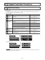
6. Digital Controller Functions ........................... 42
6-1 Alarm functions ...................................... 42
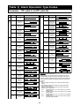
[Table 1] Alarm Operation Type Codes .............. 43
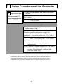
7. Setup Procedures of the Controller ............... 44
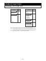
[Table 2] Input Codes ........................................ 46
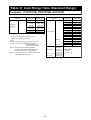
[Table 3] Input Range Table (Standard Range) . 47
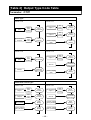
[Table 4] Output Type Code Table ...................... 48
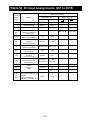
[Table 5] Di Input Assignments (Di1 to Di15) .... 50
[Table 6] Do and LED display Assignments ...... 51
[Table 7] Standby Operation .............................. 51
[Table 8] User Assignable Function keys .......... 52
[Table 9] Type of Math function .......................... 53
[Table 10] Control template ............................... 54
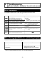
8. Troubleshooting
[Please read when the display does not make
sense] ...................................................... 55
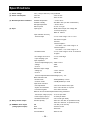
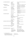
Model Specification ............................................ 56
PXH Model Code .......................................... 56
Specificaitons ................................................ 59
–1–
Confirming Specifications and Accessories
Before using the product, confirm that it matches the type ordered.
(For model code, please refer to pages 56 to 58.)
Confirm that all of the following accessories are included.
• Digital Controller ········ 1 unit
• Instruction Manual ····· 1 copy
• Mounting fixture ········· 2 pcs.
• Waterproof packing ···· 1 pc.
• Unit nameplate ··········· 1 pc.
• Terminating resistance∗1 ··········· 1 pc.
∗1) Supplied only when the communications function (RS485) is selected with this model.
Option
Name
Order No.
PC loader communication cable
ZZPPXH1∗TK4H4563
Terminal covers ∗2
ZZPPXR1-B230
∗2) Two pieces are required per unit.
Related Information
Refer to the following reference materials for details about the items described in this manual.
Content
Document
Specifications
Catalogue
User’s Manual (Basic control type)
Operation Method
User’s Manual (Motorized valve type)
User’s Manual (Heating/cooling type)
Communication Communication Functions Instruction Manual (Modbus) for
Functions
Digital Controller (type: PXH)
Parameter Loader Instruction Manual for
Loader Functions
Digital Controller (type: PXH)
The latest materials can also be downloaded at the following
URL: http://www.fujielectric.com/products/instruments/
–2–
Reference Number
ECNO: 1152
INP-TN514206-E
INP-TN514357-E
INP-TN514557-E
INP-TN514207-E
INP-TN514208-E
PLEASE READ FIRST
SAFETY WARNINGS
Please read the section “Safety Warnings” thoroughly before using.
Please observe the warnings stated here as they contain important safety details. The safety warning
items are divided into “WARNING” and “CAUTION” categories.
1.
Warning
Mishandling may lead to death or serious
injury.
Caution
Mishandling may cause injury to the user or
property damage.
WARNING
1.1 Limitations in Use
This product was developed, designed and manufactured on the premise that it would be used for general machinery.
In particular, if this product is to be used for applications that require the utmost safety as described
below, please take into consideration the safety of the entire system and the machine by adopting such
means as a fail-safe design, a redundancy design as well as the conducting of periodical inspections.
• Safety devices for the purpose of protecting the human body
• Direct control of transportation equipment
• Airplanes
• Space equipment
• Atomic equipment, etc
Please do not use this product for applications which directly concern human lives.
–3–
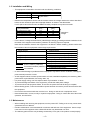
1.2 Installation and Wiring
•
This equipment is intended to be used under the following conditions.
Ambient temperature
Ambient humidity
Installation category
Pollution level
•
-10°C to 50°C
90% RH or below (with no condensation)
II
by IEC1010-1
2
Between the temperature sensor and the location where the voltage reaches the values described
below, secure clearance space and creepage distance as shown in the table below.
If such space cannot be secured, the EN61010 safety compliance may become invalid.
Voltage used or generated Clearance Space Creepage Space
[mm]
[mm]
by any assemblies
Up to 50 Vrms or Vdc
0.2
1.2
Up to 100 Vrms or Vdc
0.2
1.4
Up to 150 Vrms or Vdc
0.5
1.6
Up to 300 Vrms or Vdc
1.5
3.0
Please consult our distributor
Above 300 Vrms or Vdc
•
For the above, if voltage exceeds 50Vdc (called danger voltage), grounding and basic insulation for all
terminals of the equipment and auxiliary insulation for warning outputs is required.
Note that the insulation class for this equipment is as follows. Before installing, please confirm that
the insulation class for equipment meets usage requirements.
Power source
Digital output 1, 2
Digital output 3
Digital output 4
Digital output 11 to 15
Basic insulation (1500VAC)
Functional insulation (500VAC)
No insulation
•
•
•
•
•
•
•
•
hazardous
voltage
Internal Circuit
PC Loader interface
Measurement value input 1 (PV1)
Measurement value input 2 (PV2)
Auxiliary analog Input 1 (Ai1)
Output 1 (Current / SSR driver)
Output 2 (Current / SSR driver)
Digital input 1 to 4
Digital input 11 to 15
Transmitter power supply
RS485
In cases where damage or problems with this equipment may lead to serious accidents, install appropriate external protective circuits.
As this equipment does not have a power switch or fuses, install them separately as necessary. (Main
power switch: 2point Breaker, fuse rating: 250V 1A)
For power supply wiring, use wire equal to 600V vinyl insulation or above.
To prevent damage and failure of the equipment, provide the rated power voltage.
To prevent shock and equipment failure, do not turn the power ON until all wiring is complete.
Before feeding power, confirm that clearance space has been secured to prevent shock and fire with
the equipment.
Do not touch the terminal while the machine is on. Doing so risks shock or equipment errors.
Never disassemble, convert, modify or repair this equipment. Doing so carries the risk of abnormal
operation, shock and fire.
1.3 Maintenance
•
•
•
When installing and removing the equipment, turn the power OFF. Failing to do so may cause shock
operational errors or failures.
Periodic maintenance is recommended for continuous and safe use of this equipment. Some components used on this equipment have a limited life and/or may deteriorate over time.
The warranty period for this unit (including accessories) is one year, if the product is used properly.
–4–
2.
Caution
2.1 Cautions when Installing
Please avoid installing in the following locations.
• Locations in which the ambient temperature falls outside the range of –10 to 50°C when equipment is
in use. (If the power supply is AC200V, the recommended maximum ambient temperature is 45°C.)
• Locations in which the ambient humidity falls outside the range of 0 to 90% RH when equipment is in
use
• Locations with rapid temperature changes, leading to dew condensation
• Locations with corrosive gases (especially sulfide gas, ammonia, etc.) or flammable gases
• Locations in contact with water, oil, chemicals, steam or hot water
(If the equipment gets wet, there is a risk of electric shock or fire, so have it inspected by the distributor.)
• Locations with high concentrations of atmospheric dust, salt or iron particles
• Locations with large inductive interference, resulting in static electricity, magnetic fields or noise
• Locations in direct sunlight.
• Locations that build up heat from radiant heat sources, etc.
–5–
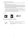
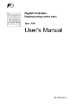
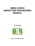
2.2 Cautions when Attaching the Panels
•
•
•
Please attach the PXH with the included Fixtures (2 pieces) to the top and bottom, and tighten with a
screwdriver.
The clamp torque is approximately 0.15 N·m (1.5 kg·cm)
(However, do exercise caution in not applying too much torque because the casing is made of plastic.)
The front of this equipment is wateproof in compliance with NEMA-4X standards (IP66-equivalent).
However, regarding waterproofing between the equipment and the panel, use the included packing to
ensure waterproofing and attach it according to the guidelines below. (Incorrect attachment may
cause the equipment to lose its waterproof capabilities.)
q As shown in Fig. 1, insert the panel after attaching the packing to the equipment case.
w As shown in Fig. 2, tighten the fixture screws so that no gaps can remain between the equipment
face, the packing and the panels. Once finished, confirm that there are no changes in shape such
as displaced or improperly-fitted packing, etc. as shown in Fig. 3.
Please exercise caution if the panel strength is weak and gaps develop between the packing and the
panel, as this will result in the loss of its waterproofing capabilities.
Mounting method
Fig. 2
Fig. 1
Unit
Mounting
fixture
Screw
Fig. 3
Packing
Packing
Case
Case
Packing
Front
Panel
Panel
Screw
Mounting fixture
(Bad)
(Good)
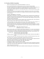
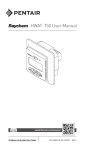
Standard: vertical panel attachment (horizontal position installing)
If attached at an angle, the maximum gradient is a 30° downslope.
α
=
0
to
30
°
Fig. 4
(Caution)
• In order not to hamper heat radiation, do not block the sides of the equipment.
• Do not block the air vents on the upper part of the terminal.
• For the PXH9, please attach the Fixtures to the attachment holes in the
center of the main unit.
–6–
2.3 Cautions for Wire Connections
•
•
•
•
•
•
•
•
•
•
•
•
•
•
•
Perform wiring beginning from the left-side terminals (No. 1 to No. 12).
Do not connect anyting to the unused terminals. (Do not use them as relay terminals.)
For thermocouple input use the appropriate compensating cable; for resistance bulb sensors, use
wires with small resistance and without any resistance difference among the three wires.
To avoid noise conductor effects, do not use input signal wires in close proximity with electric power
lines or load lines.
Use input signal lines and output signal lines that are separated from each other and are shielded.
If there is a lot of noise from the power source, adding an insulation transducer and using a noise filter
is recommended.
(Example: TDK ZMB22R5-11 noise filter)
Always attach a noise filter to a panel that is grounded securely, and keep the wiring between the
noise filter output side and the measuring equipment power terminal wiring to a minimum length.
Please do not attach fuses and switches, etc. to the noise filter output wiring since doing so will
decrease the filter’s effectiveness.
Twisting the measuring instrument wiring is effective when connecting the wires. (The shorter the
pitch of the twist, the more effective the connection is against noise.)
It takes preparation time before operation starts for the contact output when power is turned on. If
using it as a signal to an external interlock circuit, please couple it with a delayed relay.
Concerning the output relay, connecting the maximum rated load will shorten the relay’s life; so please
attach an auxiliary relay. If the output operation frequency is high, selecting a SSR/SSC drive output
type is recommended.
[Proportional cycles] Relay output: 30 seconds or more,
SSR/SSC drive output: 1 second or more
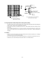
When inductive loads such as magnetic opening/closing equipment, etc. as relay output equipment
are connected, use of “Zetrap,” manufactured by Fuji Device Technology, Co. Ltd., is recommended in
order to protect the connection points against opening/closing surges and to ensure long-term use.
Model names : ENC241D-05A (For 100V power voltage)
ENC471D-05A (For 200V power voltage)
Attachment position : Please connect between the relay control output connection points. (Refer to
Fig. 5.)
If using a thermocouple input, make sure that an RCJ module is connected as shown in Fig 5. (If an
RCJ module is not connected, the temperature measurement cannot function.)
To use resistance bulb input instead of thermocouple input, remove RCJ module. Keep the removed
RCJ module, and do not forget to mount it back again when input is changed.
Take wiring resistance into consideration when using a Zener barrier.
In applying mV voltage, do not remove the RCJ module.
It is dangerous to make an SSR connection when the output is set at 4-20mA, because the output will
be kept “ON” even when the MV display shows –5%. Make sure to confirm the setting and the wiring
before making the SSR connection.
When the transmitter power supply model is selected, the external wiring will be connected as Fig. 6.
–7–
4 to 20mA DC
3
OUT2
+
4 –
Zetrap
Transmitter
Connected
externally.
PV1
+
33
36 –
Terminal
Transmitter
power supply
output
Input type code 26
(4 to 20mA DC)
Input impedance (250Ω)
Main unit
RCJ module
RCJ module (for PV2)
Fig. 6 External wiring for the model with
the transmitter power supply
Fig. 5 Attachement position of
Zetrap and RCJ module
2.4 Key Operation Cautions/Operations during Abnormality
•
•
•
The alarm function does not work properly when an abnormality takes place unless the settings are
made correctly. Always verify its setting before operation.
If the input wiring breaks, the display will read UUUU. When replacing the sensor, always turn the
power OFF.
The PV display will read UUUU or LLLL when over range or under range during input. However, if the
display limit is smaller than the over-range/under-range, the fixed number -19999 or 99999 will be
displayed.
2.5 Others
•
•
•
Please do not wipe the equipment with organic solvents such as alcohol or benzene, etc. If wiping is
necessary, do so with a neutral cleaning agent.
Do not use mobile phones near this instrument (within 50 cm). Otherwise a malfunction may occur.
Trouble may occur if the instrument is used near a radio, TV, or wireless device.
–8–
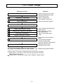
For Proper Usage
<Reference Item>
<Details>
Model Designation Confirmation
• Please confirm that the model
delivered matches your order
1
Installation / Mounting
2
Wire Connection
• External dimensions
• Panel cut dimensions
• How to install on the panel
• Terminal connection diagram
Turn Power On
3
Usage (Read before using)
4
Display and Operation Methods
5
Switching Parameters
6
Digital Controller Function
7
Controller Set-up Procedure
• How to change the temperature
setting values
• Basic method of operation
• List of parameters
• Table of input/output/alarm
codes
• Set up input sensor and input
range
• Control method selection
• Control via auto-tuning
Automatic settings of parameters
• Motorized valve control
• Heating/cooling control
Operation
8 When the display does not make sense.
• Displays during abnormalities.
Since about 15 minutes is needed until the unit becomes thermally
stable,wait for 15 minutes or more after turning the power on before
making measurements, etc.
It takes about 7 seconds from power ON to establish a stable output.
–9–
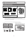
1
Installation/mounting
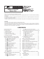
External/Panel Cut Dimensions
Outline Dimensions
Panel Cutout Dimensions
(Unit: mm)
Outline dimensions drawing (96mm type) (unit: mm)
92.0
+0.8
+0.8
0
92.0 0
116MIN.
96
91.5
107.5
96
79.5
2 Mounting fixture
6.2
10
Waterproof packing
t (1
t
Terminal
screw M3
8)
Panel
RCJ module
RCJ module (for PV2)
PC Loader interface
37-48 49-60 61-72
1-12
100MIN.
13-24 25-36
Note: In the case where a paint finish will be
applied after panel hole-punching, take
care of the finished dimensions.
• In case of using the packing in installation, please note the below procedure.
(The overtightening condition may occur and it makes the enclosure strained.)
♦ Turn the screw until the center of mounting fixture spilits into right and left and clanking soundsheard
approx. 5 times.
*The clamping torque will be fitted automatically in this condition.
*
*
•
Depending on the models, some terminals will remain unused (terminals 37 to 60). A terminal block
should not be installed onto these unused terminals. (A dummy cover will be installed.)
Use a PC loader interface when using the parameter loader. An optional PC loader communication
cable is required to use the parameter loader.
Use wires and Crimp-style terminals of the size shown below for connections.
Connection using terminal cover
Wire size
Parts
2
Size
Thermocouple
(Compensation wire)
1.25mm2 or smaller
Wire
1.25mm2 or smaller
• Connect 2 wires of 1.25mm or smaller in size
together to the same terminal as shown below.
Pass through
the top of the cover.
Crimp-style terminal
Compatible wire size
Fastening torque
0.8N·m
Pass
through
the bottom
of the cover
3.2mm
φ3.2mm
6.0mm or less
6.0mm or less
0.25 to 1.25mm2
– 10 –
Terminal cover
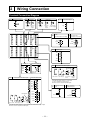
2
Wiring Connection
Terminal Connection Diagram
D03/Control output 2
DO3
Output 1
OUT1
+
1
5
+
1
2
6
-
2
4
-
49
1
13
25
38
50
2
14
26
39
51
3
15
27
40
52
4
16
28
17
5
+
3
-
SSR/SSC
driver
output
4
54
6
18
43
55
7
19
31
44
56
8
20
32
45
57
9
21
33
46
58
10
22
34
47
59
11
23
35
48
60
12
24
36
+
14
SG
15
-
16
-
Transmitter
power supply
DO4/
Motorized valve
DO4 Control output 1 (relay) PO opening/closing output
NC
COM
29
42
DO1, 2
4
-
Current
output
37
53
3
Communication
RS485
+
3
Current SSR/SSC
output
driver
output
41
Output 2
OUT2
+
NO
30
Di1-4
25
OPEN
25
26
COM
26
27
CLOSE
27
Digital input
DI1
28
DI2
29
DI3
30
DI4
31
COM
32
Power supply
PV1
FG
DOCOM
DO1
7
8
11
DO2
9
12
Measurement value input 1
10
+
+
33
33
+
34
100 to 240 V AC
50/60 Hz
PV2
+
Measurement value input
57
+
58
-
-
DI11
49
50
DI12
50
51
DI13
51
52
DI14
52
53
DI15
53
54
COM
54
60
DC voltage
AI1
18
55
DO12
56
-
57
DO13
57
DC voltage
58
DO14
58
59
DO15
59
COM
60
58
59
+
Thermocouple
Auxiliary analog
Valve opening
FB
input
feedback input
DO11
B
Resistance
bulb
The RCJ module must be connected
in case of thermocouple input.
Remove it for resistance bulb input.
RCJ Module 56
B
60
60
- 60
[V] [mV]
Resistance ThermoDC current DC voltage bulb
couple
60
DC current
55
A
-
49
- 36 - 36
[mV]
[V]
+
57
+
Extended-Di / Do
- 36
RCJ Module 33
+
B
34
34
A
35
35
B
36
- 36
The RCJ module must be connected in case of thermocouple input.
Remove it for resistance bulb input.
– 11 –
19
I + (100%)
Io
20
18
19
20
I - (0%)
Potentiometer
3
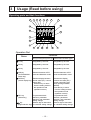
Usage (Read before using)
Operating parts and their functions
10
11 12 13
14
15
16
17
20
19
21
22
18
1
5
2
6
3
7
8
4
9
Operation Part
Name
Function
Basic type, Heating/cooling control type Motorized control type
q F1 key
Assignable by the user.
Assignable by the user.
w F2 key
Assignable by the user.
Assignable by the user.
e F3 key
Assignable by the user.
Assignable by the user.
r A/M key
(AUTO/MANUAL
switch key)
t DISP key
(switch display key)
Switches between AUTO
mode and MANUAL mode
Switches between AUTO
mode and MANUAL mode
Switches display between
the set value (SV) / control
output (MV).
Press the key to return
from the setting mode to
the operation mode
(operation screen).
Switches the display
between set value (SV) /
control output (MV) and
valve opening feedback
(MVRB).
Press the key to return
from the setting mode to
the operation mode
(operation screen).
For
parameter
block
For
parameter block
y SEL key
selection, parameter
selection, parameter
(Select key)
selection, and parameter
selection, and parameter
setting change.
setting change.
Select a digit of data value
Select a digit of data value
u key
(Digit selection key) for a desired setting change. for a desired setting change.
– 12 –
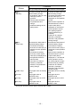
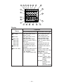
i
Name
i
key
(Up key)
o
key
(Down key)
!0 STBY Lamp
!1 R Lamp
!2 A Lamp
!3 M Lamp
Function
Basic type, Heating/cooling control type Motorized control type
Increases the data value of a Increases the data value of a
desired setting change.
desired setting change.
Increases the setting when
Changes the value of a set
the set value (SV) is
value (SV) when in
displayed on the operation
operation.
screen.
Used to select channels
Manual valve operation is
and parameters and
change
allowed when the control
parameter settings in the
output value (MV) is
setting mode.
displayed on the manual
mode operation screen.
(An opening signal is
output while the key is
pressed.)
Used also for channel
selection, parameter
selection, and parameter
setting change.
Decreases the data value of Decreases the data value of
a desired setting change.
a desired setting change.
・ Decreases the setting
・ Decreases the setting
when the set value (SV) is
when the set value (SV) is
displayed on the operation
displayed on the operation
screen.
screen.
・ Manual valve operation is
・ Decreases the setting
allowed when the control
when the control output
value (MV) is displayed on
output value (MV) is
displayed on the manual
the operation screen in
mode operation screen.
manual mode.
(A closing signal is output
Used also for channel
while the key is pressed.)
selection, parameter
Used also for channel
selection, and parameter
setting change.
selection, parameter
selection, and parameter
setting change.
Lamp lights when in standby Lamp lights when in standby
mode.
mode.
Lamp lights when in
Lamp lights when in
REMOTE mode.
REMOTE mode.
Lamp lights when in AUTO
Lamp lights when in AUTO
mode.
mode.
Lamp lights when in
Lamp lights when in
MANUAL mode.
MANUAL mode.
∗ During the electrical current output, the lamp will not light.
– 13 –
10
11 12 13
14
15
16
17
20
19
21
22
18
1
5
2
6
3
7
8
4
9
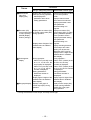
Display
Name
!4 C1 Lamp
!5 C2 Lamp
!6 DO1 Lamp
DO2 Lamp
DO3 Lamp
DO4 Lamp
DO5 Lamp
!7 ALM Lamp
!8 SV / MV Lamp
Function
Basic type, Heating/cooling control type Motorized control type
Lamp lights when control
output 1 is ON. ∗
Lamp lights when control
output 2 is ON. ∗
Lamp lights when digital
output 1 to output 4 (DO1 to
DO4) is on.
The lamp functions are
assignable by the user.
Lamp lights when alarm is
activated.
Indicates the status shown in
the sub-segment display.
SV : Set value
MV : Control output value
!9
– 14 –
Kept on while valve open
output (OPEN) is ON.
Kept on while valve close
output (CLOSE) is ON.
Lamp lights when digital
output 1 to output 4 (DO1 to
DO4) is on.
The lamp functions are
assignable by the user.
Lamp lights when alarm is
activated.
Display the type of data
appearing in the lower 5-digit
display section.
SV lights : Set value
MV lights : Control output
(MV)
MV lights + lights : Valve
opening feedback
(MVRB)
MV lights + blink :
Estimated valve
opening
(estimated MVRB)
Name
!9 Measurement
value (PV)
display (red)
Function
Basic type, Heating/cooling control type Motorized control type
Displays the measurement
value (PV) during operation.
Also displays the
parameter name when
setting parameters.
Displays the set values (SV)
@0 Set value (SV)
control output (MV) or control output value (MV)
or value opening during operation.
(MVRB) display
section (orange)
Displays lower 5 digits of the
totalized value in totalized
value display.
@1 Sub-segment
display
@2 Bar graph display
During operation :
When TPLT (ch8-92) is set
at 10, 13, 16, 50 or 53, the
loop number is displayed.
When TPLT (ch8-92) is set
at 11, 14, 51, 54, the SV
number is displayed.
Setting parameters :
Parameter number is
displayed.
Display higher 2 digits of the
totalized value in totalized
value display.
Displays a bar graph of
control output (MV) during
operation.
Displays measurement value
(PV) on the operation
screen.
Displays channel name
when channel is selected.
Displays parameter name
while parameter
selection/setting is in
progress.
Displays set values (SV),
control output (MV), or valve
opening feedback (MVRB)
on the operation screen.
Displays parameter setting
while parameter
selection/setting is in
progress.
Display switching between
control output and valve
opening can be set with
parameter dSPT (ch9-78).
Displays lower 5 digits of the
totalized value in totalized
value display.
During operation :
When TPLT (ch8-92) is set
at 30 or 33, the loop
number is displayed.
When TPLT (ch8-92) is set
at 31 or 34, the SV number
is displayed.
Setting parameters :
Parameter number is
displayed.
Display higher 2 digits of the
totalized value in totalized
value display.
Displays control output (MV)
or valve opening feedback
(MVRB) with a bar graph
during operation.
∗ During the electrical current output, the lamp will not light.
– 15 –
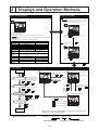
4
Displays and Operation Methods
When in Standby Operation
During Operation Mode
1 To change the setting values (SV)
• To Operate standby mode : set STbY (ch1 to 5) to ON.
Caution
STBY
If the key operation is not performed for 10 seconds
while the SV value is flickering, the value returns to
the previous setting value (SV).
Comes
on
A
Comes
on
STbY(ch1-5)=OFF
• Operation during standby mode:
No alarm will be activated.
Control output will be produced in accordance with the PMv1 (ch2 to 22) parameter.
Caution
Press the
key to enter the setting value
(SV) change mode.
Be aware that in standby mode, the unit’s warning alarm will not be activated
either.
(Display) STBY LED stays ON. (PV/SV display can be kept OFF.)
Operation output
Alarm output
Timer operation
Hold operation
Latch operation
Non-excitation
output operation
Communication
Analog
re-transmission
output
Digital output (Do)
Digital input(Di)
Control mode
Display
During standby
Return fromstandby
Outputs value designated by PMv1. Bumpless restart from PMv1.
All outputs are OFF.
–
All operations are OFF.
Zero start
–
Initial start
All operations are OFF.
Initial start (released)
All outputs are OFF.
Work in non-excitation
operation
(Non-exitation operations are invalid)
Not affected by standby status.
A / M key
2 To change the output
value (MV)
M
Comes
on
0mA
All outputs are OFF.
–
Status detection: Operated
Edge detection: Not operated.
Not affected by standby status.
Can be selected from ON/OFF
ON
–
Press the
key to enter the output value
(MV) change mode.
Switch by SEL key
Parameter Setting
Operation mode
(Operation display)
1 Channel selection display
2 Parameter selection display
Channel
No.
Select a desired channel
SEL
and press SEL or
Parameter name
.
Setting value
1
Channel selection display
Refer to the parameter
changing method for details.
Parameter
No.
Select a desired channel using the
or the
key, and then
press the SEL or the
2
Press DISP to return.
key.
Press SEL to
register
Parameter selection display
After selecting a desired
parameter, press SEL
Select a desired parameter using the
or the
key, and then
press the SEL or the
3
Press DISP to
return without
making
registration.
key.
.
3 Parameter change status
Parameter change
Press the
or
,
or the
key
to change the setting.
Press the SEL key to register the setting.
Press DISP for 2 seconds.
: Increases the set value.
Parameter selection display
: Decreases the set value.
Press DISP twice.
: Moves the cursor between digits.
Press DISP for 2 seconds.
Operation mode
(Operation display)
Parameter display in the text
Note that the display is not automatically returned from parameter setting
display, etc. to the operation display.
Example)
STbY (ch1-5)
Parameter symbol
– 16 –
Channel No.
Parameter No.
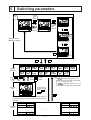
5
Switching parameters
Option
MV
SV
DISP
DISP
Totalized
value
switching
SV/MV
switching
PV/totalized value
DISP
Decimal
point
flickers
Operation mode
(Operation display)
Totalizer instantaneous
value/totalized value
DISP
DISP
PV/Math operation result
SEL
Channel
selection
DISP
Password 1
Ch1
Password 2
Ch2
Ch3
Ch4
Ch7
Ch8
ChA
ChB
ChC
ChD
ChE
ChF
ChG
ChX
Press SEL or
Press SEL to confirm
in
Press DISP to confirm
or
Ch9
Note:
Ch4
is displayed only when "F" is
specified for the 5th digit of the code symbols.
"A", "D", "S" displays only Ch3.
ChF
is displayed only when "D", "S" is
specified for the 5th digit of the code symbols.
After selecting a
desired channel,
press SEL or
Password
entry
.
DISP
If the value entered does not allow PS1=PAS1 (Ch9-1) or
PS2=PAS2 (Ch9-2) to hold, the later channels cannot be
selected.
Parameter No. Parameter name
Parameter
selection
Parameter No. Parameter name
01
01
37
90
– 17 –
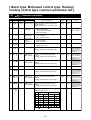
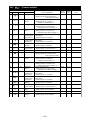
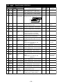
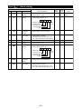
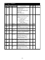
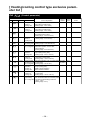
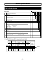
[ Basic type, Motorized control type, Heating/
cooling control type common parameter list ]
Ch1
(Operation parameter)
Parameter
No.
Content Explanation
Factory Parameter
default
mask
Symbol
Name
1
rEM1
Remote mode
Switches setting between remote/auto
mode operation.
REM: Remote mode AUT: Auto mode
AUT
01-1
5
STbY
Standby
command
Switches controller to RUN/Standby.
ON: Control standby
(output OFF, alarm OFF)
OFF: Control RUN
OFF
01-5
Display
Refer to Table 7.
7
AT
Auto-tuning
command
Sets auto-tuning.
OFF: non-action
ON1: start auto-tuning.
OFF
01-7
8
LACh
Alarm latch
clear
command
Disables alarm 1 - 8 latch.
OFF: non-action
CLR: Latch clear
OFF
01-8
9
PLTn
Palette selection Selects a PID palette to be used to control.
(Setting range: 0 to 7)
0
01-10
10
AL1
Alarm settings 1
Alarm 1 operation value setting.
Setting possible within the input range
10%FS
02-1
11
A1-L
Alarm lower
limit settings 1
Alarm 1 lower limit operation value
setting.
Setting possible within the input range
10%FS
02-1
12
A1-h
Alarm upper
limit settings 1
Alarm 1 upper limit operation value
setting.
Setting possible within the input range
10%FS
02-1
31
AL8
Alarm settings 8
Alarm 8 operation value setting.
Setting possible within the input range
10%FS
02-8
32
A8-L
Alarm lower
limit settings 8
Alarm 8 lower limit operation value
setting.
Setting possible within the input range
10%FS
02-8
33
A8-h
Alarm upper
limit settings 8
Alarm 8 upper limit operation value
setting.
Setting possible within the input range
10%FS
02-8
34
LoC
Keylock
Selects parameter lock type
(Setting range: 0 to 5)
0
01-11
Key operation
Communication
No. All Parm. SV/MV All Parm. SV/MV
0
1
2
3
4
5
: Can be set
– 18 –
: Cannot be set
Notes
Displayed when
alarm operation
type 1TP (chA-1)
is set to 1 to 11.
(See table 1.)
Displayed when
alarm operation
type 1TP (chA-1)
is set to 16 to 31.
(See table 1.)
Displayed when
alarm operation
type 1TP (chA-1)
is set to 16 to 31.
(See table 1.)
Displayed when
alarm operation
type 8TP (chA-36)
is set to 1 to 11.
(See table 1.)
Displayed when
alarm operation
type 8TP (chA-36)
is set to 16 to 31.
(See table 1.)
Displayed when
alarm operation
type 8TP (chA-36)
is set to 16 to 31.
(See table 1.)
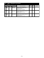
Ch1
(Operation parameter)
Parameter
No.
Content Explanation
Factory Parameter
default
mask
Symbol
Name
35
JP1
Parameter
jump setting 1
Press the function key (when 60 is
selected), and the display jumps to the
specified parameter.
(Setting range: I-01 to Z-Z9)
2-01
01-12
36
JP2
Parameter
jump setting 2
Press the function key (when 61 is
selected), and the display jumps to the
specified parameter.
(Setting range: I-01 to Z-Z9)
2-02
01-12
37
JP3
Parameter
jump setting 3
Press the function key (when 62 is
selected), and the display jumps to the
specified parameter.
(Setting range: I-01 to Z-Z9)
2-03
01-12
Display
– 19 –
Notes
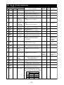
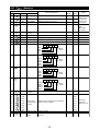
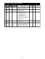
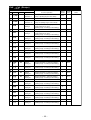
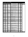
Ch2
(Control parameter)
Parameter
No.
Display
Symbol
Content Explanation
Name
1
P1
Proportional
band
Setting range: 0.0 to 999.9%
ON/OFF control at setting = 0.
2
i1
Integral time
3
d1
5
Factory Parameter
default
mask
Notes
5.0
03-1
Setting range: 0.0 to 3200.0 seconds
Integral control OFF at setting = 0.
240.0
03-1
Derivative time
Setting range: 0.0 to 999.9 seconds
Derivative control OFF at setting = 0.
60.0
03-1
Arh1
Anti - reset
windup
Upper limit
setting value
Integration cut point upper limit setting
value
(Setting range: 0 to 100%FS)
100%FS
03-3
Sets by deviation from SV.
6
ArL1
Anti - reset
windup
Lower limit
setting value
Integration cut point lower limit setting
value
(Setting range: 0 to 100%FS)
100%FS
03-3
Sets by deviation from SV.
7
Sh1
SV value
upper limit
Sets upper limit SV
(Setting range: -25 to 125%FS)
100%FS
03-4
8
SL1
SV value
lower limit
Sets lower limit SV
(Setting range: -25 to 125%FS)
0%FS
03-4
9
Mvh1
MV value
upper limit
Sets upper limit MV
(Setting range: -25.0 to 125.0%FS)
105.0
03-5
10
MvL1
MV value
lower limit
Sets lower limit MV
(Setting range: -25.0 to 125.0%FS)
-5.0
03-5
13
dMv1
MV change
ratio limit
Sets the limit value of deviation of MV
(DMV) in one control cycle (50ms.)
(Setting range: 0.0 to 150.0%)
0.0: No limit
0.0%
03-7
Limit is not
applied to the
deviation of MV
by EX-MV
operation.
14
dT1
Sampling cycle
Sets sampling cycle for PID operation.
(Setting range: 5 to 1000)
5
03-8
The actual
cycle is
(dT1 × 10) ms.
15
hS1
Hysteresis
setting
Hysteresis value during ON/OFF control
time. (Setting range: 0 to 50%FS)
0.3%FS
03-9
18
bAL1
Operation
output
convergence
value
Sets output convergence value
(Setting range: -100.0 to 100.0%)
0.0%
03-12
19
TC1
Cycle time of
Control output
(MV1)
Sets proportional cycle for control output.
(Setting range: 1 to 150 sec)
By
designation
at the time
of ordering
03-13
20
rEv1
Control
action
setting
Sets a control action method.
NRML: Normal (Direct) action
REV: Reverse action
REV
03-14
22
PMv1
Preset value for Sets MV for stanby mode.
control output
(Setting range: -25.0 to 125.0%)
0.0
03-16
23
ALP1
Alpha
Sets 2 degrees of freedom coefficient
α. (Setting range: -300.0 to 300.0%)
40.0
40-1
24
bET1
Beta
Sets 2 degrees of freedom coefficient
β. (Setting range: 0.0 to 999.9%)
100.0
40-1
38
Ld1
Output limiter
type setting
Sets whether the value should be limited
at the output limit setting or the limit
should be exceeded (125%, 25%) when
the output reaches the output limit setting.
3
40-9
LD1
0
1
2
3
Output operation
Upper side
Lower side
125.0%
125.0%
Limit
Limit
–25.0%
Limit
–25.0%
Limit
– 20 –
Effective only
for RY output
and SSR drive
output
Refer to Table 7.
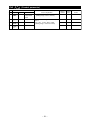
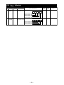
Ch2
(Control parameter)
Parameter
No.
Display
Symbol
Name
External
manipulated
value
FF gain
97
EXM1
99
kF1
A0
b1F1
FF bias1
A1
b2F1
FF bias2
Content Explanation
Factory Parameter
mask
default
Sets external output value.
(Setting range: -25.0 to 125.0%)
0.0
07-1
Sets Feed Forward gain and bias 1,
bias 2.
[FF = KF1 × (Input - B1F) + B2F]
(Setting range: -1000.0 to 1000.0)
0.0
40-2
0.0
40-2
0.0
40-2
– 21 –
Notes
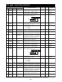
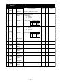
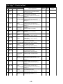
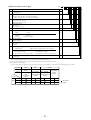
Ch3
(Control palette)
Parameter
No.
Display
Content Explanation
Symbol
Name
1
Sv1
Setting value 1
palette 1 SV
(Setting range: SV lower limit value
to SV upper limit value)
2
P-1
Proportional
band 1
palette 1 proportional band
(Setting range: 0.0 to 999.9%)
ON/OFF control at setting = 0.
3
i-1
Integral time 1
4
d-1
6
Factory Parameter
default
mask
0%FS
08-1
5.0
08-1
palette 1 integral time
(Setting range: 0.0 to 3200.0 sec)
Integral control OFF at setting = 0.
240.0
08-1
Derivative
time 1
palette 1 derivative time
(Setting range: 0.0 to 999.9 sec)
Derivative control OFF at setting = 0.
60.0
08-1
Arh1
Anti - reset
windup upper
limit value 1
palette 1 Anti - reset windup upper limit
value setting.
(Setting range: 0 to 100%FS)
100%FS
08-1
7
ArL1
Anti - reset
windup lower
limit value 1
palette 1 Anti - reset windup lower limit
value setting.
(Setting range: 0 to 100%FS)
100%FS
08-1
8
hYS1
Hysteresis
setting 1
palette 1 hysteresis setting
(Setting range: 0 to 50%FS)
0.3%FS
08-1
11
bL-1
Output convergence value 1
palette 1 Output convergence value
(Setting range: -100.0 to 100.0%)
0.0%
08-1
67
Sv7
Setting value 7
palette 7 SV
(Setting range: SV lower limit value
to SV upper limit value)
0%FS
14-1
68
P-7
Proportional
band 7
palette 7 proportional band
(Setting range: 0.0 to 999.9%)
ON/OFF control at setting = 0.
5.0
14-1
69
i-7
Integral time 7
palette 7 integral time
(Setting range: 0.0 to 3200.0 sec)
Integral control OFF at setting = 0.
240.0
14-1
70
d-7
Derivative
time 7
palette 7 derivative time
(Setting range: 0.0 to 999.9 sec)
Derivative control OFF at setting = 0.
60.0
14-1
72
Arh7
Anti - reset
windup upper
limit value 7
palette 7 Anti - reset windup upper limit
value setting.
(Setting range: 0 to 100%FS)
100%FS
14-1
73
ArL7
Anti - reset
windup lower
limit value 7
palette 7 Anti - reset windup lower limit
value setting.
(Setting range: 0 to 100%FS)
100%FS
14-1
74
hYS7
Hysteresis
setting 7
palette 7 hysteresis setting
(Setting range: 0 to 50%FS)
0.3%FS
14-1
77
bL-7
Output convergence value 7
palette 7 Output convergence value
(Setting range: -100.0 to 100.0%)
0.0%
14-1
78
rEF1
PID switch
point 1
palette 1 PID switch point
(Setting range: -25 to 125%FS)
0%FS
08-1
84
rEF7
PID switch
point 7
palette 7 PID switch point
(Setting range: -25 to 125%FS)
0%FS
14-1
– 22 –
Notes
Ch7
(Monitor)
Parameter
No.
Display
Symbol
Content Explanation
Name
Factory Parameter
default
mask
1
Pv1
PV1 monitor
Displays Process value 1 input.
–
17-1
2
Pv2
PV2 monitor
Displays Process value 2 input.
–
17-2
4
Ai1
AI1 monitor
Displays Analog input 1 input.
–
17-5
6
rSv1
RSV1 monitor
Displays remote set value 1.
–
17-9
10
LSV1
Local SV1
monitor
Display Local set value 1
–
17-9
14
RCJ1
RCJ1 monitor
Displays RCJ1 input.
–
17-1
15
RCJ2
RCJ2 monitor
Displays RCJ2 input.
–
17-2
17
Ao1
AO1 monitor
Displays Analog output 1 output value.
–
18-1
18
Ao2
AO2 monitor
Displays Analog output 2 output value.
–
18-1
21
Di01
DI monitor 1
Displays DI1 to 4 status.
–
19-1
–
19-1
–
19-1
–
19-1
–
19-3
DI4
DI3
DI2
DI1
22
Di11
DI monitor 2
DO01
DO monitor 1
Displays DI11 to 15 status.
DO11
DO monitor 2
Displays DO1 to 4 status.
OFF: Blank
ON : Do No.
Displays DO11 to 15 status.
DO15
DO14
DO13
DO12
DO11
Math result
monitor
OFF: Blank
ON : Do No.
27
AiM
28
TM1
34-1
29
TM2
34-2
30
TM3
34-3
31
TM4
32
TM5
33
TM6
34
TM7
Alarm delay
remaining time
monitor
Control RSV
value
(after input
correction)
OFF: Blank
ON : Di No.
DO4
DO3
DO2
DO1
25
Reading of the
signal input to
the terminal
(before input
correction)
OFF: Blank
ON : Di No.
DI15
DI14
DI13
DI12
DI11
24
Notes
Displays result of Math operation.
Displays the remaining time for the alarm
delay of ALM1 to ALM8.
–
34-4
34-5
34-6
34-7
35
TM8
36
AMV1
EXMV monitor
Displays EXMV.
–
17-9
40
FFV1
Feed Forward
value
Displays the value of Feed Forward
element.
–
17-9
34-8
– 23 –
The alarm
option will
select the unit.
Ch7
(Monitor)
Parameter
No.
100
Display
Symbol
DiC1
Name
Content Explanation
Communication Displays the status of communication Di1-5.
Di monitor (1-5)
Factory Parameter
default
mask
–
19-4
–
19-4
Communication Di5
Communication Di4
Communication Di3
Communication Di2
Communication Di1
101
DiC2
Communication Displays the status of communication Di6-8.
Di monitor (6-8)
Communication Di8
Communication Di7
Communication Di6
– 24 –
Notes
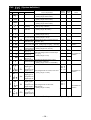
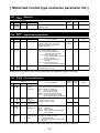
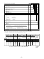
Ch8
(Input/output definition)
Parameter
No.
Display
Content Explanation
Symbol
Name
1
Pv1F
PV1 full-scale
2
Pv1b
PV1 base scale Sets the base-side scale of PV1 input.
(Setting range: -19999 to 99999)
3
Pv1d
PV1 decimal
point position
Sets the full-side scale of PV1 input.
(Setting range: -19999 to 99999)
Factory Parameter
mask
default
Notes
As ordered
20-1
For details see
Table 3.
As ordered
20-1
For details see
Table 3.
Specifies the decimal point position of PV1 As ordered
input. (Setting range: 0 to 3)
20-1
3:
2:
1:
0 : No decimal point
4
Pv1T
PV1 input type
Sets the type of PV1 input.
(Setting range: 0 to 27)
As ordered
20-1
5
Pv1U
Pv1 unit
Sets the measurement unit.
non : No unit
˚F : ˚F unit
˚C : ˚C unit
As ordered
20-2
6
Pv1Z
PV1 input zero
point adjustment
Sets the correction value of a zero point for
PV1 input. (Setting range: -50 to 50%FS)
0%FS
20-3
7
Pv1S
PV1 input span
point adjustment
Sets the correction value of a span point for
PV1 input. (Setting range: -50 to 50%FS)
0%FS
20-3
11
P1CU
PV1 input
cut point
Sets the cut point of square-root extraction
calculation for PV1 input. In case of OFF,
the square-root extraction is not calculated.
(Setting range: OFF, 0.0 to 125.0%)
OFF
20-7
12
P1TF
Pv1 input filter
Sets the time constant for PV1 input filter.
(Setting range: 0.0 to 900.0 sec)
0.0
20-8
13
P1Ln
PV1 linearize
setting
PV1 input linearize enable/disable setting
(Setting range: OFF, nrML, hi-C, Lo-C)
OFF
20-9
14
Pv2F
PV2 full-scale
Sets the full-side scale of PV2 input.
(Setting range: -19999 to 99999)
As ordered
20-1
For details see
Table 3.
15
Pv2b
PV2 base scale Sets the base-side scale of PV2 input.
(Setting range: -19999 to 99999)
As ordered
20-1
For details see
Table 3.
16
Pv2d
PV2 decimal
point position
1
20-1
Specifies the decimal point position of PV2
input. (Setting range: 0 to 3)
For details see
Table 2.
3:
2:
1:
0 : No decimal point
17
Pv2T
PV2 input type
Sets the type of PV2 input.
(Setting range: 0 to 27)
3
20-1
18
Pv2U
Pv2 unit
Sets the measurement unit for PV2 input.
non : No unit
˚F : ˚F unit
˚C : ˚C unit
˚C
20-2
19
Pv2Z
PV2 input zero
point adjustment
Sets the correction value of a zero point for
PV2 input. (Setting range: -50 to 50%FS)
0%FS
20-3
20
Pv2S
PV2 input span
point adjustment
Sets the correction value of a span point for
PV2 input. (Setting range: -50 to 50%FS)
0%FS
20-3
24
P2CU
PV2 input cut
point
Sets the cut point of square-root extraction
calculation for PV2 input. In case of OFF,
the square-root extraction is not calculated.
(Setting range: OFF, 0.0 to 125.0%)
OFF
20-7
25
P2TF
Pv2 input filter
Sets the time constant for PV2 input filter.
(Setting range: 0.0 to 900.0 sec)
0.0
20-8
26
P2Ln
PV2 linearize
setting
PV2 input linearize enable/disable setting
(Setting range: OFF, nrML, hi-C, Lo-C)
OFF
21-9
Note) Be sure to reset or turn on the power after the parameter setting is changed.
– 25 –
For details see
Table 2.
Ch8
(Input/output definition)
Parameter
No.
Display
Symbol
Name
Content Explanation
Factory Parameter
default
mask
40
Ai1F
Ai1 full scale
Sets the full-side scale of analog (Ai1)
input. (Setting range: -19999 to 99999)
As ordered
23-1
41
Ai1b
Ai1 base scale
Sets the scale of base-side analog (Ai1)
input. (Setting range: -19999 to 99999)
As ordered
23-1
42
Ai1d
Ai1 decimal
point position
Specifies the decimal point position for
analog (Ai1) input. (Setting range: 0 to 3)
1
23-1
16
23-1
Notes
3:
2:
1:
0 : No decimal point
43
Ai1T
Ai1 input type
Sets the type of Ai1 input.
(Setting range: 16 to 18)
45
Ai1Z
Ai1 input zero
point adjustment
Sets the correction value of a zero point for
Ai1 input. (Setting range: -50 to 50%FS)
0%FS
23-3
46
Ai1S
Ai1 input span
point adjustment
Sets the correction value of a span point for
Ai1 input. (Setting range: -50 to 50%FS)
0%FS
23-3
49
A1CU
Ai1 input cut
point
Sets the cut point of the square-root extraction
calculation for Ai1 input. In case of OFF, the
square-root extraction is not calculated.
(Setting range: OFF, 0.0 to 125.0%)
OFF
23-7
50
A1TF
Ai1 input filter
Sets the time constant for Ai1 input filter.
(Setting range: 0.0 to 900.0sec)
0.0
23-8
51
A1Ln
Ai1 linearize
setting
Ai1 input linearize enable/disable setting
(Setting range: OFF, nrML, hi-C. Lo-C)
OFF
23-9
64
Ao1T
AO1 output
type
Switches the AO1 (re-transmission output)
signal.
Setting range: PV, SV, MV, DV, AiM,
MVRB, TV
PV
25-1
66
Ao1h
AO1 output
scale upper limit
Sets the scale upper limit value of the AO1
output. (Setting range: -130.0 to 130.0%)
100.0%
25-1
67
Ao1L
AO1 output
scale lower limit
Sets the scale lower limit value of the AO1
output. (Setting range: -130.0 to 130.0%)
0.0%
25-1
68
A1Lh
AO1 output
limit upper limit
Sets the upper limt value of the AO1 output
limit. (Setting range: -25.0 to 105.0%)
105.0%
25-1
69
A1LL
AO1 output
limit lower limit
Sets the lower limt value of the AO1 output
limit. (Setting range: -25.0 to 105.0%)
-5.0%
25-1
70
Ao2T
AO2 output
type
Switches the AO2 (re-transmission output)
signal.
Setting range: PV, SV, MV, DV, AiM,
MVRB, TV
PV
25-2
72
Ao2h
AO2 output
scale upper limit
Sets the scale upper limit value of the AO2 100.0%
output. (Setting range: -130.0 to 130.0%)
25-2
73
Ao2L
AO2 output
scale lower limit
Sets the scale lower limit value of the AO2
output. (Setting range: -130.0 to 130.0%)
0.0%
25-2
74
A2Lh
AO2 output
limit upper limit
Sets the upper limt value of the AO2 output
limit. (Setting range: -25.0 to 105.0%)
105.0%
25-2
75
A2LL
AO2 output
limit lower limit
Sets the lower limt value of the AO2 output
limit. (Setting range: -25.0 to 105.0%)
-5.0%
25-2
88
CALC
Calculation
setting
Math function type setting.
(Setting range: 0 to 40)
0
25-9
89
UCF1
Math function
full scale
Sets the scale on the full side which is
utilized for mathematical calculations.
(Setting range: -19999 to 99999)
As ordered
25-9
Note) Be sure to reset or turn on the power after the parameter setting is changed.
– 26 –
For details see
Table 2.
It is invalid when
the control output
is chosen.
It is invalid
when the XPS
is attached.
For details see
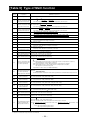
Table 9.
Ch8
(Input/output definition)
Parameter
No.
Display
Symbol
Name
Content Explanation
90
UCb1
Math function
base scale
Sets the scale on the base side which is
utilized for mathematical calculations.
(Setting range: -19999 to 99999)
91
UCd1
Math function
decimal point
position
92
TPLT
93
Factory Parameter
mask
default
As ordered
25-9
Sets the decimal point position for
mathematical calculations.
(Setting range: 0 to 3)
1
25-9
Template
Specifies the template.
The range of effective setting.
10 : Single-loop basic PID control
(with Math function)
11 : Single-loop SV selection PID control
(with Math function)
13 : Single-loop basic PID control
14 : Single-loop SV selection PID control
16 : Single-loop input selection PID
control
(with Math function)
Setup other than the above is forbidden.
13
25-10
oTYP
Output type
Selects the control output selector type.
(Setting range: 10 to 13)
98
CN01
System
constant 1
b3
CN16
System
constant 16
Sets a constant value used for templates.
The meaning of the value varies depending
on template. Make the setting after
checking the description of each template.
(Setting range: -19999 to 99999)
As ordered 25-11
0
25-15
Note) Be sure to reset or turn on the power after the parameter setting is changed.
– 27 –
Notes
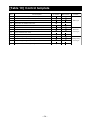
For details see
Table 4.
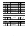
Ch9
(System definition)
Parameter
No.
Display
Symbol
Name
Content Explanation
Factory Parameter
mask
default
1
PAS1
Password 1
Sets security (passwords).
(Setting range: 0000 to FFFF)
0000
26-1
2
PAS2
Password 2
Sets security (password).
(Setting range: 0000 to FFFF)
0000
26-2
3
PAS3
Password 3
Sets security (password).
(Setting range: 0000 to FFFF)
0000
26-3
7
rih1
Remote mode
inhibiting
Prevents switching to the REMOTE mode.
(Setting range: ON/OFF)
OFF
27-1
11
rAC1
R_ACK use
selection
Selects use or non-use of R_ACK.
(Setting range: INH, ENA)
INH
27-5
15
A-M1
A/M mode
Selects the A/M mode.
(Setting range: A-M, A)
A-M
27-9
19
Cnd1
Mode settings when Sets the mode when the power turns ON.
the power turns ON. (Setting range: A, R, M)
A
28-1
23
Trk1
Tracking method
selection (SV)
ON
28-9
30
STBo
Operation settings Sets the front display operation in the standby
when in standby mode mode. (Setting range: 0: lighting, 1: extinction)
0
29-4
31
PLTS
palette switching Selects a palette switching factor.
(Setting range: PLTn, SV, PV)
method selection
PLTn
29-6
32
F1
User designation
key-1 (F1)
0
29-7
33
F2
User designation
key-2 (F2)
0
29-8
34
F3
User designation
key-3 (F3)
0
29-9
35
brd1
Burnout direction
specification (MV1)
Lo
30-1
39
di01
Assignment for
digital input 1
31-1
42
di04
Assignment for
digital input 4
di01 : 60
di02 : 70
di03 : 0
di04 : 103
43
di11
Assignment for
digital input 11
47
di15
Assignment for
digital input 15
53
do1
Assignment for
digital output 1
56
do4
Assignment for
digital output 4
57
do11
Assignment for
digital output 11
61
do15
Assignment for
digital output 15
Selects ON or OFF for tracking the local
set value (SV)
Sets user assignments for function keys.
[F1] - [F3].
(Setting range: 0 to 27)
Specifies the direction of the control
output during a burnout.
(Setting range: HOLD, LO, UP, EXMV)
Sets assignments for DI1-DI4, DI11-DI15.
(Setting range: 0 to 255)
Sets assignments for DO1-DO4,
DO11-DO15.
(Setting range: 0 to 255)
0
31-2
do1 : 1
do2 : 2
do3 : 3
do4 : 4
31-9
0
31-10
Note) Be sure to reset or turn on the power after the parameter setting is changed.
– 28 –
Notes
For details see
Table 7.
For details see
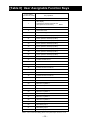
Table 8.
For details see
Table 5.
For details see
Table 6.
Ch9
(System definition)
Parameter
No.
Display
Symbol
Name
Content Explanation
Factory Parameter
default
mask
67
C1
LED C1
assignment
21
32-1
68
C2
LED C2
assignment
22
32-2
69
Ldo1
LED DO1
assignment
73
Ldo5
Ldo1 : 1
Ldo2 : 2
Ldo3 : 3
Ldo4 : 4
Ldo5 : 0
32-3
32-4
32-5
32-6
32-7
74
LALM
LED ALM
assignment
17
32-8
79
odSP
Operation
display setting
000
32-15
Allocates indicator LEDs.
(Setting range: 0 to 255)
LED DO5
assignment
Sets display items during operation.
(Setting range: 000 to 111)
PV totalized value
Totalizer
instantaneous value
/totalized value
PV/Math calculation
result
80
dS00
C3
dS43
E3
rES
Parameter
mask setting
Skips (not display) unnecessary
parameters.
Reset
command
Resets the main unit.
ON : Reset
OFF : RUN
0-1
–
0-15
OFF
33-1
Note) Be sure to reset or turn on the power after the parameter setting is changed.
– 29 –
Notes
For details see
Table 6.
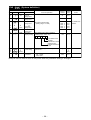
ChA
(Alarm setting)
Parameter
No.
Display
Symbol
Name
Factory Parameter
default
mask
Content Explanation
1
1TP
Alarm 1 type
setting
Sets the alarm type for alarm 1.
(Setting range: 0 to 38)
0
34-1
2
1oP
Alarm 1 option
setting
Sets alarm options for alarm 1.
(Setting range: 0000 to 1111)
0000
34-1
0.3%FS
34-1
Switching unit time
0: seconds 1:minutes
non-excitation output
Unit abnormal
Latch
0 : OFF
1 : ON
3
1hYS
Alarm 1
hysteresis
setting
Sets alarm hysteresis for alarm 1.
(Setting range: 0.00 to 50.00%FS)
4
1dLY
Alarm 1 delay
time setting
Sets delay time for alarm 1.
(Setting range: 0 to 9999)
∗ Sets alarm options for time units. The
unit of time is selected by alarm options.
0
34-1
36
8TP
Alarm 8 type
setting
Sets the alarm type for alarm 8.
(Setting range: 0 to 38)
0
34-8
37
8oP
Alarm 8 option
setting
Sets alarm options for alarm 8.
(Setting range: 0000 to 1111)
0000
34-8
0.3%FS
34-8
0
34-8
Switching time unit
0: seconds 1:minutes
non-excitation output
Abnormal input
Latch
0 : OFF
1 : ON
38
8hYS
Alarm 8
hysteresis
setting
Sets alarm hysteresis for alarm 8.
(Setting range: 0.00 to 50.00%FS)
39
8dLY
Alarm 8 delay
time setting
Sets delay time for alarm 8.
(Setting range: 0 to 9999)
∗ Sets alarm options for time units. The
unit of time is selected by alarm options.
– 30 –
Notes
For details see
Table 1.
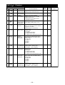
ChB
(Communication)
Parameter
No.
Display
Symbol
Name
Factory Parameter
default
mask
Content Explanation
2
STn4
RS485
station No.
Specifies the RS485 communication
station No. (Setting range: 0 to 255)
∗ does not operate with STn4=0.
1
36-2
3
SPd4
RS485
communication
speed
Selects the communication speed for
RS485 communication.
(Setting range)
96 : 9600 bps
192 : 19200 bps
384 : 38400 bps
384
36-3
4
biT4
RS485
bit format
Selects the bit format for RS485 communication.
(Setting range)
Data length Parity
8o
36-4
8n
8o
8E
8
8
8
None
Odd
Even
7
SPd2
PC Loader
communication
speed
Selects the communication speed for PC
Loader communication. (Setting range)
96 : 9600 bps
192 : 19200 bps
384 : 38400 bps
384
36-9
8
biT2
PC Loader
bit format
Selects the bit format for PC Loader
communication.
Data length Parity
(Setting range)
8n
8
None
8o
8
Odd
8E
8
Even
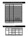
8o
36-10
51
Ci01
Communication Sets the function of communication Di1.
Di1 function
setting
0
36-16
52
Ci02
Communication Sets the function of communication Di2.
Di2 function
setting
0
36-16
53
Ci03
Communication Sets the function of communication Di3.
Di3 function
setting
0
36-16
54
Ci04
Communication Sets the function of communication Di4.
Di4 function
setting
0
36-16
55
Ci05
Communication Sets the function of communication Di5.
Di5 function
setting
0
36-16
56
Ci06
Communication Sets the function of communication Di6.
Di6 function
setting
0
36-16
57
Ci07
Communication Sets the function of communication Di7.
Di7 function
setting
0
36-16
58
Ci08
Communication Sets the function of communication Di8.
Di8 function
setting
0
36-16
Note) Be sure to reset or turn on the power after the parameter setting is changed.
– 31 –
Notes
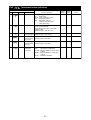
ChC
(Linearize)
Parameter
No.
Display
Content Explanation
Factory Parameter
default
mask
Symbol
Name
1
P1X0
Linearize table
P1X0
Linearize table X0 for PV1 input
(Setting range: –25% to 125%FS)
–25%FS
37-1
32
P1YF
Linearize table
P1YF
Linearize table YF for PV1 input
(Setting range: –25% to 125%FS)
125%FS
37-1
33
P2X0
Linearize table
P2X0
Linearize table X0 for PV2 input
(Setting range: –25% to 125%FS)
–25%FS
37-2
64
P2YF
Linearize table
P2YF
Linearize table YF for PV2 input
(Setting range: –25% to 125%FS)
125%FS
37-2
97
A1X0
Linearize table
A1X0
Linearize table X0 for Ai1 input
(Setting range: –25% to 125%FS)
–25%FS
37-4
128
A1YF
Linearize table
A1YF
Linearize table YF for Ai1 input
(Setting range: –25% to 125%FS)
125%FS
37-4
Notes
See 5-26.
Note) Be sure to reset or turn on the power after the parameter setting is changed.
ChD
(Mathematical Calculation)
Parameter
No.
Display
1
Symbol
k01
16
Name
Constant for
Math function
Content Explanation
Sets the constant used for mathematical
expressions.
Display
Notes
Floating-point
setting
38-4
(Tuning)
Parameter
1
38-1
0.0000
k16
ChE
No.
Factory Parameter
default
mask
Symbol
ATP1
Name
Auto tuning
type
Content Explanation
Specifies the auto-tuning method.
(Setting range)
NRML : Standard type AT
LPV : Low PV type AT
– 32 –
Factory Parameter
mask
default
NRML
39-1
Notes
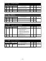
ChG
(Totalizer)
Parameter
No.
Display
Symbol
Name
Content Explanation
1
TrUn
Totalizer
Starts/stops/latches totalizer.
command/status (Setting range: HoLd/rUn/LATcH)
2
TrES
Totalizer
reset command
3
Toin
4
TdP
5
Factory Parameter
default
mask
HOLD
45-1
Resets totalizer value. (on/oFF)
oFF
45-1
Totalizer
input selection
Selects input used for totalizer.
(Setting range: Pv1, Pv2, Ai1, AiM)
* Math function scale
(Ch8-89, 90, 91) is adopted when
"(3) AiM" is selected.
Pv1
45-2
Totalized value
display decimal
point position
Sets decimal point position of totalized
value display. (Setting range: 0 to 4)
0
45-3
TCUT
Totalizer
cut point
Sets totalizer cut point for totalizer
input. The input lower than the totalizer
cut point is not added.
(Setting range: 0% to 100%FS)
0%FS
45-4
6
A1TP
Totalizer
alarm 1 type
Sets alarm type of totalizer alarm 1.
Setting range:
0: No alarm
1: Integrated value alarm
2: Totalizer batch output
3: Totalizer batch output (with auto reset)
0
45-5
7
A1on
Totalizer
alarm 1 ON
pulse width
Sets ON pulse width for batch control
batch output alarm for totalizer alarm 1.
Setting range:
0: Continuous
1: 100ms
2: 200ms
3: 500ms
4: 1 sec.
8
A1oP
Totalizer alarm
Sets excitation/non-excitation output for
1 excitation/non- totalizer alarm 1 (Setting range:
excitation setting 0: Excitation, 1; Non-excitation)
0
45-3
9
A2TP
Totalizer
alarm 2 type
Sets alarm type of totalizer alarm 2.
Setting range:
0: No alarm
1: Totalized value alarm
2: Totalizer batch output
3: Totalizer batch output (with auto reset)
0
45-6
10
A2on
Totalizer
alarm 2 ON
pulse width
Sets ON pulse width for totalized value
batch output alarm for totalizer alarm 2.
Setting range:
0: Continuous
1: 100ms
2: 200ms
3: 500ms
4: 1 sec.
0
45-6
11
A2oP
Totalizer alarm
Sets excitation/non-excitation output of
2 excitation/non- totalizer alarm 2. (Setting range:
excitation setting 0; Excitation, 1; Non-excitation)
0
45-6
– 33 –
45-5
Notes
ChG
(Totalizer)
Parameter
No.
Display
Symbol
Name
Content Explanation
Factory Parameter
default
mask
12
TMod
Operation mode Selects operation mode from Japanese
and European modes.
[Japanese mode] Calculation is made
using totalize factor.
[European mode] Calculation is made
based on totalizer reference time and
totalizer divisor.
Setting range:
(0) JPn: Japanese mode
(1) EnG: European mode
45-7
13
ToPT
Totalizer
option setting
0bit: Sets flickering of the totalized value
at the occurrence of totalized value over.
(Totalizer is suspended while the display
flickers.)
1bit: Totalizer operation at standby
0: Continue, 1: Stop
2bit: Command at power ON
0: Stop, 1: Start
3bit: Totalizer operation at the occurrence
of erroneous input
0: Add, 1: Not add
(bit setting: 0000 to 1111)
45-8
14
Tb
Totalizer
reference time
Sets reference unit time for totalizer.
(Setting range: SEC, Min, hour, dAY)
15
SCL
Totalizer
divisor
16
MUL
17
hoUr
45-9
Divisor for totalized value scale
conversion
Note: Addition is not performed when 0 is
selected. (Setting range: 0 to 1000000)
10000
45-9
Totalizer
multiplier
Multiplier for totalized value scale
conversion (Setting range 0 to 1000000)
1
45-9
TCF
Totalizer
factor
Totalized value display when 100% input
is continued for 1 hour (Setting range: 20
to 9999999. The decimal point appears
according to TdP setting.)
10000
45-10
18
TinT
Totalizer
initial value
The following relation holds when the
value different from the current setting is
selected as the initial value of totalizer.
Totalized value = Initial value of
totalizer (Setting range: 1999999 to
9999999. The decimal point appears
according to TdP setting.)
0
45-11
19
A1SP
Totalizer
alarm 1 setting
Sets the operation value of totalizer
alarm 1. (Setting range: 1999999 to
9999999. The decimal point appears
according to TdP setting.)
10000
45-5
20
A2SP
Totalizer
alarm 2 setting
Sets the operation value of totalizer
alarm 2. (Setting range: 1999999 to
9999999. The decimal point appears
according to TdP setting.)
10000
45-6
21
rTSc
Re-transmission Sets the totalized value that allows
re-transmission output to be 100%.
output source
(Setting range:1999999 to 9999999.
scale
The decimal point appears according to
TdP setting.)
10000
45-12
– 34 –
Notes
ChX
(Recipe)
Parameter
No.
Display
Symbol
Name
Content Explanation
Factory Parameter
default
mask
1
rCP0
Recipe
allocation 1
Sets parameter to be allocated as
recipe 1 (Setting range 0-00 to W-Z9)
0-00
46-1
10
rCP9
Recipe
allocation 10
Sets parameter to be allocated as
recipe 10 (Setting range: 0-00 to W-Z9)
0-00
46-10
11
d00
Recipe
setting 0
Recipe parameter 1 setting for palette 0
(when palette is not used)
(Setting range: According to rCP0 setting)
0
46-15
20
d09
Recipe
setting 9
Recipe parameter 10 setting for palette 0
(when palette is not used)
(Setting range: According to rCP9 setting)
0
46-15
21
d10
Recipe
setting 10
Recipe parameter 1 setting for palette 1
(Setting range: According to rCP0 setting)
0
46-1
30
d19
Recipe
setting 19
Recipe parameter 10 setting for palette 1
(Setting range: According to rCP9 setting)
0
46-10
31
d20
Recipe
setting 20
Recipe parameter 1 setting for palette 2
(Setting range: According to rCP0 setting)
0
46-1
40
d29
Recipe
setting 29
Recipe parameter 10 setting for palette 2
(Setting range: According to rCP9 setting)
0
46-10
41
d30
Recipe
setting 30
Recipe parameter 1 setting for palette 3
(Setting range: According to rCP0 setting)
0
46-1
50
d39
Recipe
setting 39
Recipe parameter 10 setting for palette 3
(Setting range: According to rCP9 setting)
0
46-10
51
d40
Recipe
setting 40
Recipe parameter 1 setting for palette 4
(Setting range: According to rCP0 setting)
0
46-1
60
d49
Recipe
setting 49
Recipe parameter 10 setting for palette 4
(Setting range: According to rCP9 setting)
0
46-10
61
d50
Recipe
setting 50
Recipe parameter 1 setting for palette 5
(Setting range: According to rCP0 setting)
0
46-1
70
d59
Recipe
setting 59
Recipe parameter 10 setting for palette 5
(Setting range: According to rCP9 setting)
0
46-10
71
d60
Recipe
setting 60
Recipe parameter 1 setting for palette 6
(Setting range: According to rCP0 setting)
0
46-1
80
d69
Recipe
setting 69
Recipe parameter 10 setting for palette 6
(Setting range: According to rCP9 setting)
0
46-10
81
d70
Recipe
setting 70
Recipe parameter 1 setting for palette 7
(Setting range: According to rCP0 setting)
0
46-1
90
d79
Recipe
setting 79
Recipe parameter 10 setting for palette 7
(Setting range: According to rCP9 setting)
0
46-10
– 35 –
Notes
[ Motorized control type exclusive parameter list ]
Ch7
(Monitor)
Parameter
No.
Display
50
Ch8
Symbol
Name
MVrb
Valve monitor
Content Explanation
Displays the valve opening degree
feedback value.
Display
–
Notes
17-5
(Input/output definition)
Parameter
No.
Factory Parameter
default
mask
Symbol
Content Explanation
Name
43
Ai1T
Ai1 input type
Sets the type of Ai1 input.
(Setting range: 16 to 18, 23, 24)
Sets 23 or 24 when used as valve
opening fead back.
92
TPLT
Template
Specifies the template.
The range of effective setting.
30 : 1-loop motor-operated valve
controller (with input Math)
31 : 1-loop SV selection type
motor-operated valve controller
(with input Math)
33 : 1-loop motor-operated valve
controller
34 : 1-loop SV selection type
motor-operated valve controller
93
oTYP
Output type
Selects the control output selector type.
(Setting range: 30 to 31)
Factory Parameter
mask
default
As
ordered
23-1
33
25-10
As ordered
25-11
Notes
Note) Be sure to reset or turn on the power after the parameter setting is changed.
Ch9
(System definition)
Parameter
No.
Display
Symbol
Name
35
brd1
Designates
output
at burnout
67
C1
LED C1
assignment
Content Explanation
Designates control output at input error or
valve opening degree feedback anomaly.
HOLD : Outputs to follow MV
Lo
: Turns on CLOSE signal
UP
: Turns on OPEN signal
EXMV: Controls to join EXMV setting
Poff : Turns off OPEN, and CLOSE
signals, allowing MV to join MVRB.
Allocates indicator LEDs.
(Setting range: 0 to 255)
68
C2
LED C2
assignment
76
brG1
Bar graph
display type
Select value to display on bar graph.
MON : No display
MV
: Control output
MVRB : Valve opening degree feedback
value (MVRB)
78
dSPT
Operation
screen display
type
Select value to indicate at 5-digit display
on bottom of operation screen.
0 : Control output (MV)
1 : Valve opening degree feedback value
(MVRB)
Factory Parameter
default
mask
Lo
30-1
19
32-1
20
32-2
MV
32-10
0
32-14
Note) Be sure to reset or turn on the power after the parameter setting is changed.
– 36 –
Notes
ChF
(motorized valve definition)
Parameter
No.
Display
Content Explanation
Symbol
Name
1
VTYP
Valve type
Sets control type of motorized valve.
Fb
: PFB control
Fb-Sr : PFB + estimation control
Sr1 : Estimation control 1
Sr2 : Estimation control 2
(Turning on power closes
valve all the way)
2
TrVL
Travel time
3
PGP
6
Factory Parameter
default
mask
Fb
44-1
Sets time required for valve
to move over full stroke.
Automatically set in case of automatic
adjust of valve.
(Setting range: 5.0 to 300.0 sec)
30.0S
44-2
Dead band of
valve operation
Sets dead band of OPEN/CLOSE signals.
(Setting range: 0.5 to 100.0%)
10.0%
44-3
AdPC
Calibration value
at which valve is
fully closed
Value at which valve is closed all the way.
(Setting range: 0 to FFFFF)
-
44-6
7
AdPO
Calibration value
at which valve is
fully open
Value at which valve is open all the way.
(Setting range: 0 to FFFFF)
-
44-7
8
CALb
Valve
calibration
command
Allows to adjust the valve.
OFF
: Termination of calibration
CLOSE : Manual calibration of fully closed
position
OPEN : Manual calibration of fully open
position
AUTO : Automatic calibration
OFF
44-8
– 37 –
Notes
[ Heating/cooling control type exclusive parameter list ]
Ch2
(Control parameter)
Parameter
No.
Display
Content Explanation
Factory Parameter
default
mask
Symbol
Name
11
hh1
MV upper limit
value on
heating side
Sets the upper limit value of operation
output (MV). (Heating side)
(Setting range: -25 to 125%)
100.0
40-8
12
Lh1
MV lower limit
value on
cooling side
Sets the lower limit value of operation
output (MV). (Heating side)
(Setting range: -25 to 125%)
0.0
40-8
17
db1
Dead band
Sets the dead band and overlap band
for heating/cooling control.
(Setting range: -100.0 to 50.0%)
0.0
03-11
25
PC1
Proportional
band on
cooling side
Sets the proportional band (cooling side).
(Setting range: 0.0 to 999.9%)
5.0
40-3
26
iC1
Integral time
on cooling side
Sets the integral time (cooling side).
(Setting range: 0.0 to 3200.00 sec)
240.0
40-3
27
dC1
Derivative time
on cooling side
Sets the derivative time (cooling side).
Derivative operation is set to OFF
when setting=0.
(Setting range: 0.0 to 999.9 sec)
60.0
40-3
28
hC1
MV upper limit
value on
cooling side
Sets the upper limit value of operation
output (MV) (cooling side).
(Setting range: -25.0 to 125.0%)
100.0
03-6
29
LC1
MV lower limit
value on
cooling side
Sets the lower limit value of operation
output (MV) (cooling side).
(Setting range: -25.0 to 125.0%)
0.0
03-6
34
TCC1
Control output
Sets the proportion cycle of control output 30.0 (RY)
proportion cycle (cooling side)
2.0 (SSR-d)
on cooling side (Setting range: 1 to 150 sec)
40-4
35
rVC1
Control
actuation
system on
cooling side
Sets the automatic system of control
output (cooling side).
NRML: Normal actuation
REV: Reverse actuation
NRML
40-5
37
PMC1
Control output
volume on
cooling side
Sets the output value at control standby
(cooling side)
(Setting range: -25.0 to 125.0%)
0.0
40-7
39
LdC1
Output limiter
type setting
on cooling side
Sets whether the output value on cooling
side should be limited or exceeded (scale
off) when the limit setting is reached
(125%, -25%)
(Setting range: 0 to 3)
3
03-6
– 38 –
Notes
Ch4
(Control palette)
Parameter
No.
Display
Content Explanation
Symbol
Name
1
Sv1
Setting value 1
Palette 1 SV
(Setting range: SV lower limit value
to SV upper limit value)
2
P-1
Proportional
band 1
Palette 1 proportional band
(Setting range: 0.0 to 999.9%)
ON/OFF control at setting = 0.
3
i-1
Integral time 1
4
d-1
6
Factory Parameter
default
mask
0%FS
08-1
5.0
08-1
Palette 1 integral time
(Setting range: 0.0 to 3200.0 sec)
Integral control OFF at setting = 0.
240.0
08-1
Derivative
time 1
Palette 1 derivative time
(Setting range: 0.0 to 999.9 sec)
Derivative control OFF at setting = 0.
60.0
08-1
Arh1
Anti - reset
windup upper
limit value 1
Palette 1 Anti - reset windup upper limit
value setting.
(Setting range: 0 to 100%FS)
100%FS
08-1
7
ArL1
Anti - reset
windup lower
limit value 1
Palette 1 Anti - reset windup lower limit
value setting.
(Setting range: 0 to 100%FS)
100%FS
08-1
10
Mh-1
MV upper limit
value 1
Palette 1 upper limit value of operation
output (MV).
(Setting range: -25.0 to 125.0%)
105.0
08-1
11
ML-1
MV lower limit
value 1
Palette 1 lower limit value of operation
output (MV).
(Setting range: -25.0 to 125.0%)
-5.0
08-1
12
hh-1
MV upper limit
value 1 on
heating side
Palette 1 upper limit value on heating side
of operation output (MV).
(Setting range: -25.0 to 125.0%)
100.0
08-1
13
Lh-1
MV lower limit
value 1 on
heating side
Palette 1 lower limit value on heating side
of operation output (MV).
(Setting range: -25.0 to 125.0%)
0.0
08-1
16
hYS1
Hysteresis 1
Palette 1 hysteresis.
(Setting range: 0 to 50%)
0.3%FS
08-1
18
db-1
Dead band 1
Palette 1 dead band and overlap band for
heating/cooling control.
(Setting range: -100.0 to 50%)
0.0
08-1
19
bL-1
Output
convergence
value 1
Palette 1 output convergence value.
(Setting range: -100.0 to 100%)
0.0
08-1
26
PC-1
Proportional
band 1 on
cooling side
Palette 1 proportional band on cooling side.
(Setting range: 0.0 to 999.9%)
Two-position operation is allowed when
setting = 0.
5.0
08-1
27
IC-1
Integral time 1
on cooling side
Palette 1 integral time on cooling side.
(Setting range: 0.0 to 3200.0 sec)
The integral operation is set to OFF when
setting = 0.
240.0
08-1
28
dC-1
Derivative
time 1
on cooling side
Palette 1 derivative time on heating side.
(Setting range: 0.0 to 999.9 sec)
The derivative operation is set to OFF
when setting = 0.
60.0
08-1
29
HC-1
MV upper limit
value 1
on cooling side
Palette 1 upper limit value on cooling side
of operation output (MV).
(Setting range: -25.0 to 125.0%)
100.0
08-1
30
LC-1
MV lower limit
value 1
on cooling side
Palette 1 lower limit value on cooling side
of operation output (MV).
(Setting range: -25.0 to 125.0%)
0.0
08-1
– 39 –
Notes
Ch4
(Control palette)
Parameter
No.
Display
Content Explanation
Symbol
Name
o1
Sv7
Setting value 7
Palette 7 SV.
(Setting range: SV lower limit value to
SV upper limit value)
o2
P-7
Proportional
band 7
on heating side
o3
i-7
o4
Factory Parameter
default
mask
0%FS
14-1
Palette 7 proportional band on heating side.
(Setting range: 0.0 to 999.9%)
Two-position operation is allowed when
setting = 0.
5.0
14-1
Integral time 7
on heating side
Palette 7 integral time on heating side.
(Setting range: 0.0 to 3200.0 sec.)
The integral operation is set to OFF when
setting = 0.
240.0
14-1
d-7
Derivative
time 7
on heating side
Palette 7 derivative time on heating side.
(Setting range: 0.0 to 999.9 sec.)
Derivative operation is set to OFF when
setting = 0.
60.0
14-1
o6
Arh7
Integration cut
point upper
limit value 7
Palette 7 upper limit value of integration
cut point.
(Setting range: 0 to 100%FS)
100%FS
14-1
o7
ArL7
ntegration cut
Palette 7 lower limit value of integration
point lower limit cut point.
value 7
(Setting range: 0 to 100%FS)
100%FS
14-1
P0
Mh-7
MV upper limit
value 7
Palette 7 upper limit value of operation
output (MV).
(Setting range: -25.0 to 125.0%)
105.0
14-1
P1
ML-7
MV lower limit
value 7
Palette 7 lower limit value of operation
output (MV).
(Setting range: -25.0 to 125.0%)
-5.0
14-1
P2
hh-7
MV upper limit
value 7
on heating side
Palette 7 upper limit value on heating side
of operation output (MV).
(Setting range: -25.0 to 125.0%)
100.0
14-1
P3
Lh-7
MV lower limit
value 7
on heating side
Palette 7 lower limit value on heating side
of operation output (MV).
(Setting range: -25.0 to 125.0%)
0.0
14-1
P6
hYS7
Hysteresis 7
Palette 7 hysteresis.
(Setting range: 0 to 50%FS)
0.3%FS
14-1
P8
db-7
Dead band 7
Palette 7 dead band and overlap band
for heating/cooling control.
(Setting range: -100.0 to 50.0%)
0.0
14-1
P9
BL-7
Output
convergence
value 7
Palette 7 output convergence value.
(Setting range: -100.0 to 100.0%)
0.0
14-1
q6
PC-7
Proportional
band 7
on cooling side
Palette 7 proportional band on cooling side.
(Setting range: 0.0 to 999.9%)
Two-position operation is allowed when
setting = 0.
5.0
14-1
q7
IC-7
Integral time 7
on cooling side
Palette 7 proportional band on cooling side.
(Setting range: 0.0 to 3200.0 sec)
Integral operation is set to OFF when
setting = 0.
240.0
14-1
q8
dC-7
Derivative
time 7
on cooling side
Palette 7 derivative time on cooling side.
(Setting range: 0.0 to 999.9 sec.)
Derivative operation is set to OFF when
setting = 0.
60.0
14-1
q9
HC-7
MV upper limit
value 7
on cooling side
Palette 7 upper limit value on cooling side
of operation output (MV).
(Setting range: -25.0 to 125.0%)
100.0
14-1
r0
LC-7
MV lower limit
value 7
on cooling side
Palette 7 lower limit value on cooling side
of operation output (MV).
(Setting range: -25.0 to 125.0%)
0.0
14-1
– 40 –
Notes
Ch4
(Control palette)
Parameter
No.
Display
Symbol
Content Explanation
Name
Factory Parameter
default
mask
T1
rEF1
PID switch
point 1
Palette 1 PID switch point
(Setting range: -25 to 125%FS)
0%FS
08-1
T7
rEF7
PID switch
point 7
Palette 7 PID switch point
(Setting range: -25 to 125%FS)
0%FS
14-1
Ch7
Display
Symbol
Content Explanation
Name
Factory Parameter
default
mask
44
HMV1
MV on
heating side
MV monitor on heating
–
18-3
48
CMV1
MV on
cooling side
MV monitor on cooling
–
18-3
Ch8
Display
Notes
(Input/output definition)
Parameter
No.
See 5-6.
(Monitor)
Parameter
No.
Notes
Symbol
Content Explanation
Name
Factory Parameter
mask
default
92
TPLT
Template
Specifies control template.
The range of effective setting.
50 : Single-loop heating/cooling control
(with math function)
51 : Single-loop SV selection heating/
cooling control (with math function)
53 : Single-loop heating/cooling control
54 : Single-loop SV selection heating/
cooling control
53
25-10
93
oTYP
Output type
Selects the control output selector type.
(Setting range: 50 to 55)
As ordered
25-11
Notes
Note) Be sure to reset or turn on the power after the parameter setting is changed.
Ch9
(System definition)
Parameter
No.
68
Display
Symbol
C2
Name
LED C2
assignment
Content Explanation
Allocates indicator LEDs.
(Setting range: 0 to 255)
Factory Parameter
default
mask
25
(Cooling
output)
32-2
Note) Be sure to reset or turn on the power after the parameter setting is changed.
– 41 –
Notes
6
Digital Controller Functions
6-1 Alarm functions
1) Alarm Types
• The alarm types are an absolute value alarm, a deviation alarm, an upper/lower limit alarm and a range alarm.
(For details see [Table 1 Alarm Operation Type Codes])
2) Alarm function
No. Function Name
1
Hysteresis
function
Function
Parameter set
Alarm operation can be set for operation dead band
(hysteresis).
alarm 1: 1hYS (chA-3)
alarm 8: 8hYS (chA-38)
2
ON delay
function
After alarm ON conditions are established, the alarm is
ON after the ON delay setting time.
alarm 1: 1dLY (chA-4)
alarm 8: 8dLY (chA-39)
3
Alarm latch
function
Alarm goes ON once, and alarm ON function status is
alarm 1: 1oP (chA-2)
maintained.
To release the alarm latch, the following methods are used. alarm 8: 8oP (chA-37)
I) Turns power ON again on the controller.
II) Turns alarm latch settings OFF once.
III) Releases latch on the alarm latch release screen.
LACH (ch1-8)
IV) Executes release with DI input.
di01 (ch9-39) to di04 (ch9-42)
V) Executes release with communication.
4
5
Abnormal
alarm
function
Sets alarm relay to ON when abnormality occurs in
equipment.
(For unit abnormalities, see the page on “Troubleshooting”.)
alarm 1: 1oP (chA-2)
De-energizing
function
Transmits to the alarm relay by excitation/non-excitation
of an alarm output.
(When function is ON, output will be by non-excitation.)
alarm 1: 1oP (chA-2)
alarm 8: 8oP (chA-37)
alarm 8: 8oP (chA-37)
ON delay function
Alarm operation
Normal alarm relay operation
ON delay time relay operation
ON
OFF
ON
OFF
ON
OFF
ON delay setting time
De-energizing function
Alarm determination
With De-energizing function OFF
With De-energizing function ON
ON
OFF
ON
OFF
ON
OFF
Caution When the power is off, even when the non-excitation function is ON, there will be no output during
standby. (Function will be OFF.)
– 42 –
[Table 1] Alarm Operation Type Codes
Parameter: 1TP (chA-1) to 8TP (chA-36)
1TP to 8TP
Absolute
value
Alarm
0
No alarm
1
Upper limit
absolute
2
3
Deviation
Alarm
Alarm Type
Operation Diagram
PV
Lower limit
absolute
(with hold)
5
Upper limit
deviation
PV
ALn
Alarm Type
24
Range
upper/lower limit
absolute
Range upper
limit/lower limit
deviation
An-L
25
Range upper
limit absolute
Lower limit
deviation
An-L
27
PV
ALn
1TP to 8TP
26
PV
ALn
Upper limit
absolute
(with hold)
4
PV
ALn
Lower limit
absolute
Range
Alarm
Range
Alarm
PV
7
ALn
Upper/lower limit
deviation
An-L
30
SV
8
9
10
Range
Alarm
11
Upper limit
deviation
(with hold)
Limit
ALn
32
PV
Upper/lower limit
deviation
(with hold)
Range upper/lower
limit deviation
Rate of
change
ALn
16
Upper/lower limit
absolute
35
PV
SV
ALn
PV
36
SV
Upper/lower limit
deviation
PV
SV
SV
Range upper
limit deviation
Lower limit
absolute(with hold)
PV
An-H
An-H
PV
An-H
An-H
An-L
SV upper/lower
limit
PV
SV
An-L
SV
SV
PV rate of
0%
ALn
100
change
Upper/lower limit PV change ratio among 5 cycles of
input sampling
ON delay
timer
DI
OUT
dLYn
ALn
ALn
PV
37
OFF delay
timer
DI
OUT
dLYn
An-L
An-H
PV
38
17
An-H
Timer
ALn
SV
Upper/
lower
limit
Alarm
An-L
SV
Lower limit
deviation
(with hold)
PV
PV
SV
Range upper
limit absolute
Lower limit
deviation (with hold)
31
PV
An-L
An-L
ALn
An-H
An-H
Range upper
limit/lower limit
deviation
(with hold)
SV
PV
SV
Range upper
limit deviation
Lower limit
absolute
PV
An-H
SV
29
ALn
Lower limit
deviation
An-H
Range upper
limit/lower limit
absolute
(with hold)
SV
6
An-L
28
ALn
PV
Operation Diagram
An-L
An-H
ON/OFF
delay timer
DI
OUT
dLYn
PV
dLYn
SV
18
Upper limit
absolute
Lower limit
deviation
19
Lower limit
absolute
Upper limit
deviation
An-L
SV
An-H
An-L
20
Upper/lower limit
absolute
(with hold)
21
Upper/lower limit
deviation
(with hold)
An-L
Upper limit absolute
Lower limit deviation
(with hold)
An-L
22
23
Upper limit deviation
Lower limit absolute
(with hold)
An-H
PV
PV
SV
An-L
An-H
PV
An-H
PV
SV
SV
An-H
PV
An-H
An-L
PV
SV
Caution The Hold Function:
This is an alarm for situations when the alarm does not turn
ON immediately, and the value go to outside the range once
and then reenters within the range, even when the measured
value is within the range of the alarm at the time the power is
turned on.
Notes)
• After changing the alarm type, confirm the alarm setting
values.
Alarm setting values may change by changing the alarm
type, but this is normal.
• Caution : The alarm latch function cannot be used when
using the OFF delay timer.
• ALn
: Indicates the AL1 (ch1-10) to AL8 (ch1-31) alarm
setting values.
• An-H : Indicates the A1-H (ch1-12) to A8-H (ch1-33) alarm
setting values.
• An-L : Indicates the A1-L (ch1-11) to A8-L (ch1-32) alarm
setting values.
• dLYn : Indicates the 1dLY (chA-4) to 8dLY (chA-39) alarm
ON delay setting values.
– 43 –
7
Setup Procedures of the Controller
1 Input settings
∗ Not necessary if
input was specified
when ordered.
q Does the input sensor type match the sensor
in use?
Select the sensor in use from Table 2 and set to
PV1T (ch8-4).
(Example) Set Pv1T (ch8-4) to “7” in the case of a
T thermocouple.
w Are the input range settings in the appropriate range
for the sensor in use?
The standard ranges for each sensor are shown in Table 2.
Select the appropriate temperature range for the
equipment in use and set the upper and lower limit values.
Lower limit / Pv1b (ch8-2), Upper limit / Pv1F (ch8-1).
(Example) If the temperature range is 0 to 800 [°C]:
Set 0 / Pv1b (ch8-2), 800 / Pv1F (ch8-1)
(Note) While it is possible to set outside the standard
range, the standard range settings are
recommended.
(Note) There are no standard ranges for DC Volt (and DC
Current) input. Set the upper and lower limits as
you wish. (within the range -19999 to 99999,
lower limit < upper limit)
Note 1) Set input sensor type PV1T (ch8-4) and input range settings (Pv1b (ch8-2), Pv1F (ch8-1), and
Pv1U (ch8-5)) in advance of all the other settings, and then reset the instrument without fail.
Other parameters may change when these parameters are changed, but this is normal.
Confirm all parameter values. Be sure to reset the instrument after setting the input range.
Otherwise improper values may be displayed. Be sure to check the setting after the reset.
– 44 –
2 Control Settings
∗ Please read if
controls are not
responding as you
expect.
q What is the control purpose? (To heat? To cool?)
Objective
To heat
To cool
Operation
Method
Explanation
Method
Reverse Raising the
measurement value
operation will reduce operation
output.
Set rEv1 (ch2-20)
Raising the measurement value will inoperation crease operation output.
Set rEv1 (ch2-20)
to REV.
Direct
to NRML.
w What kind of control is it? (PID, ON/OFF)
Control Type
Explanation
PID control
The output signal
changes within the
range of 0 to 100%
according to PID
calculation.
A stable control without
a control offset can be
achieved.
ON/OFF control Output is either ON
(2-position control) (100%) or OFF (0%).
(Suitable when
frequent output
switching is
inconvenient.)
– 45 –
Method
Please execute auto-tuning
manually.
The optimal P.I.D will be
calculated automatically.
(The PID value may also be
set manually.)
Set ch2 P1 (ch2-1) to “0.0”.
[Table 2] Input Codes
Parameter: PV1T, PV2T, AI1T
Input Type
Code
Input Type
Resistance bulb
• Pt100Ω (IEC)
•N
• PL-II
• WRe5-26
1
12
13
14
DC voltage
Thermocouple
•J
•K
•R
•B
•S
•T
•E
• PR40/20
Code
• 1 to 5V DC
• 0 to 5V DC
• 0 to 10V DC
• 0 to 10mV DC
• 0 to 50mV DC
2
3
4
5
6
7
8
9
16
17
18
19
20
DC current
• 4 to 20mA DC
• 0 to 20mA DC
26
27
Potentiometer
• Valve opening feedback
(with moving average filter)
• Valve opening feedback
23
24
Note 1) For PV1, and PV2, the potentiometer code ("23", "24") can not be selected.
Note 2) • If with PFB (PILC 5th digit = D), Ai1 can be set to potentiometer code "23", "24") only.
• If without PFB (PILC 5th digit = S), Ai1 can be set to DC current code "16", "18") only.
Note 3) If, on account of noise, ect., the valve opening degree feedback input suffers from an
abrupt change, select Ai1T = 23 (with moving average filter).
– 46 –
[Table 3] Input Range Table (Standard Range)
Parameter: PV1F/PV1B, PV2F/PV2B, AI1F/AI1B
Input Type
Pt100Ω
Resistance
bulb (RTD)
IEC
Measurement
Range (°C)
Measurement
Range (°F)
0 to 150
0 to 300
0 to 500
0 to 600
-50 to 100
-100 to 200
-150 to 600
-150 to 850
32 to 302
32 to 572
32 to 932
32 to 1112
-58 to 212
-148 to 392
-238 to 1112
-238 to 1562
• To use the Zener barrier for RTD input, user
adjustment (section 5-9) is required.
Note 1)
R thermocouple 0 to 500°C
B thermocouple 0 to 400°C
Proper values may not
be displayed within
these ranges due to the
sensor’s characteristics.
Input Type
J
J
K
K
K
R
B
Thermocouple S
T
T
E
E
PR40/20
N
PL-II
WRe5-26
Note 3) In the -50%FS to +50%FS display, values under
-199.99 will not be displayed.
0
0
0
0
0
0
0
0
-200
-200
0
-200
0
0
0
0
to 400
to 1000
to 400
to 800
to 1200
to 1600
to 1800
to 1600
to 200
to 400
to 800
to 800
to 1800
to 1300
to 1300
to 2300
DC voltage
1 to 5V DC
0 to 5V DC
0 to 10V DC -19999 to 99999
0 to 10mV DC
Scaling is
0 to 50mV DC
possible
DC current
4 to 20mA DC
0 to 20mA DC
Note 2) When using at the setting below the
minimum range stated in the table above,
the input accuracy is not guaranteed.
Measurement
Range (°C)
– 47 –
Measurement
Range (°F)
32
32
32
32
32
32
32
32
-328
-328
32
-328
32
32
32
32
to 752
to 1832
to 752
to 1472
to 2192
to 2912
to 3272
to 2912
to 392
to 752
to 1472
to 1472
to 3272
to 2372
to 2372
to 4172
[Table 4] Output Type Code Table
Parameter: OTYP
Basic type
OTYP = 10
Control output
(MV)
Re-transmission
output 2
OTYP = 11
Ao1
Limit
scaling
Ao2
Limit
scaling
OUT1
(Current/SSR drive)
OUT2
(Current)
Ao1
Limit
scaling
OUT1
(Current)
Re-transmission
output 2
Ao2
Limit
scaling
OUT2
(Current)
Do4
(Relay)
Control output
(MV)
OTYP = 12
Control output
(MV)
Re-transmission
output 1
OTYP = 13
Ao1
Limit
scaling
OUT1
(Current/SSR drive)
OUT2 [XPS]
(Transmitter
power supply)
24V DC
Re-transmission
output 1
Ao1
Limit
scaling
OUT1
(Current)
24V DC
OUT2 [XPS]
(Transmitter
power supply)
Control output
(MV)
Do4
(Relay)
Motorized control type
OTYP = 30
OTYP = 31
Re-transmission
output 1
Ao1
Limit
scaling
OUT1
(Current)
Re-transmission
output 1
Re-transmission
output 2
Ao2
Limit
scaling
OUT2
(Current)
24V DC
OUT2 [XPS]
(Transmitter
power supply)
Control output
(MV) (OPEN)
Open
(Relay)
Control output
(MV) (OPEN)
Open
(Relay)
Control output
(MV) (CLOSE)
Close
(Relay)
Control output
(MV) (CLOSE)
Close
(Relay)
– 48 –
Ao1
Limit
scaling
OUT1
(Current)
Heating / cooling control type
OTYP = 50
Control output
(MV) on heating side
Control output
(MV) on cooling side
OTYP = 51
Ao1
Limit
scaling
OUT1
(Current/SSR drive)
Ao2
Limit
scaling
OUT2
(Current/SSR drive)
OTYP = 52
Re-transmission
output 1
Re-transmission
output 1
Ao1
Limit
scaling
OUT1
(Current)
Re-transmission
output 2
Ao2
Limit
scaling
OUT2
(Current)
Control output
(MV) on cooling side
Do3
(Relay)
Control output
(MV) on heating side
Do4
(Relay)
OTYP = 53
Ao1
Limit
scaling
OUT1
(Current/SSR drive)
OUT2 [XPS]
(Transmitter
power supply)
24V DC
Re-transmission
output 1
Ao1
Limit
scaling
OUT1
(Current/SSR drive)
Control output
(MV) on cooling side
Ao2
Limit
scaling
OUT2
(Current/SSR drive)
Do3
(Relay)
Control output
(MV) on cooling side
Do4
(Relay)
Control output
(MV) on heating side
Do4
(Relay)
Control output
(MV) on heating side
OTYP = 55
OTYP = 54
Control output
(MV) on heating side
Ao1
Limit
scaling
OUT1
(Current/SSR drive)
Control output
(MV) on heating side
Re-transmission
output 2
Ao2
Limit
scaling
OUT2
(Current/SSR drive)
24V DC
OUT2 [XPS]
(Transmitter
power supply)
Do4
(Relay)
Control output
(MV) on cooling side
Do3
(Relay)
Control output
(MV) on cooling side
– 49 –
Ao1
Limit
scaling
OUT1
(Current/SSR drive)
[Table 5] Di Input Assignments (Di1 to Di15)
Operating Conditions
Di1 to Di15
Setting
Value
Function
0
Status detection
Edge detection
ON
OFF
None
–
–
–
–
1
STBY (standby)
Standby
RUN
–
–
30
AT (Auto tuning)
–
–
AT start
AT stop
40
Alarm latch reset
(Alarm1) to (Alarm 8)
Release all
–
–
Release all
Latch hold
50 to 57
Timer operating
(Alarm1) to (Alarm 8)
ON
OFF
–
–
60
R-ACK
(Remote
acknowledgement)
Remote
Local
–
–
70
SMV
(Manual command)
Manual mode
Auto mode
–
–
80
PV-TRK command
(PV tracking)
ON
OFF
–
–
EX-MV
MV
–
–
Hi selector
expression
Lo selector
expression
–
–
103
140
160
161
162
200
to
249
EX-MV
(External
control amount)
Switching of the
active expression for
Math function
Totalizer
start/stop,
reset
HOLD
Run
–
–
LATCH
Run
–
–
Reset
–
–
–
Binary data setting to
constant parameter CN01
to CN05
1st digit : Bit position
10th digit : Parameter No.
1
(1bit)
0
(1bit)
–
–
– 50 –
[Table 6] DO and LED display Assignments
DO output
LED display
DO01 to DO04
DO11 to DO15
C1, C2
LDO1 to LDO5
Type
0
0
No setting
1
1
ALM1
2
2
ALM2
3
3
ALM3
4
4
ALM4
5
5
ALM5
6
6
ALM6
7
7
ALM7
8
8
ALM8
17
17
OR of ALMs
–
21
Output (MV) 1
*3)
*3)
–
22
Output (MV) 2
29
29
System fault
41
41
Totalizer ALM1
42
42
Totalizer ALM2
80
80
Manual MV (status)
81
81
EX-MV command (status)
82
82
Remote SV (status)
83
83
Local SV (status)
84
84
PV tracking (status)
85
85
Normal (Direct) action (status)
86
86
Auto tuning (AT) (status)
87
87
Remote request (status)
88
88
Remote acknowledge (R-ACK) (Status)
89
89
Not-Auto (status)
90
90
Mode OR output 1
*1)
91
91
Mode OR output 2
*2)
*1) Contents of OR operation: Manual + Auto
*2) Contents of OR operation: Manual + EX-MV
*3) The lamp does not come ON for current (4 to 20mA) output type.
[Table 7] Standby operation
STBY
STBO
setting value setting value
ON
OFF
Operation during standby
MV output
Output other
than MV
Screen display
0
Value of PMv1
Value of PMC1 OFF or -25%
(-25% to 125%)
Lighting
1
Value of PMv1
Value of PMC1 OFF or -25%
(-25% to 125%)
Extinction
Normal
– 51 –
Normal
Lighting
[Table 8] User Assignable Function Keys
F key setting
(Function key code)
Key operation
0
No function
1
dSV display
Changeover between Remote and
Auto (Press for 2 seconds.)
Note 1
2
Standby/RUN changeover
3
Alarm latch reset
10
AT (Auto tuning) START/STOP
20
Timer operation start/stop (ALM 1)
21
Timer operation start/stop (ALM 2)
22
Timer operation start/stop (ALM 3)
23
Timer operation start/stop (ALM 4)
24
Timer operation start/stop (ALM 5)
25
Timer operation start/stop (ALM 6)
26
Timer operation start/stop (ALM 7)
27
Timer operation start/stop (ALM 8)
30
Totalizer RUN/HOLD
31
Totalizer RUN/LATCH
32
Totalizer RESET
41
Transfer of SV1 to local SV
42
Transfer of SV2 to local SV
43
Transfer of SV3 to local SV
44
Transfer of SV4 to local SV
45
Transfer of SV5 to local SV
46
Transfer of SV6 to local SV
47
Transfer of SV7 to local SV
50
Selection of palette 0
51
Selection of palette 1
52
Selection of palette 2
53
Selection of palette 3
54
Selection of palette 4
55
Selection of palette 5
56
Selection of palette 6
57
Selection of palette 7
60
Parameter jump 1
61
Parameter jump 2
62
Parameter jump 3
Note 1: Do not use this setting when TPLT (Ch8-92) is set to 11 or 14.
– 52 –
[Table 9] Type of Math function
CALC
setting
Name
of operation
0
No math operation
1
2
Arithmetic expression
M1 = PV1 input
*2
*1
Mathematical expression 1
Ai1 + k02
k04
X
M1 = k01 X
PV1 X
(Flow rate compensation with
k03
PV2 + k05
temperature and pressure)
PV1: Flow rate (differential pressure), PV2: Temperature, Ai1: Pressure
*1
Mathematical expression 2
k04
Ai1 + k02
M1 = k01 X PV1 X
X
(Flow rate compensation with
PV2 + k05
k03
temperature and pressure)
PV1: Flow rate (differential pressure), PV2: Temperature, Ai1: Pressure
3
k04
Mathematical expression 3 M1 = k01 x PV1 x Ai1+k02 x
k03
PV2+k05
(Flow rate compensation with
temperature and pressure)
PV1: Flow rate (differential pressure), PV2: Temperature, Ai1: Pressure
4
Mathematical expression 4 M1 =
(k01 X (k02 X PV1 + k03 X PV2 + k04 X Ai1) + k05)
(k06 X (k07 X PV1 + k08 X PV2 + k09 X Ai1) + k10)
5
Mathematical expression 5 M1 =
(k01 X ((k02 X PV1 + k03) X (k04 X PV2 + k05) X (k06 X Ai1 + k07)) + k08)
(k09 X ((k10 X PV1 + k11) X (k12 X PV2 + k13) X (k14 X Ai1 + k15)) + k16)
6
Mathematical expression 6 M1 = k01 X PV1 X (k02 X PV2 + k03 X Ai1) + k04 X Ai1 + k05
M1 = Max (PV1, PV2)
H selector (2 points)
PV1 or PV2, whichever is larger, is selected.
M1 = Min (PV1, PV2)
L selector (2 points)
PV1 or PV2, whichever is smaller, is selected.
M1 = Max (PV1, PV2, Ai1)
H selector (3 points)
PV1, PV2, or Ai1, whichever is largest, is selected.
7
8
9
10
L selector (3 points)
11
Input switching (2 points)
M1 = Min (PV1, PV2, Ai1)
PV1, PV2, or Ai1, whichever is smallest, is selected.
M1 = PV1 when PV1
k01, M1 = PV2 when PV1 > k01
12
Expression 7 or 8 is used by Di switching.
H/L selector (2 points)
(with Di switching function) (Specify ”140” for Di function for switching.)
13
Expression 9 or 10 is used by Di switching.
H/L selector (3 points)
(with Di switching function) (Specify ”140” for Di function for switching.)
M1 =
20
21
PV1
(Ai1 + k01) + k02
(PV2 X k03) + k04
PV1: Differential pressure (flow rate) % value, k01: Pressure compensation constant 1,
k04: Temperature compensation constant 2
PV2: Fluid temperature % value, k03: Temperature compensation constant 1
Ai1: Differential pressure % value, k02: Pressure compensation constant 2,
k05: Square-root extractor cut point
*Input data: % value (0 (0%) to 100000 (100.000%))
Flow rate compensation with
temperature and pressure
[% value operation]
Flow rate compensation with
(Ai1 X k01) + k02
temperature and pressure M1 =PV1
(PV2 X k03) + k04
[% value operation]
All the inputs and constants are of the same specifications as mathematical expression 20.
(without square-root extraction)
27
H selector (2 points)
(with coefficient)
M1 = max ((PV1 X k01 + k02), (PV2 X k03 + k04))
28
L selector (2 points)
(with coefficient)
M1 = min ((PV1 X k01 + k02), (PV2 X k03 + k04))
29
H selector (3 points)
(with coefficient)
M1 = max ((PV1 X k01 + k02), (PV2 X k03 + k04), (Ai X k05 + k06))
30
L selector (3 points)
(with coefficient)
M1 = min ((PV1 X k01 + k02), (PV2 X k03 + k04), (Ai X k05 + k06))
31
Input switching (2 points)
(with coefficient)
M1 = (PV1 X k02 + k03) when k01 > (PV1 X k02 + k03)
M1 = (PV2 X k04 + k05) when k01 (PV1 X k02 + k03)
32
H/L selector (2 points)
Expression 27 or 28 is used by Di switching.
(with Di switching function) (Specify ”140” for Di function for switching.)
33
H/L selector (3 points)
Expression 29 or 30 is used by Di switching.
(with Di switching function) (Specify ”140” for Di function for switching.)
34
Input switching (2 points)
(with coefficient and
interpolation function)
When PV1
k05 : M1 = (PV1 X k01) + k02
When PV2
k06 : M1 = (PV2 X k03) + k04
When PV1 > k05 and PV2 < k06 : Interpolation shown below, is executed.
M1=
1-
(PV1X k01 + k02) - k05
k06- k05
X (PV1 X k01 + k02) - k05 -
(PV1X k01 + k02) - k05
k06- k05
* note) k05 : Input switching upper value
k06 : Input switching lower value
40
Calorie calculation
M1 = ((PV1 X k01 + k02) - (PV2 X k03 + k04)) X (Ai1 X k05 + k06))
*1: Square-root extraction cut point can be set with k06.
*2: Square-root extraction cut point can be set with k07.
– 53 –
X (PV2 X k03 + k04)
[Table 10] Control template
TPLT
Control template
SV selection
Math function
Function
10
1-loop basic PID control (with Math function)
11
1-loop basic SV selection PID control (with Math function)
13
1-loop basic PID control
14
1-loop basic SV selection PID control
16
1-loop input selection PID control (with Math function)
30
1-loop motorized valve control (with Math function)
31
1-loop SV selection motorized valve control (with Math function)
Motorized
33
1-loop motorized valve control
control type
34
1-loop SV selection motorized valve control
50
1-loop heating/cooling control (with Math function)
51
1-loop SV selectable heating/cooling control (with Math function)
53
1-loop heating/cooling control
54
1-loop SV selectable heating/cooling control
Basic type
Heating/cooling
control type
– 54 –
8
Troubleshooting
[Please read when the display does not make sense]
Error indications
This Controller has a display function to notify when the equipment is not functioning properly.
When a problem occurs, remove the cause immediately.
Once the cause has been removed, turn the power OFF then ON again.
Display
Cause
Control Output
q Thermocouple sensor wire broken
w RTD wiring broken
e PV value above upper limit +5%FS or more
r RCJ sensor not attached (thermocouple input)
The value of brd1 (CH9-35) is to be the control
output (MV).
q RTD sensor (between A-B) short circuited
w The PV value is at the lower limit of -5%FS or lower.
q When PV value is under -199.99.
Note) When a resistance bulb is used, “
”
is not displayed even if under -150°C.
PV not
displaying
or
Correct
PV not
displayed
(Kind of output)
q HOLD, w LO (OFF or lower limit value of the AO)
e UP (ON or upper limit value of the AO), r EXMV
Control continues
Note) Control continues until below -5%FS.
Burnout occurs at below -5%FS.
Standby mode (STbo (ch9-30) = 1)
The value of PMv1 (CH2-22) is to be the control
output (MV).
Control continues
Note) Control continues until under -5%FS or
105%FS.
Display limit is smaller than over range or under
range value.
The main unit was not reset or the power was not
turned on after the scale setting was changed.
When the key operation is not functioning properly.
Key operation may not be performed in the following cases.
Status
Remedy
LoC setting does not allow the parameter the display.
Set LoC (ch1-34) at “0.”
Forgot password.
Set the parameter of PS1 at “F1C3.”
Set parameters PAS1 and PAS2 (ch9:1-2) at 0000 to
reset the password.
Setting the paremater to “F1C3” displays all parameters.
Please do not change the parameters unnecessarily. It may cause a failure of this main unit.
– 55 –
Model Specification
PXH Model Code
Digit
[Basic type]
Description
Digit
4
<Dimension of front face H x W>
96 x 96 mm
5
<Number of control loops/Function>
1-loop basic controller
6
7
8
9
V
0
9
A
*1
<Auxiliary input>
Not fitted
DC voltage: 1 point
1
2
0
1
1
<Version No.>
<Output>
OUT1
*3
OUT2
1
2
5
A
B
Not fitted
Current
Transmitter supply
Not fitted
Current
10
<Power supply>
100 to 240 V AC
11
<Communication interface>
Not fitted
RS-485
V
<Digital input/output>
Digital input
0
R
Digital output (Including relay control output)
4 points (Di1 to Di4)
4 points (Di1 to Di4)
9 points (Di1 to Di4, Di11 to Di15)
13
9 10111213
1
Notes
<Measurement value input>
Universal input: 1 point
Universal input: 2 points
Current
Current
Current
SSR/SSC driver
SSR/SSC driver
12
1 2 3 4 5 6 7 8
P XH 9 A
*2
2 points (Do3, Do4)
4 points (Do1 to Do4)
9 points (Do1 to Do4, Do11 to Do15)
0
A
B
*1
<Additional specifications>
Not fitted.
0
*1: “2” for the 6th digit and “B” for the 12th digit cannot be specified at the same time.
*2: One digital output (Do4) is occupied when relay is allocated as control output.
*3: Explanation of the 9th digit of type code and output terminal function is below.
Terminal
Do4
OUT1
OUT2
Current
Current
SSR/SSC
(4 to 20 mA)
(4 to 20 mA)
driver
Function Control output Control output
Re-transmission
or
*
or
Control output
output
Digital output Re-transmission
Code
output
Output
Kind
9th
digit
Relay
Trensmitter
power
suupply
1
: Not fitted
2
: Fitted
5
A
B
* The selection of “Function” is specified according to the parameter.
– 56 –
Digit
[Motorized valve control type]
Description
Digit
4
<Dimension of front face H x W>
96 x 96 mm
5
<Number of control loops/Function>
1-loop motorized valve controller (with PFB)
1-loop motorized valve controller (without PFB)
6
7
<Version No.>
<Output>
OUT1
Current
Current
Current
D
S
1
2
*1
1
OUT2
*2
1
2
5
Not fitted
Current
Transmitter supply
<Power supply>
100 to 240 V AC
11
<Communication interface>
Not fitted
RS-485
V
<Digital input/output>
Digital input
0
R
Digital output (Including relay control output)
4 points (Di1 to Di4)
4 points (Di1 to Di4)
9 points (Di1 to Di4, Di11 to Di15)
2 points (Do3, Do4)
4 points (Do1 to Do4)
9 points (Do1 to Do4, Do11 to Do15)
*3
0
A
B
*1
<Additional specifications>
Not fitted.
0
*1: Two universal input points and “B” for the 12th digit cannot be specified at the same time.
Select 2 universal input points when using external setting input (RSV).
*2: “D” for the 5th digit and “1” for the 7th digit cannot be specified at the same time.
*3: Use Do4 for control output.
If 2 or 3 Do points are required for event output, specify code A, and if 4 to 8 Do points are required, specify code B.
Terminal
Do4
OUT1
Output
Kind
Relay
Current
(4 to 20 mA)
Function
*
Code
9th
digit
0
0
1
10
13
V
9
<Auxiliary input>
Not fitted
DC voltage: 1 point
9
9 10111213
1
Notes
<Measurement value input>
Universal input: 1 point
Universal input: 2 points
8
12
1 2 3 4 5 6 7 8
P XH 9
Used for
valve
open/close
output.
OUT2
Current
(4 to 20 mA)
Re-transmission Re-transmission
output
output
Trensmitter
power
suupply
1
: Not fitted
2
: Fitted
5
* The selection of “Function” is specified according to the parameter.
– 57 –
Digit
[Heating/cooling control type]
Description
Digit
4
<Dimension of front face H x W>
96 x 96 mm
5
<Number of control loops/Function>
1-loop heating/cooling controller
6
<Measurement value input>
Universal input: 1 point
Universal input: 2 points
7
8
9
V
0
Notes
9
F
1
2
*1
0
1
1
<Version No.>
<Output>
OUT1
*3
OUT2
Not fitted
Current
SSR/SSC drive
Transmitter supply
Not fitted
Current
SSR/SSC drive
10
<Power supply>
100 to 240 V AC
11
<Communication interface>
Not fitted
RS-485
<Digital input/output>
Digital input
1
2
3
5
A
B
C
V
0
R
Digital output (Including relay control output)
4 points (Di1 to Di4)
4 points (Di1 to Di4)
9 points (Di1 to Di4, Di11 to Di15)
13
9 10111213
1
<Auxiliary input>
Not fitted
DC voltage: 1 point
Current
Current
Current
Current
SSR/SSC driver
SSR/SSC driver
SSR/SSC driver
12
1 2 3 4 5 6 7 8
P XH 9 F
2 points (Do3, Do4)
4 points (Do1 to Do4)
9 points (Do1 to Do4, Do11 to Do15)
*2
0
A
B
*1
<Additional specifications>
Not fitted.
0
*1: “2” for the 6th digit and “B” for the 12th digit cannot be specified at the same time.
*2: One digital output (Do4) or 2 points (Do3 and 4) is occupied when relay is allocated as control output.
*3: Explanation of the 9th digit of type code and output terminal function is below.
Terminal
Do3
Do4
OUT1
OUT2
Current
SSR/SSC
Current
SSR/SSC
(4 to 20 mA)
driver
(4 to 20 mA)
driver
Control output
Control output
Function Control output Control output
or
or
*
or
or
Control output
Control output
Re-transmission
Re-transmission
Digital output Digital output
output
output
Code
Output
Kind
9th
digit
Relay
Relay
Trensmitter
power
suupply
1
2
3
5
A
B
C
* The selection of “Function” is specified according to the parameter.
: Not fitted
: Fitted
– 58 –
Specificaitons
(1) Power voltage
100 (-15%) to 240V AC (+10%) 50/60Hz
(2) Power consumption
100V AC
: 15VA or less
220V AC
: 20VA or less
Ambient temperature
: -10°C to 50°C
Ambient humidity
: 90%RH or less (no dew condensation)
Storage temperature
: -20°C to 60°C
(3) Normal operation conditions
(4) Input
Warm-up time
: 15 min. or longer
Input signal
: RTD, thermocouple, DC voltage, DC
current (multi input)
Refer to Table 3.
Input indication accuracy
Thermocouple
: ±0.1% of FS ±1digit ±1°C or ±1.5°C
whichever is higher.
however,
Thermocouple B :
0 to 400°C, ±5% of FS ±1digit ±1°C
Thermocouple R :
0 to 500°C, ±1% of FS ±1digit ±1°C
Resistance bulb
: ±0.1% of FS ±1digit or ±0.25 °C whichever
is higher
DC voltage, DC current
: ±0.1% of FS 1digit
Input sampling cycle
: 50ms
Input impedance
Thermocouple/voltage (mV) : 1MΩ or more
Voltage
: 1MΩ
Current
: 250Ω
Allowance input voltage
Voltage (V)
: +35V/-10V DC
Current
: ±25mA DC
Thermocouple/resistance bulb/voltage (mV) : ±5V
Noise reduction ratio
Normal mode
: 40dB (50/60Hz) or more
Common mode
: 120dB (50/60Hz) or more
Input value correction
User adjustment
: ±50% of FS each at zero, span
Square-root extraction
: 0.0 to 125.0 at OFF or cut point
First-order lag filter
: 0.0 to 900.0 seconds
Effect of source resistance/permissible wiring resistance
Thermocouple, voltage input (mV) : 0.1% FS per 100Ω
Power supply input (V)
Resistance bulb input
(5) Relay contact output
Contact capacity
: 0.1%FS per 500Ω
: 10Ω or less (per cable)
: 220V AC / 30V DC, 3A (resistance load)
220V AC / 30V DC, 1A (induction load)
(6) SSR/SSC drive output
(voltage pulse output)
ON
: 12V DC (10 to 15V DC)
OFF
: 0.5V DC or less
Max. current
: 20mA DC
Load resistance
: 600Ω or over
– 59 –
(7) DC output (4 to 20mA DC)
(8) Motorized valve
operation pulse output
No. of points
: Max. 2 points (with re-transmission output)
Accuracy
: ±0.2%FS
Linearity
: ±0.2%FS
Load resistance
: under 600Ω
Contact structure
: 1a (SPST) contact × 2 (with interlock circuit)
Contact capacity
: 220V AC/30V DC, 1A (resistance load)
220V AC/30V DC, 0.3A (inductive load)
(9) Digital input
(10) Digital output
Contact durability
: 100,000 times or more (under rated load)
No. of Input
: Max. 9 points
Specifications
: Non-voltage contact or transistor input
Contact capacity
: 12V DC, 2mA
Input pulse width
: 200ms or more
Digital output1 to 3
: 1a (SPST) contact, 220V AC / 30V DC, 1A
(resistance load)
Digital output 4
: 1c (SPDT) contact, 220V AC / 30V DC, 1A
Digital output 11 to 15
: 1a (SPST) contact, 220V AC / 30V DC, 1A
(resistance load)
(resistance load)
(11) Auxiliary analog input
[General type]
No. of Input
: 1 point
Input signal
: 1 to 5V DC / 0 to 5V DC / 0 to 10V DC
Input accuracy
: ±0.2%FS
[Motor-operated valve control type]
Number of input points
: 1
Input signal
: Valve opening feedback signal
[potentiometer]
Input accuracy
: ±1.0%FS
Resistance range
: 100Ω to 10kΩ, 3-wire system
Resolution
: 0.1%FS
(12) Analog re-transmission output No. of output
: 2 point at max.
Output signal
: Current output (4 to 20mA DC)
Accuracy
: ±0.2%FS
Linearity
: ±0.2%FS
Load resistance
: under 600Ω
Output contents
: PV, SV, DV, MV, AiM, MVRB, TV
Scaling function
: Provided
(13) Transmitter power supply output No. of output
: 1 point
Rating
: 24V DC (17 to 30V DC),
max. current 23mA
(short circuit protection)
(14) Communications functions ∗1 RS-485 Interface
∗1
Protocol
: Modbus-RTU standard
Transmission speed
: 9600bps, 19200bps, 38400bps
Transmission distance
: Max. 500m (total connected length)
Transmission method
: Asynchronous (Half-duplex bit serial)
Data format
: Data length: 8 bits
Recommended converter
RC-77 (insulted) from RA Systems Corp.
K3SC-10 (insulted) from Omron Corp.
http://www.ras.co.jp
http://www.omron.co.jp
Modbus RTU is a trademark of Modicom.
– 60 –
odd/even/none