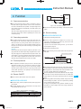
1
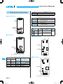
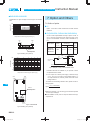
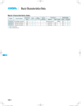
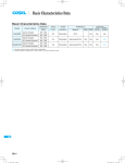
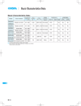
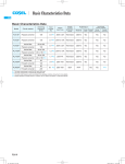
Basic Characteristics Data
Basic Characteristics Data
Model
Circuit method
Switching
frequency
[kHz]
Input
current
[A]
Rated
input fuse
Inrush
current
protection
circuit
Material
SNDHS50A
Forward converter
470
*1
400V 3.15A
-
SNDHS50B
Forward converter
470
*1
400V 1.6A
SNDHS100A
Forward converter
470
*1
SNDHS100B
Forward converter
470
SNDHS200A
Forward converter
SNDHS250B
Forward converter
*1 Refer to Specification.
*2 Refer to Instruction Manual.
SNDHS
SNDHS-14
Series/Parallel
operation availability
PCB/Pattern
Single
sided
Double
sided
Series
operation
Parallel
operation
FR-4
Yes
Yes
*2
-
FR-4
Yes
Yes
*2
400V 3.15A
-
FR-4
Yes
Yes
*2
*1
400V 1.6A
-
FR-4
Yes
Yes
*2
360
*1
400V 5.0A
-
FR-4
Yes
Yes
*2
360
*1
400V 3.15A
-
FR-4
Yes
Yes
*2
DC-DC Converters Bus Converter . Power Module Value-added Type
Instruction Manual
1
Terminal Connection
SNDHS-16
2
Connection for Standard Use
SNDHS-17
3
Wiring Input/Output Terminal
SNDHS-18
4
5
6
7
3.1
Wiring input terminal
SNDHS-18
3.2
Wiring output terminal
SNDHS-18
Function
SNDHS-19
4.1
Overcurrent protection
SNDHS-19
4.2
Overvoltage protection
SNDHS-19
4.3
Thermal protection
SNDHS-19
4.4
Remote ON/OFF
SNDHS-19
4.5
Remote sensing
SNDHS-19
4.6
Output voltage adjusting
SNDHS-20
4.7
Withstanding voltage / Isolation voltage
SNDHS-20
Series and Parallel Operation
SNDHS-20
5.1
Series operation
SNDHS-20
5.2
Redundancy operation
SNDHS-20
Implementation-Mounting Method
SNDHS-21
6.1
Mounting method
SNDHS-21
6.2
Derating
SNDHS-21
Option and Others
7.1
Outline of option
SNDHS-22
SNDHS-22
SNDHS-15
SNDHS
DC-DC Converters Bus Converter . Power Module Value-added Type
1 Terminal Connection
Instruction Manual
Pin configuration and functions of CN2 (Optional)
Pin No.
1
2
Function
+RC : +Remote ON/OFF
-RC : -Remote ON/OFF
¿SNDHS50A/100A
Pin configuration and functions of CN3
Pin No.
1
TB1
2
3
4
CN2 (optional)
-M
Function
: -Self sensing terminal. (Do not wire for
-S
+S
+M
external connection.)
: -Remote sensing
: +Remote sensing
: +Self sensing terminal. (Do not wire for
external connection.)
Mating connectors and terminals on CN2, CN3
1 2
Mating
Connector
Terminal
connector
TB2
CN2 B2B-XH-AM
XHP-2
CN3 B4B-XH-AM
XHP-4
¿SNDHS200A
Mfr.
Chain : SXH-001T-P0.6
Loose : BXH-001T-P0.6
Chain : SXH-001T-P0.6
Loose : BXH-001T-P0.6
¿SNDHS50B/100B
CN1
CN2
TB1
4
4
2
1
2
1
CN4 (optional)
1
CN2 (optional)
CN3
1 2
2
1 2
4
CN3 (optional)
1
TB2
Fig.1.1 Terminal connection (top view)
1 2
Table 1.1 Terminal connection and function
SNDHS
No.
SNDHS
SNDHS
50A/100A
1
2
3
4
5
200A
1
2
3
45
67
Terminal
connection
+VIN
-VIN
FG
+VOUT
-VOUT
¿SNDHS250B
CN1
CN5 (optional)
CN2
Function
+DC input
-DC input
Frame Ground
+DC output
-DC output
4
4
2
1
2
1
2 1
CN3 (optional)
1 2
CN4
4
1
1 2 3 4
Fig.1.2 Terminal connection (top view)
SNDHS-16
J.S.T.
DC-DC Converters Bus Converter . Power Module Value-added Type
Table 1.2 Terminal connection and function
No.
SNDHS
SNDHS
50B/100B
1
2
250B
12
34
Terminal
+VOUT
-VOUT
2 Connection for
Standard Use
Function
connection
+DC output
-DC output
¡In order to use the power supply, it is necessary to wire as shown
in Fig.2.1, Fig.2.2.
Pin configuration and functions of CN1 and CN2
Pin No.
1
2
3
4
Function
: Remote ON/OFF
: -Input Voltage
: No connection
: +Input Voltage
RC1
-VIN
NC
+VIN
Instruction Manual
¿SNDHS50A/100A/200A
Heatsink
CN1 and CN2 are connected internally.
SNDHS50A/100A/200A
+VIN +VOUT
Pin configuration and functions of CN3:Optional
Pin No.
1
2
Function
+RC2 : +Remote ON/OFF
-RC2 : -Remote ON/OFF
Load
DC IN
-VIN
-VOUT
Pin configuration and functions of CN4:Optional(SNDHS50B/100B)
Pin No.
1
2
Function
+RC3 : +Remote ON/OFF
-RC3 : -Remote ON/OFF
FG
Fig.2.1 Connection for standard use
¿SNDHS50B/100B/250B
Pin configuration and functions of CN4(SNDHS250B)
Pin No.
1
2
3
4
-M
Function
: -Self sensing terminal. (Do not wire for
-S
+S
+M
external connection.)
: -Remote sensing
: +Remote sensing
: +Self sensing terminal. (Do not wire for
Heatsink
SNDPG750
SNDPF1000
Load
AC(N)
50B/100B 250B
CN1 CN1
CN2 CN2
CN3 CN3
CN4 CN5
-
Connector
B3P4-VH
Mating
connector
VHR-4N
B2B-XH-AM XHP-2
CN4 B4B-XH-AM XHP-4
RC1
ENA
FG
FG
Heatsink
SNDHS50B/100B/250B
+VIN
Terminal
Mfr.
Chain : SVH-21T-P1.1
Loose : BVH-21T-P1.1
Chain : SXH-001T-P0.6
Loose : BXH-001T-P0.6
Chain : SXH-001T-P0.6
Loose : BXH-001T-P0.6
-VOUT
Fig.2.2 Connection 1 for standard use
Mating connectors and terminals on CN1, CN2, CN3, CN4 and CN5
SNDHS SNDHS
+VOUT
-VIN
-VOUT
external connection.)
Function
+RC3 : +Remote ON/OFF
-RC3 : -Remote ON/OFF
+VIN
AC IN
Pin configuration and functions of CN5:Optional(SNDHS250B)
Pin No.
1
2
SNDHS50B/100B/250B
AC(L) +VOUT
DC IN
+VOUT
Load
RC1
Vcc
-VIN
-VOUT
SNDHS
J.S.T.
FG
Fig.2.3 Connection 2 for standard use
¡The SNDHS Series handles only the DC input.
Avoid applying AC input directly.
It will damage the power supply.
¡Operate with the conduction cooling (e.g. heat radiation from the
aluminum base plate to the attached heat sink).
[Reference: 6.2 ”Derating”]
¡This power supply must be prepared another power supply to the
RC1 terminal (as shown in Fig.2.3).
[Reference:4.4 “Remote ON/OFF”]
¡If you need except SNDPG750/SNDPF1000 for the input of
SNDHS50B/100B/250B, please contact us.
*Confirm each specification and instruction manual about the
SNDPG/SNDPF series.
SNDHS-17
DC-DC Converters Bus Converter . Power Module Value-added Type
Instruction Manual
Input voltage range
Input current [A]
3 Wiring Input/Output Terminal
3.1 Wiring input terminal
lp
(1) External capacitor on the Input side
Input voltage [V]
¡When it turns on an input with a switch directly, one several times
the surge voltage of input voltage occurs by the inductance ingre-
Fig.3.2 Input current characteristics
dient of an input line, and there is a possibility that a power supply
DC
may break down.
YES
Please install a capacitor between +VIN and -VIN input terminals
SNDHS
Load
SNDHS
Load
SNDHS
Load
and absorb surge.
AC
SNDHS50B/100B : more than 10 μF
SNDHS250B
: more than 22 μF
NO
¡When the line impedance is high or the input voltage rise quickly
at start-up (less than 10us), install a capacitor between +VIN and
AC
AC
/DC
YES
-VIN input terminals.
(2) Input voltage range/Input current range
Fig.3.3 Use with AC input
¡The specification of input ripple voltage is shown as below.
Ripple voltage SNDHS50A/100A/200A : less than 10Vp-p
SNDHS50B/100B/250B : less than 20Vp-p
(a)
(b)
+VIN
DC IN
-VIN
¡Make sure that the voltage fluctuation, including the ripple voltage,
will not exceed the input voltage range.
Fig.3.4 Reverse input voltage protection
¡Use a front end unit with enough power, considering the start-up
current Ip of this unit.
3.2 Wiring output terminal
(3) Operation with AC input
¡The SNDHS series handles only for the DC input.
A front end unit(AC/DC unit) is required when the SNDHS series
is operated with AC input.
(4) Reverse input voltage protection
¡The specified ripple and ripple noise are measured by the method
introduced in Fig. 3.5.
0-150mm
[0-5.91 inches]
SNDHS
+VIN
+VOUT
¡Avoid the reverse polarity input voltage. It will break the power
supply.
It is possible to protect the unit from the reverse input voltage by
+M
+S
DC
Input voltage range
Input voltage [V]
Ripple
voltage
+
Co=22mF
installing an external diode.
SNDHS
+VIN
DC IN
-VIN
Load
-S
-M
-VIN
Oscilloscope
BW:100MHz
-VOUT
R
1.5m 50W
Coaxial Cable
C
time
Fig.3.1 Input voltage ripple
t
R=50W
C=0.01mF
+M, +S, -M, -S : SNDHS200A/SNDHS250B
Fig.3.5 Method of measuring output ripple and ripple noise
SNDHS-18
DC-DC Converters Bus Converter . Power Module Value-added Type
4 Function
Instruction Manual
+
+VIN
4
input -
-VIN
2
DC
SNDHS
External DC
4.1 Overcurrent protection
RC1 1
Vcc +
¡Over Current Protection (OCP) is built in and works at 105% of
the rated current or higher. However, use in an over current situa-
Fig. 4.1 RC1 connection example
tion must be avoided whenever possible. The output voltage of the
power module will recover automatically if the fault causing over
current is corrected.
CN1
SW
¡Avoid the reverse polarity input voltage. It will break the power
supply.
When the output voltage drops after OCP works, the power module enters a ”hiccup mode” where it repeatedly turns on and off at
a certain frequency.
4.5 Remote sensing
¿SNDHS250A/SNDHS250B
4.2 Overvoltage protection
(1) When Remote Sensing is Not Used
¡Over Voltage Protection (OVP) is built in. When OVP works, output voltage can be recovered by shutting down DC input for at
¡When the power supplies are shipped from a factory, they
come with a dedicated short pieces being mounted on CN3
least one second or by turning off the remote control switch (sec-
(SNDHS200A), CN4 (SNDHS250B).
ondary is an optional) for one second without shutting down the
If you do not use the remote sensing function, you can use the
DC input. The recovery time varies according to input voltage and
power supplies as they are.
input capacitance.
(2) When Remote Sensing is Used
Remarks:
Note that devices inside the power module may fail when a voltage greater than the rated output voltage is applied from an exter-
¡When remote sensing is used, please remove the short pieces of
CN3, CN4.
nal power supply to the output terminal of the power module. This
Wire as close as possible
could happen in in-coming inspections that include OVP function
test or when voltage is applied from the load circuit. OVP can be
tested by using the TRM terminal. Consult us for details.
SNDHS200A
SNDHS250B
+S
+VOUT
-VOUT
-S
4.3 Thermal protection
+
Co
Load
¡Over Temperature Protection (OTP) is built in. If the base plate
temperature exceeds 100C, OTP will work, causing the output
Fig. 4.2 When remote sensing is used ((SNDHS200A/SNDHS250B)
voltage to drop. Output voltage can be recovered by shutting
¡Using remote sensing with long wires may cause output voltage to
become unstable. Consult us if long sensing wiring is necessary.
down DC input for at least one second or by turning off the remote
control switch (secondary is an optional) for one second without
shutting down the DC input.
¡Sensing patterns or wires should be as short as possible. If wires
are used, use either twisted-pair or shielded wires.
4.4 Remote ON/OFF
¡Use wide PCB patterns or thick wires between the power supply
and the load. Line drop should be kept less than 0.3V. Make sure
¡Please contact us about remote control of an optional.
output voltage from the power supply stays within the specified
range.
¡If the sensing patterns are shorted by mistake, a large current may
flow and damage the pattern. This can be prevented by installing
¿SNDHS50B/100B/250B
¡This power supply must be prepared another power supply to the
RC1 terminal.
fuses or resistors close to the load.
¡The remote ON/OFF function is incorporated in the input circuit
and operated with RC1 and -VIN.
fluctuations in output voltage, make sure enough evaluation is
As wiring or load impedance may generate oscillation or large
given in advance.
Table 4.1 Remote ON/OFF specifications
Between RC1 and -VIN (Vcc)
L level (0 - 1.2V) or Open
H level (3.5 - 12V)
Output Voltage
OFF
ON
¡When RC1 is at High level, a current of 13mA max will sink in.
SNDHS-19
SNDHS
DC-DC Converters Bus Converter . Power Module Value-added Type
4.6 Output voltage adjusting
¡Output voltage can be adjusted by internal potentiometer.
To increase an output voltage, turn a built-in potentiometer clockwise.
Instruction Manual
5 Series and Parallel
Operation
To decrease the output voltage, turn it counterclockwise.
¡When the input voltage is 60-66VDC or 200-250VDC, the output
voltage adjustment range becomes as shown in Fig.4.3.
100
90
60
63
66
Input voltage [V]
SNDHS50A/100A
110
Others
100
connection should be lower than the lowest rated current in each
unit.
(a)
Power
Supply
90
0
0
60
63
66
Input voltage [V]
Load
110
0
0
¡Series operation is available by connecting the outputs of two or
more power supplies, as shown below. Output current in series
5V
Adjustment range [%]
Adjustment range [%]
5V,12V,15V,24V
5.1 Series operation
Power
Supply
SNDHS200A
(b)
Load
Power
Supply
Others
100
90
0
0
200
225
Load
Adjustment range [%]
3.3,5V
110
Power
Supply
250
Input voltage [V]
Fig. 4.3 Output voltage adjustment range
4.7 Withstanding voltage / Isolation voltage
¡When testing the withstanding voltage, make sure the voltage is
increased gradually. When turning off, reduce the voltage gradually by using the dial of the hi-pot tester. Do not use a voltage tester
with a timer as it may generate voltage several times as large as
Fig. 5.1 Examples of series operation
5.2 Redundancy operation
¡Parallel operation is not possible.
¡Redundancy operation is available by wiring as shown below.
I1
I3
+VOUT
-VOUT
Load
SNDHS50B/100B/250B
the applied voltage.
I2
+VOUT
-VOUT
SNDHS
Fig. 5.2 Example of redundancy operation
¡Even a slight difference in output voltage can affect the balance
between the values of I1 and I2.
Please make sure that the value of I3 does not exceed the rated
current of a power supply.
I3
SNDHS-20
the rated current value
DC-DC Converters Bus Converter . Power Module Value-added Type
6 ImplementationMounting Method
Instruction Manual
¿SNDHS50A/100A/200A
Specifications for ripple and ripple noise changes in the shaded
area.
6.1 Mounting method
¡The unit can be mounted in any direction. When two or more
power supplies are used side by side, position them with proper
Load factor [%]
100
intervals to allow enough air ventilation. Aluminum base plate temperature (Point A) around each power supply should not exceed
2 1
3
1SNDHS50A/100A
2SNDHS200A05
3SNDHS200A12, 15, 24
70
50
15
0
-20
0
20
40
60 (70) 80
9095
Temperature of measureing point (Point A) [C]
the temperature range shown in derating curve (Fig6.2, Fig.6.4).
¡In case of metal chassis, keep the distance between d1 for to
insulate between lead of component and metal chassis, use the
TB2
TB1
spacer of 4mm[0.16 inches] or more between d1. If it is less than
d1, insert the insulation sheet between power supply and metal
d1
chassis.
Point A
Measuring Point
d1
Fig.6.2 Derating curve (Point A)
d1
d1
Load factor [%]
100
50
d1
0
- 20
d1=4mm [0.16 inches] min.
-10
0
10
20
30
40
50
60
70
Temperature of measureing point (Point B) [C]
Figure is SNDHS250B
Fig.6.1 Mounting method
6.2 Derating
TB1
¡Use with the conduction cooling (e.g. heat radiation by conduction
from the aluminum base plate to the attached heat sink).
SNDHS
Fig.6.2, Fig.6.4 shows the derating curve based on the aluminum
Point B
Measuring Point
base plate temperature. In the hatched area, the specification of
Ripple and Ripple Noise is different from other areas.
¡Please measure the temperature on the aluminum base plate
edge side (Point A).
¡Please consider the ventilation to keep the temperature on the
PCB (Point B) less than the temperature of Fig.6.3., Fig.6.5.
¡It is necessary to note the thermal fatigue life by power cycle.
Please reduce the temperature fluctuation range as much as possible when the up and down of the temperature are frequently
TB2
Figure is SNDHS200A
generated.
Contact us for more information on cooling methods.
Fig.6.3 Derating curve (Point B)
SNDHS-21
DC-DC Converters Bus Converter . Power Module Value-added Type
¿SNDHS50B/100B/250B
Specifications for ripple and ripple noise changes in the shaded
Instruction Manual
7 Option and Others
area.
Load factor [%]
100
2 1
3
1SNDHS50B
2SNDHS100B
3SNDHS250B
70
50
15
0
-20
0
20
40
7.1 Outline of option
¿ -C
-Option -C units have coated internal PCB for better moisture
resistance.
60 (70) 80
9095
¿ -R (SNDHS50A, SNDHA100A,SNDHS200A)
-You can control output ON/OFF remotely in Option -R units. To
do so, connect an external DC power supply and apply a volt-
Temperature of measureing point (Point A) [C]
age to a remote ON/OFF connector, which is available as opTB1
CN2
tion.
Model Name
Built-in
Resistor
Ri [ W ]
Voltage between +RC
Input
and -RC [V]
Current
[mA]
ENA ON
ENA OFF
SNDHS50A,
Point A
SNDHS100A,
Measuring Point
1200
3.5 - 12
0 - 0.5
10max
SNDHS200A
Fig.6.4 Derating curve (Point A)
R*1
Load factor [%]
100
External Power
Source
SW
+RC 1
Inside of a Power
Supply
Ri
Input Current
-RC 2
50
Remote ON/OFF connector (Optional)
Fig.7.1 Example of using a remote ON/OFF circuit
0
- 20
-10
0
10
20
30
40
50
60
Temperature of measureing point (Point B) [C]
CN1
70
-Dedicated harnesses are available for your purchase. Please
see Optional Parts for details.
*1 If the output of an external power supply is within the range
of 3.5 - 12V, you do not need a current limiting resistor R. If
CN2
the output exceeds 12V, however, please connect the current
limiting resistor R.
To calculate a current limiting resistance value, please use the following equation.
SNDHS
R[W]=
Point B
Vcc-(1.1+RiX0.005)
0.005
Measuring Point
*Please wire carefully. If you wire wrongly, the internal components
of a unit may be damaged.
¡Remote ON/OFF circuits (+RC and -RC) are isolated from input,
output and FG.
TB1
Figure is SNDHS250B
Fig.6.5 Derating curve (Point B)
SNDHS-22
DC-DC Converters Bus Converter . Power Module Value-added Type
¿ -R (SNDHS50B, SNDHA100B,SNDHS250B)
-The output can be turned on without external power source.
-When short circuit piece is not mounted on RC3, various remote
control is available.
Instruction Manual
*Please wire carefully. If you wire wrongly, the internal components
of a unit may be damaged.
¡Remote ON/OFF circuits (+RC2 and -RC2 only) are isolated from
input, output and FG.
Case 1:When short circuit piece is mounted on RC3, the output
can be turned on by applying input voltage (external
power source to the remote control circuit is unnecessary).
When the power supplies are shipped from a factory,
they come with a dedicated short circuit piece mounted
on RC3.
Case 2:When short circuit piece is mounted on RC3, the output
(ON/OFF) can be controlled by making open/short RC3.
Case 3:When short circuit piece is not mounted on RC3, the
output (ON/OFF) can be controlled by external power
source to remote control circuit RC1 and RC2.
CASE
RC3
RC1 RC2
OUTSIDE OF
INSIDE OF
SHORT
RC3 DC
DC OUTPUT POWER SUPPLY POWER SUPPLY
CIRCUIT
VOLTAGE VOLTAGE
PIECE
1
RC1
-Vin
1 mounted Short
-
-
2
Ri1:750W
1
Ri2:1200W
+RC2
ON
-RC2
2
1
Short
Circuit
piece
+RC3
-RC3
2
1
RC1
ON
Short
1.2[V]
2
0.5[V]
+RC2
or less or less
-RC2
Open
R1*1
12[V]
3
Open
ON
Vcc
DC Voltage
3.5 ~
Vcc
DC Voltage
0.5[V]
or less
OFF
2
2
1
RC1
-Vin
R2*1
12[V]
Ri2:1200W
+RC3
-RC3
3.5 ~
Ri1:750W
1
1
OFF
not
mounted
2
-Vin
+RC2
-RC2
2
Ri1:750W
1
Ri2:1200W
2
1
+RC3
-RC3
SNDHS
2
Fig.7.2 Example of using a remote ON/OFF circuit.
-Dedicated harnesses are available for your purchase. Please
see Optional Parts for details.
*1 If the output of an external power supply is within the range of
3.5 - 12V, you do not need a current limiting resistor R1, R2.
If the output exceeds 12V, however, please connect the current limiting resistor R1, R2.
To calculate a current limiting resistance value, please use the following equation.
R1, R2[W]=
Vcc-(1.1+Ri1,Ri2X0.005)
0.005
SNDHS-23