1
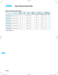
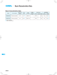
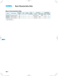
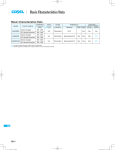
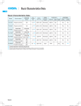
Basic Characteristics Data
Basic Characteristics Data
Model
Circuit method
Switching
frequency
[kHz]
Rated
input fuse
Inrush
current
protection
Material
SNDPG750
Active filter
130
250V 12A
SCR
FR-4
SNDPG
SNDPG-4
Series/Parallel
operation availability
PCB/Pattern
Single
sided
Double
sided
Series
operation
Parallel
operation
Yes
No
No
AC-DC Power Supplies Bus Converter . Power Module Value-added Type
Instruction Manual
1
Terminal Connection
SNDPG-6
2
Input Voltage Derating
SNDPG-6
3
Standard Connection Method
SNDPG-6
4
5
6
3.1
Standard connection method
SNDPG-6
3.2
Connection of loaded circuit
SNDPG-6
3.3
Heatsink
SNDPG-6
Function
SNDPG-7
4.1
Overcurrent protection
SNDPG-7
4.2
Overvoltage protection
SNDPG-7
4.3
Thermal protection
SNDPG-7
4.4
Enable signal (ENA)
SNDPG-7
4.5
Isolation
SNDPG-7
Series and Parallel Operation
SNDPG-7
5.1
Series operation
SNDPG-7
5.2
Parallel operation
SNDPG-7
Implementation-Mounting Method
SNDPG-7
6.1
Mounting method
SNDPG-7
6.2
Derating
SNDPG-8
SNDPG
7
Optional and Others
7.1
Outline of option
SNDPG-9
SNDPG-9
SNDPG-5
AC-DC Power Supplies Bus Converter . Power Module Value-added Type
1 Terminal Connection
8
7
1 2 3
CN2
CN1
Instruction Manual
2 Input Voltage Derating
¡Fig.2.1 shows rated output for each input voltage section.
5
6
Output power [W]
4
750
500
85
170
Input Voltage [AC V]
Fig.2.1 Input voltage derating curve (SNDPG750)
3 Standard Connection
Method
Fig.1.1 Terminal connection (top view)
3.1 Standard connection method
¡To use SNDPG Series, connection shown in Fig.3.1. Through this
connection, DC output voltage can be obtained from AC input voltage.
Table 1.1 Terminal connection and functions
Terminal
connection
No.
Function
AC input voltage and DC output voltage are not insulated.
1
FG
2
AC(N)
3
AC(L)
4
+VOUT
+DC output
5
-VOUT
-DC output
6
ENA
Enable signal
FG
Heatsink
AC Input
SNDPG750
(L)
+V
+V
-V
-V
AC IN
(N)
ENA
7
+RC
Remote ON/OFF (+RC) Optional
8
-RC
Remote ON/OFF (-RC) Optional
Pin No.
1
2
3
4
ENA
-V
NC
+V
RC1(SNDHS series)
ENA(SNDBS series)
FG
FG
Fig.3.1 Standard connection method
Table 1.2 Pin configuration and functions of CN1
SNDPG
SNDHS series
SNDBS series
¡Confirm each specification and instruction manual about the SNDHS/
Function
: Enable signal
: -DC OUTPUT (-VOUT)
: No connection
: +DC OUTPUT (+VOUT)
SNDBS series.
3.2 Connection of loaded circuit
Table 1.3 Pin configuration and functions of CN2 (optional)
¡For connecting the SNDHS series (SNDHS50B / 100B / 250B)
and SNDBS series, see Fig.3.1.
Pin No.
1
2
¡Control load current so that it may flow only when the terminal
ENA is at “H”. At “L” when inrush current protection circuit is not
+RC
-RC
Function
: Remote ON/OFF (+RC)
: Remote ON/OFF(-RC)
released, excessive current may be applied to the circuit.
Table 1.4 Mating connectors and terminals of CN1 and CN2
Connector
Mating
connector
CN1 B3P4-VH
VHR-4N
CN2 B2B-XH-AM
XHP-2
Terminal
Mfr.
3.3 Heatsink
Chain:SVH-21T-P1.1
Loose:BVH-21T-P1.1
Chain:SXH-001T-P0.6
Loose:BXH-001T-P0.6
¡For connection of loads except the SNDHS series and SNDBS
series, please contact us.
J.S.T.
¡The power supply adopts the conduction cooling system.
Attach a heatsink to the aluminum base plate to cool the power
supply for use.
Refer to 6.2 Derating.
SNDPG-6
AC-DC Power Supplies Bus Converter . Power Module Value-added Type
Instruction Manual
4.5 Isolation
4 Function
¡For a receiving inspection, such as Hi-Pot test, gradually increase
(decrease) the voltage for a start (shut down). Avoid using Hi-Pot
tester with the timer because it may generate voltage a few times
4.1 Overcurrent protection
higher than the applied voltage, at ON/OFF of a timer.
¡The overcurrent protection circuit is not built-in.
4.2 Overvoltage protection
¡The overvoltage protection circuit is built-in. The AC input should
be shut down if overvoltage protection is in operation.
When this function operates, the power factor corrector function
5 Series and Parallel
Operation
does not operate, and output voltage becomes the full-wave rectified AC input voltage.
5.1 Series operation
Remarks:
Please note that the unit’s internal components may be damaged
¡As input and output are not insulated, series operation is impossible.
if excessive voltage (over rated voltage) is applied to output terminal of power supply. This could happen when the customer tests
the overvoltage performance of the unit.
5.2 Parallel operation
¡Parallel operation is not possible.
4.3 Thermal protection
¡Thermal protection circuit is built-in and it operates about 115C.
If this function comes into effect, shut down the output, eliminate
all possible causes of overheating, and drop the temperature to
normal level. To prevent the unit from overheating, avoid using the
unit in a dusty, poorly ventilated environment.
When this function operates, the power factor corrector function
6 ImplementationMounting Method
does not operate, and output voltage becomes the full-wave rectified AC input voltage and ENA output changes into "L".
6.1 Mounting method
¡The unit can be mounted in any direction. When two or more
power supplies are used side by side, position them with proper
4.4 Enable signal (ENA)
¡Use ENA to control starting of the loaded power supply.
¡When inrush current protection circuit is released, ENA outputs
“Hight” .
intervals to allow enough air ventilation. Aluminum base plate temperature (Point A) around each power supply should not exceed
the temperature range shown in derating curve.
¡If load current flows without releasing of the circuit, the resistor
may be burnt.
¡In case of metal chassis, keep the distance between d1 for to insulate between lead of component and metal chassis. If it is less
than d1, insert the insulation sheet between power supply and
No.
1
2
3
4
Table 4.1 Specification of ENA
Item
ENA
Output possible "H"
Function
Output prohibited "L"
Base pin
-VOUT
Level voltage "H"
10V typ (at no load)
Level voltage "L"
0V typ
metal chassis.
2.2kW
12V
10kW
ENA
-VOUT
Fig.4.1 Internal circuit of ENA
SNDPG-7
SNDPG
d1
AC-DC Power Supplies Bus Converter . Power Module Value-added Type
Instruction Manual
Load factor [%]
100
80
60
40
d1
20
0
-20
0
20
40
60
80
(95) 100
Temperature of measureing point (Point A) [C]
CN1
d1
TB1
d1
Point A
Measuring point
d1
Fig.6.2 Derating curve (Point A)
d1=4mm [0.16 inches] min.
Fig.6.1 Mounting method
6.2 Derating
Load factor [%]
100
50
0
- 20
¡Use with the conduction cooling (e.g. heat radiation by conduction
from the aluminum base plate to the attached heat sink).
-10
0
10
20
30
40
50
60
70
Temperature of measureing point (Point B) [C]
Fig.6.2 shows the derating curve based on the aluminum base
plate temperature.
¡Please measure the temperature on the aluminum base plate
edge side (Point A).
Please consider the ventilation to keep the component tempera-
SNDPG
CN1
TB1
ture on the PCB (Point B) less than the temperature of Fig.6.3.
¡It is necessary to note the thermal fatigue life by power cycle.
Please reduce the temperature fluctuation range as much as pos-
Point B
Measuring
point
sible when the up and down of the temperature are frequently
generated.
Contact us for more information on cooling methods.
Fig.6.3 Derating curve (Point B)
SNDPG-8
AC-DC Power Supplies Bus Converter . Power Module Value-added Type
Instruction Manual
7 Optional and Others
7.1 Outline of option
¿ -C
-Option -C units have coated internal PCB for better moisture
resistance.
¿ -R
-You can control enable signal (ENA) ON/OFF remotely in Option
-R units. To do so, connect an external DC power supply and
apply a voltage to a remote ON/OFF connector, which is available as option.
Built-in Resistor
Ri [ W ]
Voltage between +RC
and -RC [V]
ENA ON
ENA OFF
1200
3.5 - 12
R*1
External Power
Source
0 - 0.5
SW
+RC 1
Input Current
[mA]
10max
Inside of a Power
Supply
Ri
Input Current
-RC 2
Remote ON/OFF connector (Optional)
Fig.7.1 Example of using a remote ON/OFF circuit
-Dedicated harnesses are available for your purchase. Please
see Optional Parts for details.
*1 If the output of an external power supply is within the range
of 3.5 - 12V, you do not need a current limiting resistor R. If
the output exceeds 12V, however, please connect the current
limiting resistor R.
To calculate a current limiting resistance value, please use the following equation.
R[W]=
SNDPG
Vcc-(1.1+RiX0.005)
0.005
*Please wire carefully. If you wire wrongly, the internal components
of a unit may be damaged.
¡Remote ON/OFF circuits (+RC and -RC) are isolated from input,
output and FG.
SNDPG-9