1
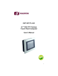
GOT-3570T 5.7” QVGA TFT Fanless Touch Panel computer User’s Manual Disclaimers The information in this manual has been carefully checked and is believed to be accurate. AXIOMTEK Co., Ltd. assumes no responsibility for any infringements of patents or other rights of third parties, which may result from its use. AXIOMTEK assumes no responsibility for any inaccuracies that may be contained in this document. AXIOMTEK makes no commitment to update or to keep current the information contained in this manual. AXIOMTEK reserves the right to make improvements to this document and/or product at any time and without notice. No part of this document may be reproduced, stored in a retrieval system, or transmitted, in any form or by any means, electronic, mechanical, photocopying, recording, or otherwise, without the prior written permission of AXIOMTEK Co., Ltd. ©Copyright 2007 by AXIOMTEK Co., Ltd. All rights reserved. September 2007, Version A1 Printed in Taiwan ii Safety Approvals CE Marking FCC Class A FCC Compliance This equipment has been tested and complies with the limits for a Class A digital device, pursuant to Part 15 of the FCC Rules. These limits are designed to provide reasonable protection against harmful interference in a residential installation. If not installed and used in accordance with proper instructions, this equipment might generate or radiate radio frequency energy and cause harmful interference to radio communications. However, there is no guarantee that interference will not occur in a particular installation. If this equipment does cause harmful interference to radio or television reception, which can be determined by turning the equipment off and on, the user is encouraged to try to correct the interference by one or more of the following measurers: 1. Reorient or relocate the receiving antenna. 2. Increase the separation between the equipment and receiver. 3. Connect the equipment into an outlet on a circuit different from that to which the receiver is connected. 4. Consult the dealer or an experienced radio/TV technician for help. Shielded interface cables must be used in order to comply with emission limits.ou iii Safety Precautions Before getting started, read the following important cautions. 1. The GOT-3570T does not come equipped with an operating system. An operating system must be loaded first before installing any software into the computer. 2. Be sure to ground yourself to prevent static charge when installing the internal components. Use a grounding wrist strap and place all electronic components in any static-shielded devices. Most electronic components are sensitive to static electrical charge. 3. Disconnect the power cord from the GOT-3570T before making any installation. Be sure both the system and the external devices are turned OFF. Sudden surge of power could ruin sensitive components. Make sure the GOT-3570T is properly grounded. 4. The brightness of the flat panel display decreases with usage. However, hours of use vary depending on the application environment. 5. Turn OFF the system power before cleaning. Clean the system using a cloth only. Do not spray any liquid cleaner directly onto the screen. The GOT-3570T comes with a touch screen. Although the touch screen is chemical resistant, it is recommended that you spray the liquid cleaner on a cloth first before wiping the screen. In case your system comes without the touch screen, you must follow the same procedure and not spray any cleaner on the flat panel directly. 6. Avoid using sharp objects to operate the touch screen. Scratches on the touch screen may cause malfunction or internal failure to the touch screen. 7. The flat panel display is not susceptible to shock or vibration. When assembling the GOT-3570T, make sure it is securely installed. iv 5. Do not open the system’s back cover. If opening the cover for maintenance is a must, only a trained technician is allowed to do so. Integrated circuits on computer boards are sensitive to static electricity. To avoid damaging chips from electrostatic discharge, observe the following precautions: 9 Before handling a board or integrated circuit, touch an unpainted portion of the system unit chassis for a few seconds. This will help to discharge any static electricity on your body. 9 When handling boards and wrist-grounding strap, available component stores. components, from most wear a electronic Trademarks Acknowledgments AXIOMTEK is a trademark of AXIOMTEK Co., Ltd. IBM, PC/AT, PS/2, VGA are trademarks of International Business Machines Corporation. Intel and Pentium are trademarks of Intel Corporation. MS-DOS, Microsoft C and Quick BASIC are trademarks of Microsoft Corporation. VIA is a trademark of VIA Technologies, Inc. SST is a trademark of Silicon Storage Technology, Inc. UMC is a trademark of United Microelectronics Corporation. Other brand names and trademarks are the properties of their respective owners. v This page does not contain any information. vi Table of Contents Disclaimers ........................................................................ii Safety Approvals................................................................iii FCC Compliance ..............................................................iii Safety Precautions ............................................................. iv Chapter 1 .....................................................................1 Introduction ..........................................................................1 1.1 1.2 General Description ............................................1 Specifications ......................................................2 1.2.1 1.2.2 1.2.3 1.3 1.4 1.5 Main CPU board....................................................2 I/O System .............................................................2 System Specification ............................................3 Dimensions ..........................................................3 I/O Outlets ............................................................5 Package list..........................................................6 Chapter 2 .....................................................................7 Hardware Installation .........................................................7 2.1 2.2 2.3 2.4 2.5 CompactFlash Card Installation ........................8 PC/104 Installation ..............................................9 Serial Port Interface ..........................................10 Ethernet ..............................................................11 Mounting Way : Panel mount...........................11 Chapter 3 ...................................................................12 Windows CE.Net................................................................12 3.1 3.2 Survey Form.......................................................12 Calibrate Touch Screen ....................................12 Table of Contents vii GOT-3570T User’s Manual Chapter 1 Introduction This chapter contains the general information and the detail specifications of the GOT-3570T. Chapter 1 includes the following sections: 1.1 General Description System Specification Dimensions I/O Outlets Package List General Description The GOT-3570T is a 5.7” fanless TFT QVGA touch panel computer. It is equipped with CISI-based low power consumption processor, AMD LX800. By supporting the option of external battery set, the GOT-3570T can continue system operation if a main power shortage ever happens. In addition, the PC/104 and Mini-PCI slots are reserved for expansion availability. The GOT-3570T supports CompactFlash card and is the best choice for applications of factory automation, machinery maker, building automation and semi-conductor. Introduction 1 GOT-3570T User’s Manual 1.2 1.2.1 Specifications Main CPU board CPU: AMD LX800 500MHz System Chipset: AMD LX + CS5536AD BIOS: Phoenix-Award 4Mbit with RPL/PXE Ethernet Boot ROM, Smartview and customer CMOS backup. System Memory: One 184-pin DDR DIMM Maximum up to 1GB 1.2.2 I/O System Standard I/O: − 2 x serial ports (1 x RS-232, 1 x RS-232/422/485) − 2 x USB Ports 2.0 compliant Ethernet: Equipped with 1 x RJ-45 for 10/100 base-T Audio: Realtek AC’97 codec audio (Line-out) Expansion: Equipped with 1 x Mini-PCI & 1 x PC/104 Compact Flash Socket: One Compact Flash Type II Socket 2 Introduction GOT-3570T User’s Manual 1.2.3 System Specification 5.7” QVGA TFT LCD Disk drive housing: − 1 x Compact Flash Type II Socket DC 24V power supply Heat dispensing design Net weight: − 2.0 Kgs Dimension (main body size): − 208.5 x 167.3 x 66.5 mm Operating temperature: − O° to 45°C ; Relative umidity:50% Relative humidity: − 10% to 85% @ 40° C, non-condensing Altitude: − 10,000 ft. (3,000 meters) Vibration (operating): − 5 to 500 Hz, 1 G random Shock (operating): − 10 G peak acceleration (11 msec. duration) 1.3 Dimensions The following diagrams show the dimensions and outlines of GOT-3570T. Introduction 3 GOT-3570T User’s Manual 4 Introduction GOT-3570T User’s Manual 1.4 I/O Outlets The following figure shows the I/O locations of the GOT-3570T. 1: Power Switch 6: LAN 2: DC power connector 7: USB 2.0 x 2 3: COM 2 (RS-232) 8: Line-out 4: COM 1 (RS-232/422/485) 9: CompactFlash card 5: PC/104 slot Introduction 5 GOT-3570T User’s Manual 1.5 Package list When you receive the GOT-3570T, there are following items in the package. If you can not find it, please contact AXIOMTEK distributors. 1. GOT-3570T x 1 2. Panel mount kit x 6 3. Driver CD x1 6 Introduction GOT-3570T User’s Manual Chapter 2 Hardware Installation The GOT-3570T provides rich I/O ports and flexible expansions for you to meet different demand such as PCMCIA, WLAN module and so on. The chapter will show you how to install the hardware. It includes : CompactFlash Card PC/104 Serial Port Ethernet Mounting Way Hardware Installation 7 GOT-3570T User’s Manual 2.1 CompactFlash Card Installation GOT-3570T offers one CF slot for users to install CompactFlash card. Please refer to the following instructions and illustration: 1. Remove the rubber cover at left-side. 2. Install CompactFlash card in the GOT-3570T. 8 Hardware Installation GOT-3570T User’s Manual 2.2 PC/104 Installation The GOT-3570T offers a convenient expansion for users to install PC/104 module such as PCMCIA, WLAN, COM port card and so on. Please follow the steps: 1. Unscrew screws to remove the bracket. 2. Install PC/104 module. Hardware Installation 9 GOT-3570T User’s Manual 2.3 Serial Port Interface The GOT-3570T has two onboard (RS-232/422/485) & COM2 (RS-232). serial ports, COM1 The pin assignments are listed below: Description 1 Data Carrier Detect (DCD) 2 Receive Data (RXD) 3 Transmit Data (TXD) 4 Data Terminal Ready (DTR) 5 Ground (GND) 6 Data Set Ready (DSR) 7 Request to Send (RTS) 8 Clear to Send (CTS) 9 Ring Indicator (RI) In addition, COM1 can be set for RS-232/422/485 by jumper. The jump setting is listed as below: COM1 JP12 JP10 JP11 RS-232 (default) 1-2 3-5, 4-6 3-5, 4-6 RS-422 3-4, 7-8 1-3, 2-4 1-3, 2-4 RS-485 5-6, 7-8 1-3, 2-4 1-3, 2-4 COM2 10 COM1 Hardware Installation GOT-3570T User’s Manual 2.4 Ethernet The GOT-3570T provides an NE2000 compatible Ethernet (RJ-45) interface. For network connection, just plug in one cable end of the GOT-3570T 10/100 Base-T Hub into the standard RJ-45 connector. The pin assignment of the RJ-45 is listed below; Pin Signal 1 TX+ (Data transmission positive 2 TX- (Data transmission negative) 3 Rx+(Data reception positive) 4 RJ45 termination 5 RJ45 termination 6 Rx- (Data reception negative) 7 RJ45 termination 8 RJ45 termination 1 2 3 4 5 6 7 8 RJ-45 2.5 Mounting Way : Panel mount The GOT-3570T is designed for panel mount application. To mount the GOT-3570T, the standard set of mounting kit (included in the system packaging) is needed. Hardware Installation 11 GOT-3570T User’s Manual C h a p t e r 3 Windows CE.Net 3.1 Survey Form CompactFlash Card System Memory Support Multiple I/O USB 2.0 Keyboard & Mouse Display (MS Flat) Ethernet Audio Touch Screen 3.2 32MB ~ 2GB 256MB ~ 1GB Parallel Port 3 x UARTs compliant Serial Ports 2 x USB 1.1 PS/2 Keyboard & Mouse USB Keyboard & Mouse 320 x 240 Realtek 8139x/810x 10/100M Line-out 5-wire Resistive type Calibrate Touch Screen This image includes a Touch Screen on COM3. To calibrate it, do the following steps: 1. Start\Programs\PenMount TouchPanel\Calibration 2. 3 types of calibration mode selection (4/9/16 points) 12 Appendix