1
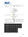
b. MOUNTING WITH CLIPS Base profile should be placed in perpendicular to the longer side frame of module in principle. Module shall be fixed at 4 places or more on the longer side frames. Refer to the figure and table for the allowable area to be fixed. Close the gap between the material and frame, and secure without losing by M6 or larger bolts (M8) for where the heavy snow load is expected. The clip centerlines must be between 1/8L and 1/4L on the long sides of the modules. Note that the mounting clips should meet the minimum dimensions (catch width of 5mm and length of 30mm). Use the clipping material with sufficient strength and the shape that can withstand forces from wind pressure and snowfall pressure specific to local climate. The tightening torque (using stainless steel M8) must be more than 15 Nm. Add some measure to prevent the module from unfastening or sliding down so that the fallen module doesn’t cause any damage for person or property. Fig. 2 Clipping method 3. c. INSTALLATION SUPPORT AT SEA-SIDE(SAIL MIST AND HIGH WIND) CONDITION If mounting with bolts, all 8 mounting holes must be used with M8 bolts. If mounting with clamps, the tightening torque (using stainless steel M8) must be more than 15 Nm. The oxidation film of PV modules’ frame must be more than 16 micron. All mounting structure and installation components must be hot galvanized before used. ELECTRICAL INSTALLATION WARNING Safety class in accordance with IEC 61140 Only authorized and trained personnel should have access to PV modules. The system involves electricity, and can be dangerous if the personnel are not familiar with the appropriate safety procedures. A. GROUNDING All module frames must be properly grounded. Observe all local electric codes and regulations. A bonding or toothed washer is required to make proper and reliable electrical grounding connection with the anodized aluminum frame. a. Devices listed and identified for grounding metallic frames of PV modules are permitted to ground the exposed metallic frames of the module to grounded mounting structure. Grounding the module properly as appropriate for the conditions t the installation site. Method #1 Secure the stainless steel screw to the grounding hole. As shown in the figure 3, copper wire should be compressed by the screw head. Stainless steel washer with appropriate corrosion resistant coating should be inserted between copper wire and the frame to avoid galvanic corrosion. Proper cupped washer should be inserted between copper wire and screw head. Fig. 3 Grounding method #1 2/4 www.just-solar.net