1
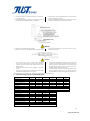
b. Method #2 If the mounting holes are not used to fix the module, one of them can be used for grounding. The appropriate device like “grounding lug” as shown in the figure 4 should be secured by stainless steel bolt, nut and washers. Toothed washer shall be inserted between the nut and the frame to break the anodized layer of frame. Stainless steel washer with appropriate corrosion resistant coating should be inserted between the grounding lug and frame. Fig. 4 Grounding method #2 WARNING DO NOT short the positive and negative cables. Make sure connectors are fully engaged without a gap between the insulators and shall be locked. In case there is a gap, a fire or an eletrical shock may occur. CAUTION The PV module has a pair of male and female waterproof connectors. For a series electrical connection, connect the positive connector of the first PV module to the negative connector of the following module. Connect the output cable to the other equipment in the system correctly. Connect the required number of PV modules to meet the voltage specification for equipment used in the PV system. Wire the output cable connectors so that they do not exert any force or pressure on the PV module’s junction box. Attach the cable to the mounting frame using approved fasteners. The connectors should be placed behind the mounting frame so that the connectors can’t be directly exposed to sunlight, wind and rain. To extend the cable, use proper commercial cables and connectors that can withstand outdoor use for long periods. Select the appropriate cable size according to its length to avoid voltage drop. Note: For field connection use minimum No. 10 AWG copper wires insulated for a minimum of 90°C. B. ELECTRICAL RATINGS OF THE CONCERNED MODULES Type JST-M160M JST- M165M JST- M170M JST-M175M JST-M180M Max Power Pm(W) 160 165 170 175 180 185 Max-Power Voltage Vm(V) 34.9 35.6 35.8 36.2 36.8 37.5 Max-Power Current Im(A) 4.60 4.65 4.76 4.85 4.90 4.95 Open-Circuit Voltage Voc(V) 42.8 43.2 43.6 43.9 44.2 44.5 Short-Circuit Current Isc(A) 5.15 5.20 5.25 5.30 5.35 5.40 15.0% 15.5% 16.0% 16.5% 17.0% 17.5% Cell Efficiency Maximum System Voltage(V) 1000(TUV)/600(UL) Maximum Series Fuse Rating(A) 15 Power Tolerance Type ±3% JST-M180P JST-M190P JST-M200P Max Power Pm(W) 180 190 200 210 Max-Power Voltage Vm(V) 26.5 26.8 27.2 27.5 Max-Power Current Im(A) 6.80 7.10 7.36 7.63 Open-Circuit Voltage Voc(V) 32.4 32.5 32.7 32.8 Short-Circuit Current Isc(A) 7.60 7.72 7.86 7.98 13.7% 14.5% 15.2% 16.0% Cell Efficiency Maximum System Voltage(V) Maximum Series Fuse Rating(A) Power Tolerance JST-M185M JST-M210P 1000(TUV)/600(UL) 20 ±3% 3/4 www.just-solar.net