1
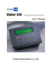
Cipher-520
Programmable Terminal
User’s Guide
Syntech Information Co., Ltd.
1. Packaging
This pack includes:
(1) This User's Guide
(2) The User’s Manual Disk
(3) The Cipher-520 main unit
(4) Optional slot reader mounted on the top of
Cipher-520 main unit (if ordered)
(5) The backup battery pack (if ordered)
(6) Power Adaptor (110VAC or 220VAC)
(7) Default System Master Card (1234567890)
1
2. Components
2.1. Front View
1. Red and Green LED for status
indication
3. Optional slot-type reader
(barcode or magnetic card)
5. Volume
7. External PC/AT keyboard
connector
9. Reader port #2
2. LCD display (240 X 64 or 128 X
64)
4. Keyboard
6. External ear-phone connector
8. Reader port #1
2
2.2. Rear View
1.
3.
5.
7.
Optional Operational Battery
COM2 connector
Digital input/output connector
Power switch
2.
4.
6.
8.
COM1 connector
COM3 connector
External power DC-jack
Through-hole for slot reader
cable
9. Table stand mounting hole
3
3. Installation
3.1. Power Source
The Cipher-520 can be powered from 2 sources: the external +12V or
operation backup battery. If main power is down, the 1200 or 1800
mAh NiMH battery pack will provide the system power.
3.2. Reader Ports
These two ports are used to connect an external WAND, barcode slot
or up to dual-track magnetic card reader. Note that the optional slot
reader will occupy reader port #1.
3.3. External Keyboard Port
Besides the built-in keypad, an external PC/AT keyboard can be
attached to facilitate data entry.
3.4. COM port
The Cipher-520 provides 3 serial communication ports, namely COM1,
COM2 and COM3. For COM1 and COM2, 4 kinds of COM boards
(RS232, Half-duplex RS485, Full duplex RS485 or 20mA current loop)
can be attached, The most popular configuration is COM1 for RS232
and COM2 for half-duplex RS485. Whereas COM3 has been fixed to
RS232.
1. RS-232 Connection
The RS-232 connection between master station and the host computer
is normally made through COM3. Besides the pin assignments of the
RS232 port, both the hardware and software settings should be
checked before any physical connection. Please refer to the User’s
Manual for a detail description of these settings.
4
2. RS485 / 20mA Current Loop Connection
The RS485 / 20mA current loop is used to connect multiple
Cipher-520s. The pin assignments should be check before connection.
5
3.5. Digital Input / Output
The Cipher-520 provides 4 digital input and 4 digital output. An optional
DIO board can be used to accommodate various kinds of input/output
needs (CMOS or Photo-coupled for input, and CMOS, Open-collector,
or Relay for output). Please check the pin assignments description in
the User’s Manual before connection.
3.6. Speaker & Earphone
The 520 is equipped with a buzzer as the audio indicator. Its tone is
software controllable whereas the volume is to be tuned via a variable
resistor. An earphone can be attached which will automatically disable
the buzzer.
3.7. Wall-mount shelf/ Table Stand
An optional metal case or table stand can be used if mounting on the
wall or table is required.
Wall Mount Shelf
Table Stand
6
4. Programming System Parameters
The Time & Attendance system parameters of the Cipher-520 can be
programmed manually or through RS232 commands.
4.1. Manually programming
Power on the Cipher-520 and scan the master card. Now the
Cipher-520 is waiting for entry of the password. However, if the
password was set to none, this message will not be shown and this
step is simply ignored. The system manager must key in the password.
If the password is correctly entered, Cipher-520 will be in the System
Management mode where 2 major tasks can be done.
1. Setup
System Manager
1.Setup
(1) Press the ENTER key and now the Cipher-520 is in the setup
mode and is ready to accept system parameter modifications.
The Cipher-520 will show the name of the parameter on the
upper side of the display and the original setting value on the
lower side.
1. Line Connection:
=Master
(2) Press the ENTER key then you can change the setting value of
this parameter. Use the “<” and “>” keys to select a new setting
value or type in a new value via the numeric keys. Then press
ENTER to conclude the new setting value.
1. Line Connection:
-><Single>
(3) After all the system parameter modifications are completed, the
F1 key must be pressed to update these modifications and save
the new settings into the program memory. The system will
restart with the new settings. If the F2 key instead of the F1 key
is pressed, all modifications of the system parameters will be
7
discarded and the original settings will be restored.
(4) The following are the system parameters,
a. Line Connection Setting
b. On Line Printing Setting
c. Prefix Code Setting
d. Keyboard Entry Setting
e. Station Lock Setting
f. Station ID Setting
g. Master Card Setting
h. Password Setting
i. Time Setting
j. Timer Fine Tune Setting
k. ID Length Setting
l. Barcode Type Setting
m. COM1 Setting
n. COM3/Aux Device Setting
o. Alarm Table Setting
p. Workshift Table Setting
q. LCD Backlight Setting
r. Max Station ID Setting
2. Init System
This is used to set all system parameters to their default value and
initialize the system files. Care should be taken, as this will destroy all
data stored in memory.
4.2. RS-232 Commands
Each communication transaction starts from the host side and ends
with an echoed message from the Cipher-520. The carriage return
(hex0d) is used as the delimiter/terminator of each command or
8
message. If any format error occurs, the station would echo a NAK
message. All these commands are summarized in the following table.
1. Data Management Commands: To manipulate the ID entry data
stored in the Cipher-520.
Format
READ
REMOVE
CLEAR
X
Usage
Read 1 record of
data
Remove the
record just read
Initialize memory
on-line stations
inquiry
TR
System time
TWyymmddhhnn
System time
Return
OVER : buffer is empty
Kppyymmddhhnnabcq...q
where,
K:"K", identifier of 520
yymmddhhnn:date & time
a:"0"
b:working shift (1-4)
c:prefix code (0-9)
q...q:employee ID
NEW:done
OVER:buffer empty
DONE:done
aabb..pp
each 2-digitss represent one
station ID
yymmddhhnn
yy:year hh:hour
mm:month nn:minute
dd:day ss:second
yy:year hh:hour
mm:month nn:minute
dd:day ss:second
2. Inquire System Parameter Setting Commands: To get current
system parameter settings from the Cipher-520.
Format
G01pp
Usage
Line connection
G03pp
G12pp
On-line printing
Barcode
symbologies
Return
00:reserved, 10:slave
01:stand alone,11:master
0:disable, 1:enable
ABCDEF
A:Code 39
B:Code 128
9
C:Interleave 25
D:Industrial 25
E:Coda-Bar
F:UPC/EAN
0:disable, 1:enable
G13pp
Prefix code
0:disable, 1:enable
G14pp
ID code keyboard 0:disable, 1:enable
entry
G18pp
Master card
nn..nn,
current master card
G19pp
Password
nn..nn,
current password
NRppnn
Relay output
Hhmmdd
timetable
nn:entry number from 01 to
16
hh:starting hour
mm:starting minute
ddd:duration
DRppnn
Automatic shift
hhmmxxyyw
change timetable nn:entry number from 01 to
16
hh:starting hour
mm:starting minute
xx:end hour
yy:end minute
w:working shift from 1 to 4
FRpp
ID length
nn:ID length
VRpp
Get current
n…n:current company code
company code
3. Program system Parameter Commands:To program the system
parameters of the Cipher-520.
Format
S01ppnn
Usage
Line connection
S03ppn
S12ppABCDEF
On-line printing
Barcode
symbologies
Parameter
00:reserved, 10:slave
01:stand alone, 11:master
0:disable, 1:enable
A:Code 39
B:Code 128
C:Interleave 25
10
D:Industrial 25
E:Coda-Bar
F:UPC/EAN
0:disable, 1:enable
S13ppn
Prefix code
0:disable, 1:enable
S14ppn
ID code keyboard 0:disable, 1:enable
entry
S18ppnn..nn
Master card
nn..nn:master card, up to
20 haracters
S19ppnn..nn
Password
nn..nn : password, up to
6 digits
NWppnnhhmmdd Set relay output
Nn:entry number from 01 to
timetable
16
Hh:starting hour
Mm:starting minute
Ddd:duration
Dwppnnhhmmxxy Set automatic shift Nn:entry number from 01 to
yw
change timetable 16
hh:starting hour
mm:starting minute
xx:end hour
yy:end minute
w:working shift from
1 to 4
FWppnn
ID length
nn:ID length allowed,
from 0 to 99
VWppn…n
Set company code n…n:company code
up to 30 characters
Lnpp
Station lock
0:unlock, 1:lock
11
5. System Menu
Pressing the "F1", "F2" and "F3" keys simultaneously while switching
the power on, will enable the user to get into the System Menu.
5.1. Memory Menu
1. Memory Info: displays the amount of Flash, Base and card
memory.
2. Test Memory: will test the main memory and the card memory and
display s status.
3. Initialize Memory: Initialize the data memory this will clear all
memory in the Cipher520.
5.2. Set Time
Time: 1999/03/01 12:00:00
New: __/__/__ __:__:__
Set the system time , as YY/MM/DD hh:mm:ss.
5.3. Reader
Reader 1:
Reader 2:
This is used for testing the reader port. If Reader 1 or Reader 2 read
the barcode successfully, it will show as "P, Q13, 1". P is the Barcode
type; Q13 means there are 13-digits in the barcode; 1 means scanned
once.
5.4. Power
Main Power: 11.914V
Battery:
12
If Mains Power is connected the display will show the actual voltage. If
the unit is powered by batteries only it will display “main power Lost”
and show how many batteries are installed.
5.5. Test Menu
1. Buzzer: Buzzer test
2. LCD: LCD will be toggled between on and off for 15 seconds
3. LED: LED test
4. KBD
(1) Membrane KBD testing
Each key shows on the display in reversed color. Press each
key to become normal, when all keys are pressed the user will
be returned to the KBD test menu.
(2) PC/AT KBD testing
Connect with an external keyboard and type any key for testing.
5. Digital I/O: Display the state of the digital I/O port; Ok means on,
Fail means off.
6. Communication:
(1) COM1-COM3
Press ENTER, the display shows the following:
COM1 RTS…ON/OK OFF/FAIL
COM3 RTS…ON/OK OFF/FAIL
(Tests the Request To Send signal of COM1 or COM3 if it is
available)
Txmit from COM1 to COM3…OK/FAIL
Txmit from COM3 to COM1…OK/FAIL
(Tests the data transmission between COM1 and COM3)
(2) COM2-COM3
13
Similar to the above tests, using COM2 and COM3.
(3) Self Loop-Back
The display will show the interface of COM1, COM2 and COM3
when the special loop back connector is used. (refer to the
Cipher-520 Hardware Reference Manual).
5.6. Version
1. Version: Version number.
2. Flash Download: Set the Baud Rate of COM3 (RS232 fixed) for
Basic/C program or data download.
14