1
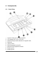
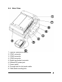
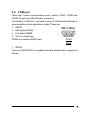
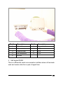
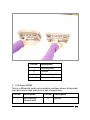
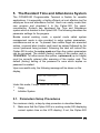
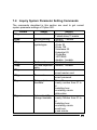
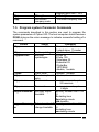
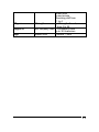
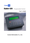
Cipher-520
Programmable Terminal
User’s Manual
Syntech Information Co., Ltd.
Table of Contents
1.
FEATURES............................................................................................. 3
2.
COMPONENTS ..................................................................................... 4
3.
4.
5.
2.1.
FRONT VIEW ............................................................................... 4
2.2.
REAR VIEW ................................................................................. 5
CHARACTERISTICS........................................................................... 6
3.1.
ELECTRICAL ............................................................................... 6
3.2.
ENVIRONMENTAL ....................................................................... 6
3.3.
P HYSICAL ................................................................................... 6
INSTALLATION.................................................................................... 7
4.1.
P OWER S OURCE.......................................................................... 7
4.2.
KEYPAD ...................................................................................... 7
4.3.
READER P ORTS ........................................................................... 7
4.4.
EXTERNAL K EYBOARD P ORT .................................................... 8
4.5.
COM PORT ................................................................................. 9
4.6.
DIGITAL INPUT / O UTPUT ......................................................... 12
4.7.
SPEAKER & EARPHONE ........................................................... 13
4.8.
WALL-MOUNT SHELF / TABLE STAND ...................................... 13
THE RESIDED TIME AND ATTENDANCE SYSTEM............... 14
5.1.
PARAMETERS S ETUP P ROCEDURES .......................................... 14
5.2.
SETUP ....................................................................................... 16
5.3.
INIT S YSTEM ............................................................................. 24
1
6.
7.
KERNEL SYSTEM ............................................................................. 25
6.1.
MEMORY M ENU ....................................................................... 25
6.2.
SET TIME .................................................................................. 25
6.3.
READER .................................................................................... 25
6.4.
P OWER ...................................................................................... 25
6.5.
TEST M ENU .............................................................................. 26
6.6.
VERSION ................................................................................... 27
RS-232 COMMANDS.......................................................................... 28
7.1.
DATA MANAGEMENT COMMANDS .......................................... 28
7.2.
INQUIRE S YSTEM PARAMETER S ETTING C OMMANDS ............ 29
7.3.
P ROGRAM SYSTEM PARAMETER C OMMANDS ......................... 30
2
1. Features
The CIPHER-520 Programmable Terminal offers outstanding features
in a compact and rugged housing suitable for office and industrial
applications alike. It can be used as a single unit or networked with up
to 32 stations and is an ideal solution for companies of all sizes. It can
be programmed in “C” or “Basic”. With its versatile programmable
features, it can be easily configured to accommodate most application
needs. Features of the Cipher-520 are listed below.
˙ TLCS-900 16 bit CPU running at 14.7456 MHz
˙ Program : 512 KB flash memory
˙ Data memory : 128 KB battery back-up SRAM
˙ Memory card : optional, 512 KB to 2 MB SRAM (in 512 KB
increments)
˙ Fine-tunable calendar chip
˙ Memory & calendar chip backup 3.6V NiCd battery
˙ Optional 1.2V x 7, 1200 or 1800 mAh rechargeable NiMH battery
pack for operation backup. 1 or 2 packs may be used.
˙ Battery/external DC voltage monitor circuit on-board
˙ Self-shutdown circuit on-board (to prevent battery over-discharge)
˙ Optional slot bar code reader or magnetic card reader
˙ 2 reader ports each for barcode scanners (Wand or
Laser-emulation), or single/dual-track magnetic card readers
˙ 240X64 graphic type LCD display with LED back-light
˙ Rubber keyboard (up to 8 X 8)
˙ Up to 16 LEDs on the keyboard board
˙ 8 digital input/output, each can be configured to input or output
˙ External keyboard port for PC/AT keyboard attachment
˙ RS232 port X 1
˙ Communication port X 2, each can be configured as CMOSRS232,
RS232, RS485 (half-duplex), RS485 (full-duplex) or 20-mA current
loop.
3
2. Components
2.1. Front View
1.
2.
3.
4.
5.
6.
7.
8.
9.
Red and Green LED for status indication
LCD display (240 X 64 or 128 X 64)
Optional slot-type reader (barcode or magnetic card)
Keyboard
Volume control
External ear-phone connector
External PC/AT keyboard connector
Reader port #1
Reader port #2
4
2.2. Rear View
1.
2.
3.
4.
5.
6.
7.
8.
9.
Optional Operational Battery
COM1 connector
COM2 connector
COM3 connector
Digital input/output connector
External DC-power jack
Power switch
Through-hole for slot reader cable
Table stand mounting hole
5
3. Characteristics
3.1. Electrical
˙ Main Power Supply Voltage : 12VDC ±5%
˙ Power consumption : 0.5W maximum with LCD backlight off and no
external devices attached
3.2. Environmental
˙ Humidity (operating) : non-condensed 20% to 90%
˙ Humidity (storage) : non-condensed 10% to 95%
˙ Temperature (operating) : 0 to 50 °C
˙ Temperature (storage)
: -20 to 70 °C
˙ EMC regulation : FCC class A and CE approved
3.3. Physical
˙ Dimensions : 261 X 125 X 100 mm (including battery holder)
˙ Weight : 1 Kg maximum including all batteries
˙ Material : ABS
˙ Color : dark-Gray
6
4. Installation
4.1. Power Source
The 520 can be powered from:
1. The external +12VDC, or
2. Operation backup battery. If line power was down, the 1200 or 1800
mAh NiMH battery pack will then provide the system power.
4.2. Keypad
An 8 by 8 scanning circuit has been reserved for accessing the built-in
rubber keyboard and LED (up to 16) indicators. The standard keyboard
provides the following keys,
˙
˙
˙
˙
˙
˙
˙
˙
˙
numbers 0~9
function keys, F1-F8 (each has a corresponding LED)
ESC, escape
clear
BS, back space
Space
Alpha, toggle between numbers and alphas (with LED)
4 direction keys (up, down, right and left)
Enter
4.3. Reader Ports
There are 2 reader ports provided, each can be either a Barcode slot
reader, Barcode Scanner (Wand/Laser emulation), or up to dual-track
magnetic card reader. They are equivalent in both hardware and
software. Their connectors and pin-assignments are listed below.
7
DB-9 Male
1 2
6
Pin Number
1
2
3
4
5
6
7
8
9
3
7
4
5
8 9
Front Veiw
Barcode
Start Of Scan
Data
Good Read
Not Used
Switch
Power Enable
Ground
Not used
Vcc, +5V
Magnetic
Not used
Clock 1
Not used
Data 1
Clock 2
Not used
Ground
Data 2
Vcc, +5V
4.4. External Keyboard Port
Besides the built-in rubber keyboard, an external PC/AT keyboard can
be attached for tedious data entry. The connector and pin assignment
conforms to PC/AT standard keyboard.
Mini-DIN 6M
5
6
3
4
1
2
Front View
Pin Number
1
2
3
4
5
6
Description
N.C.
data
+5V
Ground
N.C.
clock
8
4.5. COM port
There are 3 serial communication ports, namely COM1, COM2 and
COM3. All ports use DB-9 female connectors.
For flexibility, COM1 & 2, can have 4 kinds of COM boards attached to
accommodate various application needs. These are:
1. RS232
2. Half-duplex RS485
3. Full duplex RS485
4. 20 mA current loop
COM3 is a standard RS232 port.
DB-9 Male
1
2
6
3
7
4
8
5
9
Front
View
1. RS232
This is an EIA-RS232C compatible interface and provides 4 signals as
follows,
9
Pin No.
Description
Pin No.
Description
1
Ground
6
No connection
2
Transmit data
7
CTS
3
Receive data
8
RTS
4
No connection
9
+5V
5
ground
2. Half-duplex RS485
This is a differential serial communication interface where all terminals
send and receive data from a pair of signal lines.
10
Pin No.
Description
1
Inverting data
2
Ground
3
Non-inverting data
4-9
No connection
3. Full duplex RS485
This is a differential serial communication interface where all terminals
send and receive data each from a pair of signal lines.
Pin No.
Description
Pin No.
1
Non-inverting
transmit data
6
Description
ground
11
2
Ground
7
Inverting receive data
3
Inverting transmit
data
8
No connection
4
No connection
9
+5V
5
Non-inverting
receive data
RS485 transceivers (both half and full duplex board) are protected by a
pair of surge protectors. Also, when the terminal is at either end of the
RS485 bus, a terminator should be used to cancel signal echoing. This
can be easily done by putting the slide switch to ON position which will
connect 3 resistors onto the bus as follows,
4. 20-mA current loop
This is usually used when electrical isolation between communication
sides is required. Pin assignments of the 20-mA current loop are as
follows,
Pin No.
Description
Pin No.
Description
1
Transmit power
6
Receive cathode
2
Transmit collector
7
Ground
3
Transmit emitter
8
Ground
4
Receive power
9
+5V
5
Receive Anode
4.6. Digital Input / Output
4 digital input and 4 digital output pins has been reserved and an
optional DIO board can be used to accommodate many kinds of
input/output needs.
1. Digital Input-2 kinds of digital inputs are available,
(1) CMOS type
(2) Photo-coupled
2. Digital Output3 kinds of digital outputs are available,
12
(3) CMOS type
(4) Open-collector
(5) Relay
DB-25 Female
13 12 11 10
9
8
7
6
5
4
3
2
1
25 24 23 22 21 20 19 18 17 16 15 14
Front View
No.
1
Description
Ground
No.
23
Description
+5V
2
3-22
Ground
DIO board dependent
24
25
+5V
+5V
4.7. Speaker & Earphone
The Cipher –520 is equipped with a buzzer for audio indication. Its tone
is software controlled whereas the volume is to be tuned via a variable
resistor. Depending on application needs, an earphone can also be
attached. The audio-jack has been intentionally designed to disable
the buzzer while the earphone is connected. The usual earphone used
in Walk-Man type devices can be used with 520.
4.8. Wall-mount shelf/ Table Stand
Optional metal case or table stand can be used if mounting on the wall
or table is required.
13
5. The Resident Time and Attendance System
The CIPHER-520 Programmable Terminal is flexible for versatile
applications. It is especially, a highly efficient yet cost effective tool for
employee time and attendance control. Users can easily create their
own program and download it to the Cipher-520. For users’
convenience, Syntech has developed the Time and Attendance
system which is resident in the Cipher-520. The following describes the
parameter settings for the program.
Beside normal working mode, a special mode called system
management mode is also provided to setup system parameters,
maintenance and so on. To prevent from neither illegal nor unwanted
entries, a special label (master card) must be swiped followed by the
correct password being entered. Scanning this card will instruct the
Cipher-520 to enter the setup mode and then the system parameters
can be accessed. The default (factory) setting of the master card is
1234567890. To further secure the system, a password (up to 6 digits)
must be correctly entered after scanning of the master card. The
default (factory) setting of the password is none which implies no
password is needed.
Upon successful entry, the following message will be shown on the
display,
System Manager
1.Setup
⋅
⋅
Under this mode, 2 major tasks can be done. They are:
Setup
Initialize System
5.1. Parameters Setup Procedures
For maximum clarity, a step-by-step procedure is described below.
1.
Make sure that the Cipher-520 is in working mode (520 displaying
current system time on the LCD display). If not, the Cipher-520
14
might already be in the setup mode, press F2 key to go back to the
working mode.
Mar. 01
Mon
AM 12:00
【F1】
2.
Scan the master card. If successfully scanned with the correct
master card, the Cipher-520 will show,
PASSWORD:
3.
Now the Cipher-520 is waiting for entry of the password. However,
if the password was set to none, this message will not be shown
and this step is simply ignored. The system manager must key in
the password. To avoid side-peeking the password, the screen will
simply show "*" instead of the real password entered. Upon
completion of the password entry, press the ENTER key. Note that
neither the BACKSPACE key nor the CLEAR key are active at this
stage, the system manager must enter the right password at the
one time. If the password was not correct, the Cipher-520 will
activate a warning beep (consecutive beeps) then go back to the
working mode. If the password is correctly entered, Cipher-520
will be in the System Management mode.
System Manager
1.Setup
4.
Press the ENTER key and now the Cipher-520 is in the setup
mode and is ready to accept system parameter modification. The
Cipher-520 will show the name of parameter on the upper side of
the display and the original setting value on the lower side.
1. Line Connection:
=Master
5.
Press ENTER to change the setting value of this parameter. Use
the “<” and “>” keys to select a new setting value or type in a new
15
value via the numeric keys. Then press ENTER to conclude the
new setting value.
1. Line Connection:
-><Single>
6.
If you only want to check the parameters then simply press the “<”
or “>” keys. This will leave the setting unchanged and scroll
through the parameters. This is a handy way to simply peek at the
current settings. After all the system parameter modifications are
completed, the F1 key must be pressed to update these
modifications and save the new settings into the program memory.
The system will restart with the new settings. To abandon the
modifications and leave the settings as they were when setup was
entered press the F2 key instead of the F1 key. The modifications
will be discarded and the original settings retained.
5.2. Setup
After entering the setup mode, the user can program the setting of
each system parameter via the keypad.
The system parameters available are listed below with the parameter
number as the heading. Detailed descriptions are given and the
allowed settings are shown.
1. Line Connection Setting
Selectable values of the communication line connection parameter are
listed below.
<Master> (default value)
Reserved
Single
Slave
⋅
⋅
⋅
⋅
2. On Line Printing Setting
Selectable values of the On-line printing of the ID entries are listed
below.
<Disable> (default value)
⋅
16
⋅
Enable
3. Prefix Code Setting
⋅
⋅
Selectable values of the prefix code are listed below.
<Disable> (default value)
Enable
4. Keyboard Entry Setting
⋅
⋅
Selectable values of the keyboard entry are listed below.
< Enable > (default value)
Disable
5. Station Lock Setting
⋅
⋅
Selectable values of the station lock are listed below.
<Not Locked> (default value)
Locked
6. Station ID Setting
Acceptable values of the keyboard entry are listed below. Note that In
case of multi-station connections, care should be taken not to set more
than one station to the same station ID which will cause the RS485
communications not to work properly.
<1> (default value)
integer up to 99
⋅
⋅
7. Master Card Setting
The master card ID can be modified as needed. However, differing
from other parameter modifications, the new master card must be input
by scanning the card not by entering from the keyboard. Up to 20
characters for master card ID can be set.
<1234567890> (default value)
please scan the new master card
⋅
⋅
8. Password Setting
Up to a 6-digit password can be set to further secure the system. Note
that if a null string is entered, the password checking will be skipped
when entering setup mode. If a single ENTER key is pressed without
preceding digits, it will be treated as a null password. That is, peeking
17
only function is not available for this parameter since there is no way to
distinguish between peeking-only and a null password.
<none> (default value)
enter the new password
⋅
⋅
9. Time Setting
This is used to modify the system time of the Cipher-520. A 14-digit
value (YYYYMMDDHHNNSS) must be entered.
YYYY : total 4 digits of the year
MM : month (1 - 12)
DD : day of the month (1 - 31)
HH : hour (24 hour format, 0 - 23)
NN : minute (0 - 59)
SS : second (0 - 59)
⋅
⋅
⋅
⋅
⋅
⋅
10. Timer Fine Tune Setting
The Cipher-520 is equipped with a fine tunable calendar chip. The
speed of the calendar chip can be tuned in units of ppm via a digital
trimming register. The trimming range is from 0 to 255 ppm. The bigger
value of the trimming register the slower the calendar chip runs. For
instance, if the calendar chip is 1 second slow in one day then the
value of the trimming register should decrease 12 to correctly adjust
the calendar chip. During system initialization, this register is set to
186.
<186> (default value)
0~255
⋅
⋅
11. ID Length Setting
A 2-digit value from 0 to 99 can be set to qualify the ID entries. If set to
0, ID length will not be checked.
<0> (default value)
0~99
⋅
⋅
12 : Bar Code Symbology Setting
The Cipher-520 decoding software supports 6 types of symbology and
each symbology can be individually enabled or disabled. This option is
18
a menu level and allows access to the individual barcode settings.
Press the ENTER key to change the individual barcode type settings.
After setting the individual symbologies and returning to this menu
level the F1 key will update the memory and exit setup mode. The F2
key will abandon the changes made and restore the original settings.
Whilst in the individual barcode type setting the ENTER key will allow
the user to modify the setting. The F1 key will update memory and exit
setup mode. The F2 key will return the user to the Bar Code
Symbology Menu level.
12.1. Code 39
⋅
⋅
Selectable values for Code 39 are:
< Enable > (default value)
Disable
12.2. Code 128
⋅
⋅
Selectable values for Code 128 are:
< Enable > (default value)
Disable
12.3. Interleave 25
⋅
⋅
Selectable values for Interleave25 are:
<Enable> (default value)
Disable
12.4. Industrial 25
⋅
⋅
Selectable values for Industrial25 are:
<Enable> (default value)
Disable
12.5. Codebar
⋅
⋅
Selectable values for Codabar are:
<Enable> (default value)
Disable
19
12.6. UPC/EAN
⋅
⋅
Selectable values for UPC/EAN are:
<Enable> (default value)
Disable
13: COM1 Setting
The communication port attributes for COM1 and COM3 can be
changed individually. Press the ENTER key to change the individual
parameters. After setting the individual parameters and returning to
this menu level the F1 key will update the memory and exit setup mode.
The F2 key will abandon the changes made and restore the original
settings.
Whilst in the individual parameter setting the ENTER key will allow the
user to modify the setting. The F1 key will update memory and exit
setup mode. The F2 key will return the user to the COM1 Setting Menu
level.
13.1 COM1 BaudRate
⋅
⋅
⋅
⋅
⋅
⋅
⋅
⋅
Selectable values for COM1 baud rate are listed below.
115200
76800
57600
38400
19200
<9600> (default value)
4800
2400
13.2 COM1 Parity
⋅
⋅
⋅
Selectable values for COM1 parity are listed below.
<None> (default value)
Odd
Even
20
13.3 COM1 Data Bits
⋅
⋅
Selectable values for COM1 data bits are listed below.
<8> (default value)
7
13.4 COM1 Handshake
⋅
⋅
⋅
Selectable values for COM1 handshake are listed below.
<None> (default value)
XON/XOFF
CTS/RTS
14 : COM3 Setting
Press the ENTER key to change these settings. Whilst in the individual
parameter setting the ENTER key will allow the user to modify the
setting. The F1 key will update memory and exit setup mode. The F2
key will return the user to the COM3 Setting Menu level.
14.1 COM3 BaudRate
⋅
⋅
⋅
⋅
⋅
⋅
⋅
⋅
Selectable values for COM3 baud rate are listed below.
115200
76800
57600
38400
19200
<9600> (default value)
4800
2400
14.2 COM3 Parity
⋅
⋅
⋅
Selectable values for COM3 parity are listed below.
<none> (default value)
Odd
Even
21
14.3 COM3 Data Bits
⋅
⋅
Selectable values for COM3 data bits are listed below.
<8> (default value)
7
14.4 COM3 Handshake
⋅
⋅
⋅
Selectable values for COM3 stop bits are listed below.
<none> (default value)
XON/XOFF
CTS/RTS
15. Alarm Table Setting
After selecting this parameter, the original settings will be shown on the
display.
Whilst in the individual Alarm table setting the ENTER key will allow the
user to modify the setting. The F1 key will update memory and exit
setup mode. The F2 key will return the user to the Alarm Table Setting
Menu level.
e.g.
15.Alarm 01
=16:00 010 SEC
In the example above, the original settings of the timetable entry 01 is
16:00 for 10 seconds.
To modify this entry press the ENTER key and enter a 7 digit string
(HHMMSSS), where
HH : hour (24 hour format, 0 - 23)
MM : minute (0 - 59)
SSS : digital output duration in seconds (01 - 999, 00 if this
entry is to be ignored)
Press the “<” or “>” keys to display the next timetable entry. The
entries will cycle from 01 to 16 accordingly.
⋅
⋅
-
22
16: Workshift Table Setting
After selecting this parameter, the original settings will be shown on the
display,
Whilst in the individual Workshift table setting the ENTER key will allow
the user to modify the setting. The F1 key will update memory and exit
setup mode. The F2 key will return the user to the Workshift Table
Setting Menu level.
e.g.
16.work shift 01
=08:00-10:00 1
For the example above, the original settings of the timetable entry 01 is
08:00 to 10:00 for working shift type 1.
To modify this entry press the ENTER key and enter a 9-digit
string (HHMMhhmmW), where,
HH : hour of the starting time (24 hour format, 0 - 23)
MM : minute of the starting time (0 - 59)
hh : hour of the ending time (24 hour format, 0 - 23)
mm : minute of the ending time (0 - 59)
W : working shift type (1 to 4, 0 if this entry is to be ignored)
Press the “<” or “>” key to shift to next timetable entry. The
timetable entry will cycle from 01 to 16 accordingly.
⋅
⋅
-
17: LCD Backlight Setting
The LCD backlight can be set by this parameter. Acceptable values
are:
<on> (default value)
off
⋅
⋅
23
18: Max Station ID Setting
The station ID number can be limited by this parameter setting. To
modify this setting, enter a 2-digit number from 0 to 99.
<99> (default value)
0-99
⋅
⋅
5.3. Init System
This is used to set all system parameters to their default values and
initialize the systems files. Care should be taken, as this will destroy all
data stored in the memory.
24
6. Kernel System
Pressing the "F1", "F2" and "F3" keys simultaneously while switching
the power on, will enable the user to get into the System Menu.
6.1. Memory Menu
1. Memory Info: displays the amount of Flash, Base and card
memory.
2. Test Memory: will test the main memory and the card memory and
display s status.
3. Initialize Memory: Initialize the data memory this will clear all
memory in the Cipher520.
6.2. Set Time
Time: 1999/03/01 12:00:00
New: __/__/__ __:__:__
Set the system time, as YY/MM/DD hh:mm:ss.
6.3. Reader
Reader 1:
Reader 2:
This is used for testing the reader port. If Reader 1 or Reader 2 read
the barcode successfully, it will show as "P, Q13, 1". P is the Barcode
type; Q13 means there are 13-digits in the barcode; 1 means scanned
once.
6.4. Power
Main Power: 11.914V
Battery:
25
If Mains Power is connected the display will show the actual voltage. If
the unit is powered by batteries only it will display “main power Lost”
and show how many batteries are installed.
6.5. Test Menu
1. Buzzer: Buzzer test
2. LCD: LCD will be toggled between on and off for 15 seconds
3. LED: LED testing
4. KBD
(1) Membrane KBD testing
Each key shows on the display in reversed color. Press each
key to become normal, when all keys are pressed the user will
be returned to the KBD test menu.
(2) PC/AT KBD testing
Connect with an external keyboard and type any key for testing.
5. Digital I/O
Display the state of the digital I/O port; Ok means on, Fail means
off.
6. Communication
(1) COM1-COM3
Press ENTER, the display shows the following:
COM1 RTS…ON/OK OFF/FAIL
COM3 RTS…ON/OK OFF/FAIL
(Tests the Request To Send signal of COM1 or COM3 if it is
available)
Txmit from COM1 to COM3…OK/FAIL
Txmit from COM3 to COM1…OK/FAIL
(Tests the data transmission between COM1 and COM3)
26
(2) COM2-COM3
Similar to the above tests, using COM2 and COM3.
(3) Self Loop-Back
The display will show the interface of COM1, COM2 and COM3
when the special loop back connector is used. (refer to the
Cipher-520 Hardware Reference Manual).
6.6. Version
1. Version
2. Flash Download
Set the Baud Rate of COM3 (RS232 fixed) for the Basic/C
program or data download.
27
7. RS-232 Commands
This chapter explains how to control the Cipher-520 via the RS232 port.
Each communication transaction starts from the host side and ends
with an echoed message from the station (stand-alone, or the master
station). The carriage return (hex0d) is used as the delimiter/terminator
of each command or message. If any format error occurred, the station
would echo a NAK message.
Commands have been categorized into 3 groups according to their
functions. Their formats and usages are described below.
7.1. Data Management Commands
The commands listed in this section are used to manipulate the ID
entry data stored in Cipher-520.
Format
READ
REMOVE
CLEAR
X
Usage
Read 1 record of
data
Remove the
record just read
Initialize memory
on-line stations
inquiry
TR
System time
TWyymmddhhnn
System time
Return
OVER : buffer is empty
Kppyymmddhhnnabcq...q
where,
K:"K", identifier of 520
yymmddhhnn:date & time
a:"0"
b:working shift (1-4)
c:prefix code (0-9)
q...q:employee ID
NEW:done
OVER:buffer empty
DONE:done
aabb..pp
each 2-digits represent one
station ID
yymmddhhnn
yy:year hh:hour
mm:month nn:minute
dd:day ss:second
yy:year hh:hour
mm:month nn:minute
dd:day ss:second
28
7.2. Inquiry System Parameter Setting Commands
The commands described in this section are used to get current
system parameter settings of Cipher-520.
Format
G01pp
G03pp
G12pp
G13pp
G14pp
G18pp
G19pp
NRppnn
DRppnn
Usage
Line connection
Return
00:reserved, 10:slave
01:stand alone,11:master
On-line printing
0:disable, 1:enable
Barcode
ABCDEF
symbologies
A:Code 39
B:Code 128
C:Interleave 25
D:Industrial 25
E:Coda-Bar
F:UPC/EAN
0:disable, 1:enable
Prefix code
0:disable, 1:enable
ID code keyboard 0:disable, 1:enable
entry
Master card
nn..nn,
current master card
Password
nn..nn,
current password
Relay output
Hhmmdd
timetable
nn:entry number from 01 to
16
hh:starting hour
mm:starting minute
ddd:duration
Automatic shift
hhmmxxyyw
change timetable nn:entry number from 01 to
16
hh:starting hour
mm:starting minute
xx:end hour
yy:end minute
29
FRpp
VRpp
ID length
Get current
company code
w:working shift from 1 to 4
nn:ID length
n…n:current company code
7.3. Program system Parameter Commands
The commands described in this section are used to program the
system parameters of Cipher-520. The host computer should receive a
DONE string as the return message to indicate successful setting of a
command.
Format
S01ppnn
Usage
Line connection
Parameter
00:reserved, 10:slave
01:stand alone, 11:master
S03ppn
On-line printing
0:disable, 1:enable
S12ppABCDEF
Barcode
A:Code 39
symbologies
B:Code 128
C:Interleave 25
D:Industrial 25
E:Coda-Bar
F:UPC/EAN
0:disable, 1:enable
S13ppn
Prefix code
0:disable, 1:enable
S14ppn
ID code keyboard 0:disable, 1:enable
entry
S18ppnn..nn
Master card
nn..nn:master card, up to
20 haracters
S19ppnn..nn
Password
nn..nn : password, up to
6 digits
NWppnnhhmmdd Set relay output
Nn:entry number from 01 to
timetable
16
Hh:starting hour
Mm:starting minute
Ddd:duration
Dwppnnhhmmxxy Set automatic shift Nn:entry number from 01 to
yw
change timetable 16
hh:starting hour
mm:starting minute
30
FWppnn
VWppn…n
Lnpp
xx:end hour
yy:end minute
w:working shift from
1 to 4
ID length
nn:ID length allowed,
from 0 to 99
Set company code n…n:company code
up to 30 characters
Station lock
0:unlock, 1:lock
31