1
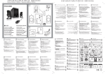
TPM
Motionnet Programming Manual
2.2.1. Dip Switches
Figure 2-3: system configuration by dip switches
Number
1
Name
TR
Description
Setting of the terminal resistance. The default settings are all off.
TR
Logic
OFF No terminal resistance added.
ON
2
ELL
Added a terminal resistance.
Setting the logic of positive and negative limits. Default values are all off.
EL
Logic
OFF When the optical coupling light is on, limit signal is on.
ON
3
TD
When the optical coupling light is on, limit signal is off.
Watchdog option
TD
Logic
OFF The LSI keeps its current status.
ON
4, 5
B0, B1
The LSI resets I/O port output and immediately stops pulse
output (stop operation).
Setting of transfer rate. Default values are all off.
B0
B1
Transfer rate
OFF OFF
20Mbps
ON
10Mbps
OFF
OFF ON
5Mbps
ON
2.5Mbps
ON
6
A4
Device number bit 4 (+16)
7, 8
M1, M2
Microstep mode
M1
M2
Microstep mode
OFF
OFF
Full step
ON
OFF
1/4 step
OFF
ON
1/16 step
ON
ON
1/32 step
18