1
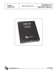
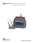
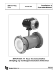
Badger®
Model 310
BadgerMeter, Inc.
Loop Powered Analog Output
Transmitter
Installation &
Operation Manual
872019
Rev. 6 4-09
Mechanical installation
The Model 310 may be surface mounted onto a panel,
attached to DIN rails using adapter clips or wall mounted using two optional enclosures.
Location
Although the Model 310 is encapsulated, all wiring
connections are made to exposed terminals. The unit
should be protected from weather and moisture in
accordance with electrical codes and standard trade
practices.
In any mounting arrangement, the primary concerns
are ease of wiring and attachment of the programming
cable.
The unit generates very little heat so no consideration
need be given to cooling or ventilation.
strips have removable plug-in connectors to make wiring easier.
1. Refer to Figure 3 for
terminal connections.
2. As shown in figure 4,
connect loop power supply
positive (+) to Model 310
terminal marked 4-20mA
loop (+).
Figure 3: Model 310 Terminal
Locations
3. Connect terminal
marked 4-20mA loop (-) of Model 310 to positive (+)
analog terminal of input device (Chart Recorder, PLC,
etc.).
4. Connect negative (-) analog terminal of input device
to loop power supply negative (-).
5. If Wiring a Series 200
sensor, connect the red
wire (signal) to Signal (+)
terminal, black wire (common) to Signal (-) terminal
and the shield to Shield
Ground terminal (Disregard
shield for the IR sensors).
Side View - Typical 300 Series Removable Connector
Figure 2: 310 Optional
Enclosure Dimensions
Surface Mount Installation
The Model 310 may be mounted to the surface of any
panel using double sided adhesive tape or by attaching
fasteners through the holes in the mounting flanges of
the unit.
DIN Rail Mounting
Optional clips snap onto the mounting flanges allowing
the Model 310 to be attached to DIN 15, 32, 35 mm DIN
rail systems.
Wall Mounting
Optional metal and plastic enclosures are available to
mount the Model 310 to a wall when no other enclosure
is used. The enclosure is first attached to the wall using
fasteners through its mounting holes.
After wiring, the transmitter may be attached to the
enclosure with the terminal headers facing in using the
slots in the mounting flanges. As an alternate mounting arrangement, the Model 310 may be fastened to the
box cover using double-sided adhesive tape.
Model 310 Electrical Installation
Per standard wiring practices, the loop power must be
off before making any wire connections. The terminal
2
Wiring
If Wiring a Series 4000 sensor, connect the clear wire
(signal) to Signal (+) terminal, black wire (common) to
Signal (-) terminal, shield wire to Shield Ground terminal, and red wire (power) to Power (4000 only) terminal.
If wiring to a sine wave output sensor consult factory.
6. For maximum EMI Protection, connect Model 310
ground lug to panel ground. See Note #1
7. Ensure that all connections are tight, then plug connector into header.
Note #1:
Included with every Model 310 is a 310IK kit containing a screw, lock washer and ground lead to connect
the Model 310 to Earth Ground. This will help prevent
electrical interference from affecting the Model 310’s
normal operation.
Figure 4: Model 310 Wiring to Analog Loop and Series 200
or Series 4000
Communications cable wiring
Field calibration requires a Data Industrial A310 Programming kit (consisting of a custom cable and software) and a PC running Windows® 9x, ME, NT, 2000
or XP. In order to program the Model 310 it must be
connected to LoopPower and the A301
cable must be connected between the
Model 310 Comm
port connector and an
available DB9 COM
Location of the
port on a computer.
DIC Communication Port
Note:
The Data Industrial A301 Cable will work with all 300
Series products. However the older version of the cable
(A300) does not have sufficient bandwidth to work with
the newer 340 Series Transmitters or SDI Flow Sensors.
3. Connect the Model 310 transmitter to a powered
4-20mA loop. (if setting up in the office a 9-24VDC
power source can be used to simulate the loop).
4. Open the interface software and select the appropriate COM PORT as shown in the dialog box below.
5. Open the Parameters Screen as shown below.
Data Industrial provides free programming software updates via the Internet for all of 300 Series devices. Go
to www.dataindustrial.com for these updates.
Programming Software Installation
Floppy Installation
Place the software installation Disk 1 into the floppy
drive and run the setup.exe program to install.
6. Program using diagram below as a reference.
CDROM Installation
Place the software CD into the CDROM drive and it
should autostart. Click programming software, then click
the Model 310 and the software installation will begin.
Web Installation
The Installation software can be found at the Data
Industrial web site (www.dataindustrial.com) in the support section.
Model 310 Programming
Programming the Model 310 is accomplished by installing the Data Industrial programming software on a computer and entering data on templates of the Windows®
based program.
1. Install the 310 PC Interface Software into the computer.
2. Connect the computer to the Model 310 transmitter using the Data Industrial A301 communications
cable. Plug A301 cable to the socket labeled “D.I.C
Comm Port” taking care to properly align the tab on the
plug and socket to maintain polarity then plug the DB9
connector of the Data Industrial A301 communications
cable to an avaliable PC com port that has the Model
310 software installed.
Note #1
Sdi - If the SDI sensor type is selected the required
K and offset values can be found the the SDI owners
manual.
4000 - If the 4000 sensor type is selected, click the
choose button and select the sensor from the pull down
box that appears.
Sine - Provided for connection to sensors which have a
sine wave output. Please consult sensor manufacturer
for the calibration settings.
200 Insert Type - If the 200 Insert Sensor type is
selected the required K and offset can be found the
the 200 owners manual or if the manual is not handy
the calculate button can be pushed and an inside pipe
diameter can be entered and once calculate is pressed
a K and offset will automatically be entered in.
200 Tee Type - If the 200 tee type is selected, click the
choose button and select the sensor from the pull down
box that appears.
3
Model 310 Specifications
Power Requirements:
Loop Input Voltage 9-35VDC
Input Frequency:
0.4 to 10 KHz
Load Resistance
Max 750Ω@24VDC
Output Response Time
Varies with filter
Temperature (operating):
-29°C to 70°C
-20°F to 158°F
Temperature (storage):
-40°C to 85°C
-40°F to 185°F
Accuracy
± 0.04% of reading over entire span
Linearity
0.1% of full scale
Warranty
Data Industrial Corporation (“Seller”) of 11 Industrial
Drive, Mattapoisett, Massachusetts 02739-0740,
U.S.A., warrants to the original purchaser of its product that such product manufactured by Data Industrial
Corporation shall be free from defects in materials or
workmanship when installed, serviced and operated
according to Data Industrial Corporation instructions or
in other such normal use. This warranty is effective for
a period of 12 months from the date of installation by
the Purchaser or 18 months from the date of shipment
by the “Seller” whichever occurs or terminates first. This
limited warranty does not cover damage or loss resulting from corrosion or erosion caused by acids or other
chemicals or by severe environmental conditions or
negligent or improper installation or improper operation,
misuse, accident, unauthorized repair or substitution of
components other than those provided by the “Seller”,
and does not cover limited life components such as
bearings, shafts, impellers where wear rate is a function
of application and environment. Any component not
manufactured by the “Seller” but included in its products
shall not be covered by this warranty and is sold only
under such warranty as the manufacturer may provide.
If Buyer or Purchaser wishes to make a claim hereunder, he shall send written notice of any defect within
the warranty period, to “Seller” at the above address.
“Seller” may at its sole option instruct Buyer to ship
subject part, postage prepaid, to the “Seller” at above
address or authorize a representative to inspect the part
on site. “Seller” will at its sole option repair or replace
any defective product covered by this warranty. If Buyer
makes repairs or alterations to any product or part
covered by this warranty without “Sellers” prior written
approval, this warranty shall be null and void.
The foregoing shall constitute Buyers or Purchasers
sole and exclusive remedy against “Seller”, and no
other remedy, including but not limited to, incidental
or consequential damages for personal injury, loss of
fluids, gases or other substances or for loss of profits
or injury to property or person shall be available to the
Buyer or Purchaser. The warranty extended herein
shall be in lieu of any other implied warranty of merchantability or fitness for a particular purpose, and seller
shall bear no liability for representatives or retail sellers.
In no event shall Data Industrial Corporation be liable
for any contingent, incidental, or consequential damage
or expenses due to partial or complete inoperability of
its product.
All rights reserved. No part of this work covered by
the copyrights hereon may be reproduced or copied
in any form or by any means - graphic, electronic, or
mechanical, including photocopying, recording, taping,
or information and retrieval systems -- without written
permission of Data Industrial.
Badger® and Data Industrial® are registered trademarks of Badger Meter, Inc.
Due to continuous research, product improvements and enhancements, Badger
Meter reserves the right to change product or system specifications without notice,
except to the extent an outstanding contractual obligation exists.
Please see our website at www.badgermeter.com
for specific contacts.
Copyright © Badger Meter, Inc. 2009. All rights reserved.
BadgerMeter, Inc.
P.O. Box 581390, Tulsa, Oklahoma 74158
(918) 836-8411 / Fax: (918) 832-9962
www.badgermeter.com