1
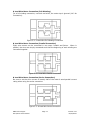
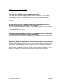
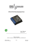
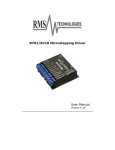
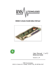
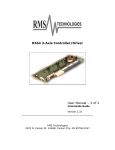
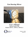
R701/R710 Microstepping Driver
User Manual
Version 6.31
RMS Technologies
2533 N. Carson St. #4698, Carson City, NV 89706-0147
RMS Technologies
R701/R710 User Manual
Page 1
Version 6.31
08/23/2010
Thank you for purchasing the R701/R710 Driver. This product is warranted to be
free of manufacturing defects for one year from the date of purchase.
Technical Support
By Telephone: 408-919-0200
(Mon.-Fri., 8:00 a.m.-5:00 p.m.)
On the Web: www.linengineering.com
Our technical support group is glad to work with you in answering your questions. If
you cannot find the solution to your particular application, or, if for any reason you
need additional technical assistance, please call technical support at 408-919-0200.
PLEASE READ BEFORE USING
Before you start, you must have a suitable step motor, a DC power supply suitable
for the motor and a current resistor. The motor’s rated phase current must be
between 1 Amps and 7 Amps, or between 0.3 Amps and 2 Amps for the low current
range. The power supply voltage must be between 4 times and 20 times the motor’s
rated voltage. The current set resistor may be a ¼ Watt, 5% part. Finally have a
STEP and DIRECTION pulse source available.
DISCLAIMER
The information provided in this document is believed to be reliable. However, no
responsibility is assumed for any possible inaccuracies or omissions. Specifications
are subject to change without notice.
RMS Technologies reserves the right to make changes without further notice to any
products herein to improve reliability, function, or design. RMS Technologies does
not assume any liability arising out of the application or use of any product or circuit
described herein; neither does it convey any license under its patent rights, nor the
rights of others.
Special Symbols
The “exclamation mark” indicates a WARNING and that this information
could prevent injury, loss of property, or even death (in extreme cases).
RMS Technologies
R701/R710 User Manual
Page 2
Version 6.31
08/23/2010
TABLE OF CONTENTS
1. FEATURES ............................................................................. 4 R701 ........................................................................................................ 4 R710 ........................................................................................................ 4 Input Option Header ................................................................................................................ 4 Multiplier Option Header........................................................................................................ 5 Figure 1: R710 Input Option and Multiplier Header.......................................................... 5 Using the Common Ground for Optos ............................................................................ 5 2. ELECTRICAL SPECIFICATIONS .............................................. 5 3. OPERATING SPECIFICATIONS .............................................. 6 Operating Temperature .......................................................................................................... 6 Heatsinking .................................................................................................................................... 6 4. MECHANICAL SPECIFICATION .............................................. 6 Dimensions .................................................................................................................................... 6 5. PIN ASSIGNMENTS ............................................................... 7 6. CONNECTION SPECIFICATIONS ............................................ 7 List of Parts ................................................................................................................................... 7 How to Connect ........................................................................................................................... 8 Table 2: Current (1 to 7 Amps)Resistor Values ................................................................. 9 Table 3: Current (0.3 to 2 Amps) Resistor Values ............................................................ 9 Figure 3: Connections Diagram ................................................................................................ 9 Resistor Values for the Opto Supply ............................................................................. 10 7. CONFIGURING AND CONTROL OF THE R701/R710 ............. 10 Adjust Trimpot ........................................................................................................................... 10 Auto Current Reduction ........................................................................................................ 10 8. MOTOR CONNECTIONS ....................................................... 12 4 Lead Wire Motor Connection ................................................................12 6 Lead Wire Motor Connection ................................................................12 8 Lead Wire Motor Connection ................................................................13 9. TROUBLESHOOTING & FAQ ................................................. 14 RMS Technologies
R701/R710 User Manual
Page 3
Version 6.31
08/23/2010
1. FEATURES
R701
• 10 microstepping driver
• Optically isolated Step, Direction, and Disable/Enable inputs
• Automatic Current Reduction
• Adjustable trimpot for noise and vibration reduction
• Operates from 24 to 80 VDC
• Selectable Driver Peak Current Ranges: 1 to 7 Amps OR 0.3 to 2 Amps
• Low Power Dissipation from 1 to 12 Watts (1 to 7 Amps)
• Excellent sinusoidal current waveform for smooth operation
• Low current ripple for low noise
• Low Cost
• High Efficiency
R710
• Built-in step pulse multiplier 1, 2, 5, and 10
• Common Ground or Common +5 Volts Input Option Available
• 10 microstepping driver
• Optically isolated Step, Direction, and Disable/Enable inputs
• Automatic Current Reduction
• Adjustable trimpot for noise and vibration reduction
• Operates from 24 to 80 VDC
• Selectable Driver Peak Current Ranges: 1 to 7 Amps OR 0.3 to 2 Amps
• Low Power Dissipation from 1 to 12 Watts (1 to 7 Amps)
• Excellent sinusoidal current waveform for smooth operation
• Low current ripple for low noise
• Low Cost
• High Efficiency
R710 OPTIONS
The R710 contains an additional board compared to the R701. This step pulse
multiplier board contains two more features that the R701 does not offer.
Input Option Header
If the R710 inputs are driven by a source where ground is only available, such as a
PC parallel port, then move the four jumpers on the header so it looks like the
“COMMON GROUND” setting in Figure 1a. Then proceed to connect the input driver
ground to Terminal 10 on the main connector.
If the R710 inputs are driven by open collector transistors or standard TTL gates,
move the four jumpers so it looks like the “COMMON +5 VDC” setting. Then proceed
to connect the input driver +5VDC in Terminal 10 on the main connector.
RMS Technologies
R701/R710 User Manual
Page 4
Version 6.31
08/23/2010
Multiplier Option Header (R710 only)
The Multiplier Option Header allows the R710 driver to always output 10
microstepping.
The benefit of this is that it allows the user to achieve 10
microstepping without having to change their original setup. Simply select the
desired step multiplier of 1, 2, 5 or 10. Figure 1b shows where the step pulse
multiplier is located on the R710 board. Use this multiplier header to select the
desired resolution. DO NOT operate the drive without a jumper.
Figure 1a
Figure 1b
Figure 1: R710 Input Option and Multiplier Header
Using the Common Ground for Optos
If you change jumpers shown in Figure 1a to allow common ground as your opto
input, the following describes how to connect the rest of your inputs.
Your negative 5V supply will connect to the “+5 VDC” line, Pin 10. The negative side
of your step pulses should then connect to your “Step” line, Pin 9. The positive side
of your +5V and the positive side of your step pulses should be tied together.
To disable the drive, connect the disable pin to Pin 12, the end of the current set
resistor pin. To change direction of rotation, connect the direction pin to the +5V
and + step pulse connection.
2. ELECTRICAL SPECIFICATIONS
Supply Voltage: +24 to 80 VDC
Peak Current: 1 to 7 Amps OR 0.3 to 2 Amps
Auto Current Reduction: 33% of set current, 1 second after last Step Pulse
Quiescent Current: 15 mAmps or less
Resolution: 10 microstepping
RMS Technologies
R701/R710 User Manual
Page 5
Version 6.31
08/23/2010
3. OPERATING SPECIFICATIONS
Step frequency: 0 to 200 kHz
Step Pulse Time on falling edge (0): 0.5 microseconds (µS) minimum
Step Pulse Time on rising edge (1): 4.0 µS minimum
Direction Setup: 1 µS minimum (20 µS minimum hold time after Step edge)
Operating Temperature: 0° to 70° Celsius
Humidity Range: 0 to 95% (non-condensing)
Power Dissipation: 1 to 12 Watts (1 to 7 Amps)
Heatsinking
The R701/R710 needs an additional heatsink for current settings greater than 3
Amps. The case temperature (measured from the bottom plate) should not exceed
70° C. For best results, use heatsink compound between the R701/R710 and the
heatsink.
4. MECHANICAL SPECIFICATIONS
Size: 2.5” x 2.5” x 0.826” (63.5 mm x 63.5 mm x 21.0 mm)
Weight: 3.6 oz (100 gm)
Mounting: Four #6-32 screws, 1.75” x 2.372” (44.5 mm x 60.2 mm)
Cover: Aluminum, Anodized
Plate: Aluminum, Hard Anodized
Color: Black exterior, Blue or White Text
Dimensions
Figure 2: Dimensions Diagram
RMS Technologies
R701/R710 User Manual
Page 6
Version 6.31
08/23/2010
5. PIN ASSIGNMENTS
PIN #
1
2
3
4
5
6
7
8
9
10
11
12
FUNCTION
Power Ground
+V
Phase A
Phase APhase B
Phase BEnable/Disable
Input
Direction Input
DESCRIPTION
The ground or return of power supply connects here.
Motor Supply Voltage. +24 to +80 VDC
A of the stepping motor
A- of the stepping motor
B of the stepping motor
B- of the stepping motor
Used to ground to the logic functions (i.e. step
pulses or direction)
This input is used to change the rotation direction of
the motor
Step Clock
Negative (falling) going edge on this input advances
the motor one increment. The size of the increment
is depending on the image set.
Opto Supply
+5 VDC input used to supply power to the isolated
logic inputs. A resistor must be used if the supply is
greater than 5 VDC.
Current Set
Connects to the open-collector drive.
Current Set
Connects to the open-collector drive.
Table 1: Pin Assignments
6. CONNECTION SPECIFICATIONS
List of Parts
Connection of the R701/R710 is simple. Here is what you need:
• External Main Power Supply (+24 to +80 VDC)
• +5 VDC Power Supply used as the Opto Supply (See Table 2)
• A Function Generator
• An appropriate Bipolar Stepper Motor
WARNING! Power supply voltage in excess of +80 VDC will
damage the R701/R710. Do not short the motor leads to each
other or to ground. This will also damage the board.
WARNING! Do not shut off the power while the motor is
moving, this could result in a catastrophic failure of the drive.
RMS Technologies
R701/R710 User Manual
Page 7
Version 6.31
08/23/2010
How to Connect
For safety reasons, please connect the power supply (Terminal 2) last.
Terminal 1: Power Ground - Connect the power supply ground here.
Terminal 2: +24 to 80 VDC - Connect the positive (+) end of the power supply
here.
The maximum power supply current required is 67% of the motor’s rated phase
current. An unregulated power supply may be used as long as the voltage stays
between the limits; keep the ripple voltage to 10% or less for best results.
If the power supply is more than 1 foot (300 mm) away from the driver, a 470 µF
capacitor must be connected across the R701/R710’s power supply terminals. Keep
the capacitor lead length to 1 inch (25 mm) or less. Note: If using multiple drives
daisy chained on a single power supply you will need a capacitor for each drive.
The choice of power supply voltage depends on the high speed performance required
of the motor. Doubling the voltage doubles the motor’s high speed power. In all
cases the power supply voltage should be no less than 4 times or no more than 25
times the motor’s rated voltage. The motor may not run as smoothly as possible if it
is too low, and the board may be damaged if it is run too high.
_
Terminal 3: Phase A
Terminal 4: Phase A
_
Terminal 5: Phase B
Terminal 6: Phase B
Connect one motor winding to terminals 3 & 4. Connect the other winding to
terminals 5 & 6. Turn the power supply off when connecting or disconnecting the
motor. If the motor turns in the wrong direction, reverse the motor windings for
terminal 3 & 4. Please see the “8. Motor Connections” section for connecting 4, 6, or
8 wire motors.
Terminal 7: Disable – Short this pin to filter ground (pin 12, end of current set
resistor slot) to disable the unit. Shorting it to this ground forces winding currents to
zero and stops all output switching activity. The R701 will continue totalizing step
and direction inputs if any are sent. The power supply current drops to less than
15mAmps. The motor will return to its original position when the disable input is
released if no step pulses have been sent and the motor has not been moved more
than 20 microsteps (2 full steps).
Terminal 8: Direction Input - Closing this connection to signal ground will change
the direction of the rotating motor
Terminal 9: Step Input - Connect the positive (+) terminal of the function
generator to this terminal. If you have an alternative pulse generator, connect it to
this terminal.
Terminal 10: +5VDC - Connect the positive (+) end of the external +5 V Power
supply to this terminal. Then connect the negative (-) of this power supply to the
negative (-) of the pulse generator. The two negative connections are considered
signal ground.
RMS Technologies
R701/R710 User Manual
Page 8
Version 6.31
08/23/2010
These inputs are optically isolated from the rest of the drive. Terminal 10 is the
common anode connection for the opto-isolators and must be connected to the +5
VDC supply of your indexer or pulse generator.
These inputs are meant to be driven by standard TTL logic or other driver capable of
sinking 16 mA of current. The minimum logic “0” time is .5 usec while the minimum
logic “1” time is 4 usec. Microstepping occurs on the falling edge of the step input.
Terminal 11: Current Set - Connect one end of the resistor to this terminal.
Terminal 12: Current Set - Connect the other end of the resistor to this terminal.
This terminal is a filter ground.
Resistor Values to set the Current
Please use the corresponding resistor for the correct current setting for your motor.
If you are using the driver with currents of 1 to 7 Amps, R = 47*I/(7-I).
If you are using the driver with currents of 0.3 to 2 Amps, R = 47*I/(2-I).
(R = Resistor in kΩ)
Current (Amps)
Resistor Value
(Ohms 5%)
1
8200
2
18000
3
36000
4
62000
5
120000
6
270000
7
Open
Table 2: Current (1 to 7 Amps) Resistor Values
Current (Amps)
Resistor Value
(Ohms 5%)
0.3
8200
0.5
15000
1.0
47000
1.5
130000
2.0
Open
Table 3: Current (0.3 to 2 Amps) Resistor Values
Figure 3: Connections Diagram
RMS Technologies
R701/R710 User Manual
Page 9
Version 6.31
08/23/2010
Resistor Values for the Opto Supply
The optocouplers must be powered by an external power supply to maintain
isolation. The Opto Supply (Terminal 10) for the optocouplers can be between +5 to
24 VDC with respect to the signal input. It is recommended to use a +5 VDC Opto
Supply in order to limit the current going into the optocouplers to 16 mA. However,
if the supply is greater than +5 VDC then a resistor must be connected in series with
the STEP line and another one in series with the DIRECTION line to maintain 16 mA
of current running through the optocouplers. Refer to Table 4 for the corresponding
Resistor Values.
The Resistor shall be put in series with the Positive Terminal of the Opto Supply and with
Terminal 8 (Direction) and Terminal 9 (Step).
Opto Supply
Resistor Value
(Ohms 5%)
5V
10 V
330 Ohm, 1/8 Watt
15 V
680 Ohm, 1/4 Watt
20 V
1.0K Ohm, 1/4 Watt
24 V
1.2K Ohm, 1/2 Watt
Table 4: Opto Supply Resistor Values
7. CONFIGURING AND CONTROL OF THE R701/R710
Adjust Trimpot
This trimpot adjusts the motor for the smoothest possible low speed operation. Set
the motor speed to about ¼ revolutions per second, and then, using a flathead
screwdriver turn the trimpot until a distinct null is noted in the motor’s vibration.
This will result in the most even microstep placement for a given motor and power
supply voltage. The trimpot is located on the opposite side of main connector on the
driver.
Auto Current Reduction
The R701/R710 reduces motor phase current to 33% of the set value when the
motor is holding. To disable this feature remove the cover and adjust jumper JP1
(see Figure 4). Choices for hold current are 33% or 100% of the set run current.
RMS Technologies
R701/R710 User Manual
Page 10
Version 6.31
08/23/2010
Reduced Current Range
By not placing any jumpers in positions 1, 2, 5 or 6, the R701 will operate over a
reduced current range (0.3A to 2.0A). This should be used when using motors rated
at 1 Amp or less. Holding current is at 100% of the run current during this setting.
Mid-Band Compensation
Some step pulse sources generate very “ragged” timing. If the pulse-to-pulse period
varies by more than +/- 30%, at the default jumper setting at 7 & 8, the drive may
have problems counting that step pulse. By disabling the mid-band option and
placing the jumper across 4 & 8, this will make the driver insensitive to this timing
restriction. But, as a result, the motor might exhibit mid-band instability problems
(also known as resonance).
5
12 3 4
5
8
1 to 7 Amps
33% hold current
(default)
1 to 7 Amps
100% hold current
0.3 to 2 Amps
100% hold current
Midband compensation
(default)
Midband Disabled
5 6 7 8
Figure 4: Standard Current Disable
Note: The jumper options for jumper positions 1, 2, 5 & 6 are options for run and
hold current capabilities. The jumper options for position 4, 5, 7, & 8 are for the
mid-band or normal setting.
RMS Technologies
R701/R710 User Manual
Page 11
Version 6.31
08/23/2010
Main Connector
The R701/R710 uses a 2-piece modular main connector. The connector is split into
two pieces: Terminals 1 through 6 (power supply and motor leads) and Terminals 7
through 12 (control interface). Each can be removed separately by pulling the
connector body upwards and off of the mating header pins on the R710. You may
need to remove the connectors to mount the R701/R710 properly to a chassis.
8. MOTOR CONNECTIONS
Step Motors have 4, 6, or 8 wires. To better understand how to connect your step
motor with your R701/R710 Driver, follow the Figures below for the corresponding
motor. NOTE: The dots indicate the starting position of the wires when wound.
4 Lead Wire Motor Connection
Connect one set of windings to the A terminals. Connect the other set of windings to
the B terminals. If the set of windings is unclear, take a pair of wires; use an
ohmmeter to check for continuity. When you find the first two wires that have
continuity, connect it to the A terminals. Connect the other two to the B terminals.
Figure 5.1: 4 Lead Wire Motor Connection
6 Lead Wire Motor Connection (Half Winding)
Six wire motors can be wound in two ways: Half Winding and Full Winding. Six wire
motors contain a center tap on each of the two windings. For a half-winding
connection, the center tap and one end of the wires are used.
Figure 5.2: 6 Lead Wire Half Winding Connection
RMS Technologies
R701/R710 User Manual
Page 12
Version 6.31
08/23/2010
6 Lead Wire Motor Connection (Full-Winding)
For a full winding connection, use both end wires, the center tap is ignored. (NC: No
Connection).
Figure 5.3: 6 Lead Wire Full Winding Connection
8 Lead Wire Motor Connection (Parallel Connection)
Eight wire motors can be connected in two ways: Parallel and Series. When in
parallel, the wires are simply connected such that the beginning of each winding are
connected together.
Figure 5.4: 8 Lead Wire Parallel Connection
8 Lead Wire Motor Connection (Series Connection)
Be sure to set the drive current to exactly half of the motor’s rated parallel current
rating when using the series connection.
Figure 5.5: 8 Lead Wire Series Connection
RMS Technologies
R701/R710 User Manual
Page 13
Version 6.31
08/23/2010
9. Troubleshooting & FAQ
The Motor is in Holding Position, but does not rotate:
This means that Power is being supplied to the driver and motor, so the power
supply is OK. However, the signal generator might be causing the problem. Try
changing the signal to TTL. If this doesn't help, is the external +5 VDC Power
connected? Be sure that the step pulses are a 0 to 5V squarewave with even on and
off time.
My step motor requires 0.95 amp/phase, which setting should I use 1-7
amp or 0.3-2 amp? Can I use the 1-7 amp setting?
It is not recommended that you use the 1-7 Amp setting given that your motors are
rated at 0.95 amp/phase. We always recommend that the user use the
recommended current or lower.
I did the resistor calculation, but there is no standard resistor at that value.
Is it better to use the higher or lower value resistor?
We recommend that you use the resistor that will give you the lower current output
to be on the safe side.
What is the difference between the blue terminal connectors versus the new
green terminal connectors?
Physically, the difference between the blue versus green connectors is that the blue
ones require a flat heat screw driver to screw wires into the terminals. The green
connectors require a Phillips screw driver. The blue connectors became unavailable
and therefore we changed over to the Phoenix connectors which are green in color.
During this transition, there were black connectors used as well, temporarily.
RMS Technologies
R701/R710 User Manual
Page 14
Version 6.31
08/23/2010