1
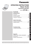
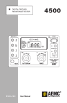
GPS-12R & GPS-12RG
GPS & GLONASS/GPS
Frequency Standards
User’s Manual
4031 600 12001
Rev. 03 October 2008
This manual, in whole or in part, may not be copied without permission of the copyright owner.
All product names are trademarks of their respective companies.
© 2008 Pendulum Instruments AB
All rights reserved
Printed in Sweden
II
Table of Contents
GENERAL INFORMATION . . . . . . . . . . . . IV
5 Preventive Maintenance
1 Preface
Calibration . . . . . . . . . . . . . . . . . . . . . . . . 5-2
Fan Replacement . . . . . . . . . . . . . . . . . . . 5-3
Battery Replacement . . . . . . . . . . . . . . . . 5-3
Introduction . . . . . . . . . . . . . . . . . . 1-2
2 Preparation for Use
6 Specifications
Safety Instructions . . . . . . . . . . . . . 2-2
Technical Specification . . . . . . . . . 6-2
Introduction . . . . . . . . . . . . . . . . . . . . . . . . 2-2
Safety Precautions . . . . . . . . . . . . . . . . . . 2-2
Frequency Stability . . . . . . . . . . . . . . . . . . 6-2
Ordering Information . . . . . . . . . . . . . . . . . 6-6
Unpacking . . . . . . . . . . . . . . . . . . . . 2-3
Unpacking Instructions . . . . . . . . . . . . . . . 2-3
7 Appendix
Installation . . . . . . . . . . . . . . . . . . . 2-4
Antenna Installation . . . . . . . . . . . . . . . . . 7-2
Supply Voltage . . . . . . . . . . . . . . . . . . . . . 2-4
Power Switch . . . . . . . . . . . . . . . . . . . . . . 2-4
Orientation and Cooling . . . . . . . . . . . . . . 2-5
Fold-down Support . . . . . . . . . . . . . . . . . . 2-5
Rackmount Adapter . . . . . . . . . . . . . . . . . 2-5
Antenna Installation . . . . . . . . . . . . . . . . . 2-7
Connecting to a PC . . . . . . . . . . . . . . . . . 2-7
8 Index
Disposal of Hazardous Material . . 2-8
3 Using the Controls
Front Panel . . . . . . . . . . . . . . . . . . . . . . . . 3-2
Rear Panel . . . . . . . . . . . . . . . . . . . . . . . . 3-3
Functional Description . . . . . . . . . . . . . . . 3-4
User Interface . . . . . . . . . . . . . . . . . . . . . . 3-4
4 Performance Check
General Information . . . . . . . . . . . . . . . . . 4-2
Preparations . . . . . . . . . . . . . . . . . . . . . . . 4-2
Front Panel Controls . . . . . . . . . . . . . . . . . 4-3
Front Panel Outputs . . . . . . . . . . . . . . . . . 4-3
Rear Panel Outputs . . . . . . . . . . . . . . . . . 4-3
III
9 Service
Sales and Service Office . . . . . . . . . . . . . 9-II
GENERAL INFORMATION
Warranty
The Warranty Statement is part of the folder Important Information that is included with the
shipment.
Declaration of Conformity
The complete text with formal statements concerning product identification, manufacturer and
standards used for type testing is available on request.
Convention of Notation
Most information in this manual is common to the GPS-12R and the GPS-12RG. When the type
number is used as a reference to both of them, the designation GPS-12R(G) has been chosen. Otherwise the device is referred to with its proper type number, i.e. either GPS-12R or GPS-12RG.
Figures illustrating the menu screens depict the GPS-12R, when the differences are small and
self-explanatory. Where necessary, additional figures for the GPS-12RG have been included.
Terms in the text referring to the GPS-12RG only are placed in brackets.
IV
Chapter 1
Preface
Preface
Introduction
Cesium-controlled
Frequency via Satellites
Optional Outputs
The GPS-controlled frequency standard
GPS-12R and the GLONASS/GPS-controlled
frequency standard GPS-12RG deliver a precision frequency and time reference everywhere
in the world. They gain their long-term frequency stability from Cesium standards in the
navigation satellite systems GPS and
GLONASS. They are also designed to provide
very high short-term stability and are cost-efficient and extremely accurate frequency
standards.
These reference sources are very suitable as frequency standards in the telecommunication and
electronics industry. They fit both as stationary
frequency references - for instance in test systems and as local references in the design department - and as portable, highly accurate reference
sources for field use.
These instruments are off-air frequency standards with an internal architecture according to
Figure 1-1. They have one antenna input and a
number of optional frequency outputs.
The GPS-12R(G) (rubidium atomic clocks)
come as standard with two 2.048/1.544 MHz
square wave outputs and one 1 PPS pulse output with approx. 10 µs duration. The
GPS-12RG has also 3 x 10 MHz and 1 x 5 MHz
outputs. See Option 70B below. There are five
options to choose from, options 70B, 71B, 72B,
73B and 74B. They allow for four extra frequency outputs to be mounted. Any combination of none, one or two of these units is possible.
Option 70B gives 3 x 10 MHz and 1 x 5 MHz
sine wave outputs, 1 VRMS in 50 W. The
GPS-12RG is as standard equipped with one
such option.
Option 71B gives four 1VRMS in 50 W sine
wave outputs of resp. 10 MHz, 5 MHz, 1 MHz
and 0.1 MHz.
Option 72B gives two 2.048 MHz clock outputs, ±1.2 V square wave in 75 W, + two
2.048 Mbps data outputs (G.703:10), for telecommunication testing and clock synchronization.
Option 73B gives 4 x 13 MHz square wave outputs with TTL levels in 50 W.
Option 74B gives two 1.544 MHz +
two 1.544 Mbps outputs for SONET
applications.
Satellite
Receiver
Figure 1-1
1-2
Phase
Comparator
Local
Oscillator
(VCO)
Refererence Out
Simplified block diagram of the
GPS-12R(G).
Two Operating Modes
The disciplined mode is the default
mode. It eliminates long-term frequency drift, also called aging. As
Preface
long as there is a valid satellite signal, the local
rubidium oscillator is continuously adjusted to
minimize the deviation from the satellite-derived reference signal.
The hold-over mode is entered either automatically, if the satellite contact is lost, or manually.
The automatic adjustment is replaced by the
normal aging characteristics of the rubidium
oscillator.
The manual hold-over mode is mainly intended
for the hopefully rare occasions when the satellite contact is sporadic, causing unacceptable
mode switching interference.
tions. AC line voltage and -48 VDC can be applied at the same time in order to realize a true
uninterruptible power supply (UPS).
Overall Accuracy
The cesium standards of the satellites are controlled by primary frequency standards like the
US Naval Observatory, and ultimately to all national standards (e.g. NIST, NPL, PTB, SP
etc.).
Portability
By means of Option 78, an internal rechargeable battery unit, it is possible to maintain stability during transportation, as the internal reference oscillator is continuously powered.
Field use without access to AC line power is
also practicable.
This option has the additional feature of accepting an external 12 VDC supply. Thus it is possible to realize a true uninterruptible power supply (UPS), as the DC source and the AC source
can be applied simultaneously. The AC source
takes precedence, as long as it is present, and so
does the external DC supply over the internal
battery, which is kept charged by one of the external sources.
In case of a power line failure you will benefit
from double security, if you utilize an external
DC source in addition to the AC supply.
Stationary Use
Option 77 makes it possible to apply -48 VDC
as an alternative to the standard AC line voltage, thus allowing permanent use as local frequency standard in telephone exchange sta-
1-3
Preface
This page is intentionally left blank.
1-4
Chapter 2
Preparation for Use
Preparation for Use
Safety Instructions
Introduction
Read this chapter carefully before you install
and use the instrument.
This instrument has been designed and tested
for Measurement Category I, Pollution Degree
2, in accordance with EN/IEC 61010-1:2001
and CAN/CSA-C22.2 No. 61010-1-04 (including approval). It has been supplied in a safe
condition. The user of this instrument must
have sufficient knowledge of it. This knowledge can be gained by thoroughly studying this
manual, especially the sections on Safety Precautions and Installation in this chapter.
This instrument is designed to be used by
trained personnel only. Removal of the cover
for repair or rack-mounting of the instrument
must be done by qualified personnel who are
aware of the hazards involved. There are no
user-serviceable parts inside the instrument.
Safety Precautions
All equipment that can be connected to line
power is a potential danger to life. Handling restrictions imposed on such equipment should
be observed.
To ensure the correct and safe operation of this
instrument, it is essential that you follow generally accepted safety procedures in addition to
the safety precautions specified in this manual.
The warranty commitments are rendered
void if unauthorized access to the interior of
the instrument has taken place during the
given warranty period.
2-2 Introduction
Caution and Warning
Statements
CAUTION: Shows where incorrect
procedures can cause damage to,
or destruction of equipment or
other property.
WARNING: Shows a potential danger
that requires correct procedures or
practices to prevent personal injury.
Symbols
Shows where the protective ground
terminal is connected inside the instrument. Never remove or loosen this
screw.
This symbol is used for identifying the
functional ground of an I/O signal. It is
always connected to the instrument
chassis.
Indicates that the operator should consult the manual.
If in Doubt about Safety
Whenever you suspect that it is unsafe to use
the instrument, you must make it inoperative by
doing as follows:
– Disconnect the line cord.
– Clearly mark the instrument to prevent its
further operation.
– Inform your local Pendulum Service Center.
For example, the instrument is likely to be unsafe if it is visibly damaged.
Preparation for Use
Unpacking
Unpacking
Instructions
– Certificate of Calibration.
Identification
Check that the shipment is complete and that no
damage has occurred during transportation. If
the contents are incomplete or damaged, file a
claim with the carrier immediately. Also notify
your local Pendulum sales or service office in
case repair or replacement may be required.
Options installed inside the cover are identified
on the rear panel according to the list below. Up
to two output boards in any combination can be
fitted at the same time.
Check List
Option 71B: 4 BNC-connectors mounted in the
area designated.
The shipment should contain the following:
– The frequency standard.
– A line cord.
– A CD with PDF manuals for Pendulum
products, e.g. this manual.
– If you ordered one or two of the output
options (70B, 71B, 72B, 73B, 74B), or
one of the DC supply options (77, 78),
they should already be installed. See
“Identification” below.
Note: The GPS-12RG is as standard
equipped with one Option 70B.
– If you ordered one of the DC supply options (77, 78), a three-pole power D-sub
socket connector is included that mates
with the corresponding rear panel pin connector. It is intended for making a wire
harness suitable for linking the instrument
to an external DC power source.
Option 70B: 4 BNC-connectors mounted in the
area designated.
Option 72B: 4 BNC-connectors mounted in the
area designated.
Option 73B: 4 BNC-connectors mounted in the
area designated.
Option 74B: 4 BNC-connectors mounted in the
area designated.
Option 77: -48 VDC power supply & rear panel
power D-sub connector.
Option 78: Internal 16 VDC rechargeable battery & rear panel power D-sub connector for
ext. 12 VDC source.
– Other options you ordered, e.g. antenna
(option 01), antenna cable (option 02),
rack mount kit (option 22) or carrying
case (option 27/27H) are shipped in separate boxes.
2-3 Unpacking Instructions
Preparation for Use
Installation
Supply Voltage
Setting
The GPS-12R(G) frequency standard may be
connected to any AC supply with a voltage rating of 90 to 265 Vrms , 45 to 440 Hz. The frequency standard automatically adjusts itself to
the input line voltage.
Depending on option chosen, the unit can also
be supplied by external DC sources, -48 V or
+12 V.
Fuse
The secondary supply voltages are electronically protected against overload or short circuit. The primary line voltage side is protected
by a fuse located on the power supply unit. The
fuse rating covers the full voltage range. Consequently there is no need for the user to replace the fuse under any operating conditions,
nor is it accessible from the outside.
CAUTION: If this fuse is blown, it is
likely that the power supply is
badly damaged. do not replace the
fuse. Send the frequency standard
to the local Pendulum Service Center.
Grounding
Grounding faults in the line voltage
supply will make any instrument connected to it dangerous. Before connecting any unit to the power line, you must
make sure that the protective ground functions
2-4 Supply Voltage
correctly. Only then can a unit be connected to
the power line and only by using a three-wire
line cord. No other method of grounding is permitted. Extension cords must always have a
protective ground conductor.
WARNING: If a unit is moved from a
cold to a warm environment, condensation may cause a shock
hazard. Ensure, therefore, that the
grounding requirements are strictly
met.
WARNING: Never interrupt the
grounding cord. Any interruption
of the protective ground connection inside or outside the
instrument or disconnection of the
protective ground terminal is likely
to make the instrument dangerous.
Power Switch
This instrument is equipped with a secondary
power switch. It disconnects the main
power-consuming circuits on the secondary
side of the power supply but leaves the rubidium oscillator active in order to retain its
long-term characteristics. Line voltage is always present on the primary side.
WARNING: Always consider the instrument active as soon as it is
connected to the primary AC
power source with a power cord.
Preparation for Use
Orientation and
Cooling
The frequency standard can be operated in any
position desired. Make sure the air flow
through the ventilation slots are not obstructed.
Leave 50 mm (2 in) of space around the
instrument.
CAUTION: Never cover the ventilation slots at the right or left side. If
the slots are covered, the frequency standard will overheat.
Fan Control
The speed-controlled fan is used for adjusting
the temperature inside the frequency standard
to compensate for variations in ambient temperature.
Fold-down Support
For bench-top use, a fold-down support is
available for use underneath the frequency
standard. This support can also be used as a
handle to carry the instrument.
Figure 2-2
Rackmount
Adapter
Figure 2-3
Figure 2-1
Air flow through the
GPS-12R(G).
Fold-down support for comfortable bench-top use.
Dimensions for rackmounting
hardware.
If you have ordered a 19 inch rack mount kit for
your instrument, it has to be assembled after delivery of the instrument. The rack mount kit
consists of the following:
2 brackets, (short, left; long, right)
4 screws, M5 x 8
4 screws, M6 x 8
WARNING: When you remove the
cover you will expose live parts
and accessible terminals which
can cause death.
2-5 Orientation and Cooling
Preparation for Use
WARNING: Capacitors inside the instrument can hold their charge
even if the instrument has been
separated from all voltage sources.
Figure 2-6
– Remove the four feet from the cover.
Use a screwdriver as shown in the following illustration or a pair of pliers to remove the
springs holding each foot, then push out the
feet.
Fitting the rackmount brackets
on the counter.
Assembling the Rackmount
Kit
– Make sure the power cord is disconnected
from the instrument.
– Turn the instrument upside down.
See Figure 2-4.
– Undo the two screws (A) and remove
them from the cover.
– Remove the rear feet by undoing the two
screws (B).
– Remove the four decorative plugs (C) that
cover the screw holes on the right and left
side of the front panel.
– Grip the front panel and gently push at the
rear.
– Pull the instrument out of the cover.
Figure 2-5
Removing the feet from the
cover.
– Push the instrument back into the cover.
See Figure 2-4.
– Mount the two rear feet with the screws
(B) to the rear panel.
– Put the two screws (A) back.
– Fasten the brackets at the left and right
side with the screws included as illustrated
in Figure 2-6.
– Fasten the instrument in the rack via
screws in the four rack-mounting holes
The long bracket has an opening so that cables
for Input A, B, and C can be routed inside the
rack.
n Reversing the Rackmount Kit
The instrument may also be mounted to the
right in the rack. To do so, swap the position of
the two brackets.
Figure 2-4
Remove the screws and push
the frequency standard out of
the cover.
2-6 Rackmount Adapter
Preparation for Use
Antenna
Installation
The antenna (option 01), is intended for outdoor mounting on a wall or preferably on a
roof. The more free sky that is visible from the
antenna’s position, the better the satellite contact. There is an antenna mounting kit (Option
01/50) available for this purpose.
The antenna cable is a 20 meter (option 02) or
50 m (option 02/50) high quality RG213 cable
that connects at one end to the antenna and at
the other end to the rear panel of the frequency
standard. For installation details and instructions on connecting other antennas/cables than
those supplied by Pendulum, please consult the
Appendix in this manual.
Connecting to a PC
A PC can be connected to the USB port at the
rear of the instrument for firmware download.
A suitable cable should have one USB-A connector (for the PC) and one USB-B connector
-for the GPS-12R(G).
The procedure is described in the service manual, as only trained personnel should do FW upgrades. Erroneous handling of the instrument
before and during the download may damage
the memory contents and prohibit the completion of the loading process.
2-7 Antenna Installation
Preparation for Use
Disposal of Hazardous Material
The basic instrument and all optional units except Option 78 have no batteries or other parts
containing hazardous amounts of substances
that require special attention or handling instructions.
Option 78 contains a rechargeable NiMH battery pack that serves the purpose of providing
uninterruptible power to the instrument. As all
batteries, it has a finite lifetime. Although
NiMH-based cells are by far less detrimental to
the environment than their NiCd-based predecessors, we strongly recommend to dispose of
them by controlled recycling.
CAUTION: Make sure the battery
pack is recycled according to local
regulations.
2-8 Connecting to a PC
Chapter 3
Using the Controls
Front Panel
LCD display with backlight forming the
User Interface (UI) together with the
CURSOR and ENTER keys to the right.
The default messages inform the user about
Control Mode (Disciplined or Hold-over),
Satellite Status, Alarm, Power Source, User
Options and Time/Position.
GPS-12R
The CURSOR keys (with arrow symbols)
are used for moving the cursor, marked by
text inversion, around the menus on the
display. By pressing the ENTER key you
either confirm a choice or enter a submenu.
Back one step by pressing the LEFT ARROW key.
RUBIDIUM FREQUENCY STANDARD
ENTER
2.048 MHz OUT
±1.2V IN 75W
POWER ON / STANDBY
key. A secondary power
switch that ligths up the red
LED above the key in standby
mode.
!
1 PPS OUTPUT
TTL !
BNC Reference Output Connectors
2 x 2.048 MHz + 1 x 1 PPS or
2 x 1.544 MHz + 1 x 1 PPS
The choice is made in the
User Options submenu.
Optional outputs can be found on the
rear panel.
3-2 Front Panel
Using the Controls
Rear Panel
Antenna cable input
(N-contact)
GPS ANTENNA IN
Fan with automatic
speed control
Optional
external DC
power inputs
Power input
90-265 V,
45-440 Hz
!
:
2.048 MHz OUT
2.048 MHz OUT
2.048 Mbps OUT
!
!
2.048 Mbps OUT
!
!
USB
2.048 MHz OUT
2.048 MHz OUT
!
2.048 Mbps OUT
!
ALARM
+12VDC
GND
-48VDC
2.048 Mbps OUT
!
!
191125
Optional Outputs
Option 70B: sine wave
3 x 10 MHz + 1 x 5 MHz
Option 71B: sine wave
1 x 10 MHz + 1 x 5 MHz + 1 x 1 MHz +
1 x 0.1 MHz
Option 72B: square wave
2 x 2.048 MHz +2 x 2.048 Mbps
USB port for firmware download
from PC
;
Two relay-controlled alarm
loops, one for
urgent and one
for non-urgent
situations.
See page 3-6
for pin configuration.
Option 73B: square wave 4 x 13 MHz
Option 74B: square wave
2 x 1.544 MHz + 2 x 1.544 Mbps
3-3 Rear Panel
Using the Controls
Functional
Description
– Hold-over mode (free-running local oscil-
The GPS-12R(G) is a frequency standard that is
continuously disciplined by control signals
from satellites belonging to the GPS
(GPS-12R) or GLONASS+GPS (GPS-12RG)
navigation satellite systems. The signals have
very low long-term uncertainty (5*10-13 per
24h), and are traceable to different national
standards for time and frequency at, for instance, the National Institute of Standards and
Technology (NIST) via the US Naval Office
(USNO). The GPS-12R(G) contains a satellite
receiver module, generating a stable 1 pps signal, plus a local voltage-controlled rubidium
oscillator and a high resolution measurement
kernel that is continuously phase-comparing
the received satellite signal and the local oscillator. This means that the local oscillator is continuously monitored and adjusted.
Disciplined mode is the default mode.
Hold-over mode is automatically entered when
the disciplining fails for some reason (e.g. loss
of satellite contact). Hold-over mode can also
be forced via the User Interface (UI). When the
satellite contact is lost, the GPS-12R(G) can not
be continuously controlled (intercompared
with the satellite reference clocks in real time)
and reverts temporarily to hold-over mode
specifications.
lator)
– Disciplined mode (monitored and adjusted
local oscillators)
The GPS-12R(G) can operate in two different
modes. Either the local oscillator is free-running with a frequency offset that increases with
time, due to aging, or the results of the phase
comparisons are used for adjusting the local oscillator, thereby compensating for aging. These
two modes are called:
User Interface
General Principles
The UI is straightforward. All interaction between operator and instrument takes place by
navigating a cursor (marked by text inversion)
on the LCD through a set of text-based menus.
The navigating tools are just four arrow keys,
UP ( p ), DOWN ( q ), LEFT ( t ),
RIGHT ( u ), and one ENTER key. The different menus are described in the following paragraphs.
Default Menu
Satellite
Receiver
1 PPS
PLL-Controlled
Frequency Reference Oscillator
(Rubidium or OCXO)
1 PPS Output
2.048 MHz Outputs
Output Opt.
Microprocessor
&
Memory
User Interface (UI)
(Front Panel Keyboard & Display)
Figure 3-1.
Other Frequencies
Output Opt.
To PC (USB)
The internal high-stability oscillator of the
GPS-12R(G) is continuously compared
with and controlled by the satellite receiver.
3-4 Functional Description
This is the menu entered at start-up
and shows the current instrument status. Here RB-osc is selected, and to
the right you can find one of the following short informative texts:
•
•
•
•
Warming up
Unlocked
Hold-over
Manual Hold-over
Using the Controls
•
Disciplined by GPS [GNSS]
n 1 PPS
Here you can set the time offset of the 1 PPS
output signal that is available on the front
panel. The range is ±999 ns.
GPS [GNSS] Menu
Note: GNSS stands for Global Navigational
Satellite System and refers to either
GPS or GLONASS.
The normal end message after the transitory
start-up phase, which usually lasts less than 20
minutes, is Disciplined by GPS [GNSS]. Then
we assume that the antenna installation has
been performed according to given instructions.
Rb Oscillator Menu
By pressing u you will enter the Rb-osc
submenu, indicated by the corresponding label
at the top left corner:
Moving the cursor to GPS [GNSS] in the default menu will bring you to the GPS [GNSS]
submenu.
Here you can see your current position and how
many satellites that you are locked to. You can
also adjust the antenna delay. The GPS-12RG
has three operational modes. See the screen below that appears when you enter the Mode
menu. Select the mode that gives the best performance at your location.
n Mode
Here you can change the operational mode of
the oscillator. If you want to return to the default menu, press t. By pressing ENTER or u
you will be able to select the mode. Use p or
q, and confirm your choice by returning to the
previous screen. Press t.
If you want to see a list of all locked satellites
and their status you should move the cursor to
Locked to and then press ENTER or u. The
menu below will be activated.
n Antenna Delay
In order to compensate for the signal delay introduced by the antenna and its connecting cable, the 1-pps reference signal from the GPS receiver can be shifted in time from this menu. If
3-5 User Interface
Using the Controls
you don’t know the exact delay, assume an
approximate value of 5 ns/m as a rule of thumb.
Alarm Menu
In this menu you can watch and manage the
alarm log. You can also set up the alarm behavior.
n Alarm Outputs
Two relay-controlled alarm loops, one for urgent and one for non-urgent situations, are
available via a D-sub connector on the rear
panel. The normally closed (NC) contacts will
open when the respective alarm criteria are
met. Figure 3-2 shows the pin configuration.
ALARM LEVEL
URGENT
NON-URGENT
Scroll through the log entries by selecting Log.
Then press ENTER or u.
Figure 3-2
CIRCUIT (NC)
Pins 8-9
Pins 1-6
Alarm connector pin
configuration.
Power Source Menu
If you press ENTER or u once more, you are
given the opportunity to erase the log entries.
In this menu you can see what power options
are installed and the current status of those options.
Note:
In the alarm Setup menu you can choose among
a number of alarm sources and decide their
alarm level, i.e. urgent, non-urgent, or no
alarm.
When the unit is about to enter
Standby mode, and the battery option is installed, the screen below will
appear.
Only one of the alternative DC power supply
units, Option 77 or Option 78, can be installed.
Both can serve as UPS devices, i.e. you can
have external (Option 77) or internal (Option
78) battery backup for the AC supply. Both
units allow external DC voltage feed instead of
the standard AC line power feed.
3-6 User Interface
Using the Controls
User Options
From this submenu you can configure miscellaneous settings and obtain important data on the
instrument and its options.
Note: The sign q at the bottom left corner indicates that additional information
can be displayed by scrolling.
n Language
The instrument UI is prepared for different language modules that can be downloaded over
the USB port. The standard module comprises
the following languages:
•
•
•
•
•
•
•
•
•
•
•
DD-MM-YYYY
DD/MM/YYYY
DD-MM-YY
DD/MM/YY
MM/DD/YYYY
n Time Zone
Here you can enter the local time zone to adjust
the clock display.
n Front Panel Outputs
Switch between 2.048 MHz and 1.544 MHz.
n About
Information about the instrument, e.g. installed
options and firmware version.
English
German
French
Spanish
Turkish
Russian
There is also a module available containing
Chinese and Japanese. English can always be
chosen, irrespective of the active language
module.
n Display Contrast
The adjustment range is 0-100 %. The optimum
value depends on the angle of view from which
the display is observed.
n Time Format
The following formats are currently available:
•
•
•
•
YYYY-MM-DD
YYYY/MM/DD
YY-MM-DD
YY/MM/DD
3-7 User Interface
Using the Controls
This page is intentionally left blank.
3-8 User Interface
Chapter 4
Performance Check
Performance Check
General
Information
WARNING: Before turning on the instrument, ensure that it has been
installed in accordance with the Installation Instructions outlined in
Chapter 1 of the User’s Manual.
This performance procedure is intended for incoming inspection to determine the acceptability of newly purchased instruments, or whenever a quick test is convenient.
Note:
described in Chapter 5, Preventive Maintenance.
Preparations
Connect the antenna, including cable, to the antenna input (rear). Make sure the antenna position is satisfactory.
Power-On Test
Connect the AC power cord to the instrument
and the line power outlet. The instrument shall
automatically enter Operating mode, indicated
by the following characteristics:
The procedure does not check every
facet of the instrument. It is concerned primarily with those parts of
the instrument which are essential for
determining the function of the instrument.
This GPS- [GNSS-] controlled Frequency Reference does not need to
be sent away for frequency calibration. The instrument is continuously
monitored and adjusted by means of
the GPS [GNSS] signal, as long as
there is sufficient satellite contact,
and the active operating mode is not
Hold-over.
The display backlight shall be lit.
The default screen shall be visible.
« Note the message Warming Up
on the first line.
• The Standby LED shall not be lit.
• The fan shall start.
Wait until the instrument shows the messages
Disciplined by GPS [GNSS] and Locked to X
satellites, where X>2. It will normally take less
than 20 minutes.
It is not necessary to remove the instrument
cover to perform this procedure.
Press the Power/Standby key to see if the instrument enters Standby mode, indicated by the
following characteristics:
Note:
Recommended Test
Equipment
– DSO with 50 W input
– Pendulum CNT-90 timer/counter
– A calibrated 1, 5 or 10 MHz reference
source with at least rubidium characteristics.
The GPS-controlled Pendulum GPS-89 or
Fluke 910R is a suitable choice, as it can
also be used for the calibration procedure
4-2 General Information
•
•
•
•
•
•
The red Standby LED shall be lit.
The display shall go out.
The fan shall stop.
The rubidium oscillator is still powered.
The state of the rubidium oscillator can not be
observed directly, but when you power up the
instrument again to proceed with the performance check, you can see from the accompanying display message that the Warming Up phase
is very short. Consequently the startup process
will be accelerated accordingly.
Performance Check
Power up your instrument at least 30 minutes
before continuing. This will allow the instrument to reach normal operating temperature
and go into Disciplined by GPS [GNSS] mode
with adequate margins.
Front Panel
Controls
– Connect a DSO with 75 W inputs to both
the 2.048 / 1.544 MHz outputs, one at a
time.
– Verify that the signal is a square wave,
and that the low level is -1.2 V ± 10 %
and the high level +1.2 V ± 10 %.
– Connect the counter and verify that the
frequency is:
2.048 / 1.544 MHz ± 0.002 Hz.
Keyboard Test
1 pps
1 Make sure the default menu is visible. See
Connect a DSO with 50 W inputs to the 1 pps
output. Verify that the signal is a rectangular
pulse train with a pulse width of approx. 10 µs,
and that the low level is <0.9V and the high
level >1.8V. Connect the counter and verify
that the frequency is 1Hz ± 1 µHz.
page 3-4. Check that the cursor (marked by
text inversion) can be moved upwards and
downwards with the UP/DOWN arrows,
and that you can enter submenus with the
RIGHT ARROW key and return from the
submenu with the LEFT ARROW key.
2 Select Rb-osc and press ENTER twice.
Rear Panel Outputs
Make sure you see the screen below:
Option 70B
(3 x 10 MHz & 1 x 5 MHz)
3 Return to the default menu by pressing the
LEFT ARROW key twice.
Front Panel
Outputs
Connect the reference frequency source to the
EXT REF input on the rear panel of the CNT-90
counter and recall the default settings.
2.048 / 1.544 MHz
Select 2.048 MHz via User Options and follow
the test directions below. Then select
1.544 MHz and repeat the test:
Connect a DSO with 50 W inputs to all BNC
connectors, one at a time. Verify that the four
output signals are sinusoidal and that the voltage is at least 1 Vrms. Connect the counter and
verify that the frequency is 10 MHz ± 0.01 Hz
resp. 5 MHz ± 0.005 Hz.
Option 71B
(0.1 & 1 & 5 & 10 MHz)
Connect a DSO with 50 W inputs to all BNC
connectors, one at a time. Verify that the four
output signals are sinusoidal and that the voltage is at least 1Vrms. Connect the counter and
verify that the frequency is 10 MHz ± 0.01 Hz,
5 MHz ± 0.005 Hz, 1 MHz ± 0.001 Hz and 0.1
MHz ± 0.0001 Hz respectively.
4-3 Front Panel Controls
Performance Check
Option 72B
Option 74B
(2 x 2.048 MHz & 2 x 2.048 Mbps)
(2 x 1.544 MHz + 2 x 1.544 Mbps)
Connect a DSO with 75 W inputs to all BNC
connectors, one at a time. Verify that the output
signal is a rectangular pulse train with an amplitude of ±1.2 V ± 0.12V. Connect the counter
and verify that the frequency at the two clock
outputs is 2.048 MHz ± 0.002 Hz. The amplitude at the two data outputs can be checked in
the same way. For a quick check of the validity
of the encoded HDB-3 data, do like this:
Connect a DSO with 75 W inputs to all BNC
connectors, one at a time. Verify that the output
signal is a rectangular pulse train with an amplitude of ±1.2 V ± 0.12V. Connect the counter
and verify that the frequency at the two clock
outputs is 1.544 MHz ± 0.0015 Hz. The amplitude at the two data outputs can be checked in
the same way. For a quick check of the validity
of the encoded HDB-3 data, do like this:
– Connect the data outputs, one at a time, to
– Connect the data outputs, one at a time, to
Input A on the counter and measure according to the procedure below.
Input A on the counter and measure according to the procedure below.
– Recall the default settings and make these
– Recall the default settings and make these
alterations in the INPUT A menu:
alterations in the INPUT A menu:
– DC coupling
– 50 W input impedance
– Trig 75 %
– DC coupling
– 50 W input impedance
– Trig 75 %
– Select MEAS FUNC ®Period ®
– Select MEAS FUNC ®Period ®
– Select STATistics.
– Select STATistics.
The result should be the clock period time multiplied by four, i.e. 4 x 488 = 1952 ± 2 ns
Standard Deviation s < 1 ns
The result should be the clock period time multiplied by four, i.e. 4 x 648 = 2592 ± 2 ns
Standard Deviation s < 1 ns
Option 73B
Option 77
(4 x 13 MHz)
(-48 VDC from ext. source)
– Disconnect the line power cord.
– Connect 48 VDC to the power D-sub con-
Single ® A
Connect a DSO with 50 W inputs to all BNC
connectors, one at a time. Verify that the signal
is a square wave, and that the low level is
<0.9 V and the high level >1.8 V. Connect the
counter and verify that the frequency is
13 MHz ± 0.013 Hz.
Single ® A
nector with the plus pole to the ground pin
and the minus pole to the pin marked
-48VDC. Use the mating D-sub socket
connector that is included with the
instrument.
– Check that the instrument behaves in the
same way as when it is connected to line
power only.
4-4 Rear Panel Outputs
Performance Check
– Reconnect the line power cord, and disconnect the 48 V source temporarily.
– Check that the instrument behaves normally.
– Reconnect the 48 V source while the instrument is still operating off line power.
– Check that the instrument behaves normally.
– Disconnect the line power cord and check
that the instrument continues to work
without interruption (UPS function).
– Disconnect the 12 V source.
– Check that the instrument continues to
work without interruption (UPS function).
– Reconnect the line power cord.
– Check that the instrument behaves normally.
– Let the internal battery charge for about
half an hour.
– Disconnect the line power cord and check
that the instrument continues to work
without interruption (UPS function).
Option 78
Alarm Output
(Int. battery backup & ext. 12 VDC)
– Connect the instrument to line power and
– Make sure the instrument is in Standby
press the Power/Standby button to enter
Standby mode. The red LED above the
button shall light up.
– Let the internal battery charge for 3 hours.
Then it will reach about 80 % of its capacity.
Note: It will take another 21 hours for the battery to reach full capacity if it was completely
discharged from the beginning.
– Disconnect the power cord and switch on
the instrument.
– Check that the instrument behaves normally and is operative for about 90 minutes.
– Connect 12 VDC to the power D-sub con-
Mode.
– Measure the resistance between pin 8 and
pin 9 on the D-SUB alarm connector.
Expected result: open circuit (near infinity)
– Measure the resistance between pin 1 and
pin 6 on the D-SUB alarm connector.
Expected result: open circuit (near infinity)
– Switch on the instrument.
– Measure the resistance between pin 8 and
pin 9 on the D-SUB alarm connector.
Expected result: closed circuit (near zero)
– Measure the resistance between pin 1 and
pin 6 on the D-SUB alarm connector.
Expected result: closed circuit (near zero)
nector with the minus pole to the ground
pin and the plus pole to the pin marked
+12VDC. Use the mating D-sub socket
connector that is included with the instrument.
– Check that the instrument behaves in the
same way as when it is connected to line
power only.
– Let the internal battery charge for about
half an hour.
4-5 Rear Panel Outputs
Performance Check
This page is intentionally left blank.
4-6 Rear Panel Outputs
Chapter 5
Preventive
Maintenance
Preventive Maintenance
Calibration
Calibration and adjustment in the traditional
sense are not necessary as long as the instrument is operating in GPS-[GNSS-]disciplined
mode. Then the internal rubidium timebase is
continuously monitored and forced to follow
the cesium clocks of the navigational satellites.
These clocks are traceable to, for instance,
NIST and USNO. Thus the normal aging characteristics of the internal timebase will be concealed.
However, if the device is operating in hold-over
mode for long periods, the aging characteristics
are no longer concealed. Then you may need to
reset the timebase from time to time by letting
the device operate in disciplined mode for at
least 48 hours. See also next paragraph.
n Calibration Intervals
Normally it is quite adequate to check the frequency deviation between one of the reference
outputs and a corresponding, independent, cesium-controlled reference source once a year,
using the procedure described below. Shorter
intervals may be necessary if the main operating mode is hold-over, and the allowed deviation is less than the specified annual aging. See
the timebase specifications to collect the data
for these calculations.
n Equipment
– The DUT (Device Under Test).
– Timer/Counter Pendulum CNT-90.
– A GPS-controlled reference frequency
source capable of generating both 2.048
MHz and alternatively 1, 5 or 10 MHz at
an amplitude between 0.1 and 5 Vrms in
50 W. It should also have a traceable calibration history. The Pendulum GPS-89
with Option 72 is apt to the task.
– BNC cables of suitable lenghts.
5-2 Calibration
Note:
There are several ways to perform
this checkup, depending on available
equipment. The setup and procedure
described in the next paragraphs are
based on the list above.
n Setup
– Connect the reference source (1, 5 or
10 MHz) to the EXT REF input on the
counter.
– Connect one of the 2.048 MHz outputs on
the front panel of the DUT to Input A on
the counter.
– Connect the 2.048 MHz reference source
to Input B on the counter.
– Find a good antenna position, and connect
the antenna to the DUT. Power up the
DUT and the reference source at least 24
hours before starting the verification procedure. Make sure the GPS contact is established and the system is working within
15 minutes after the DUT was switched
on.
– Power up the timer/counter at least one
hour before starting the verification procedure.
n Procedure
Note:
Each key depression is not described
here. See the Operators Manual for
the timer/counter if you need more
information.
– Recall the default settings of the counter.
– Set the trigger level to Man 0.0 V on both
Input A and Input B.
– Set the measuring time to 10 s.
– Check that the frequency is 2.048 MHz ±
0.01 Hz.
– Change measurement function to Time Interval A to B.
Preventive Maintenance
– Set Number of Samples to 2, Pacing Time
to 100 s and Pacing to ON in the SETTINGS menu.
– Select STAT (statistics) and HOLD.
– Press RESTART.
– Wait for the measurement to finish after
100 s (marked by HOLD appearing at
the upper right corner of the display).
Check that Max and Min are both positive. Otherwise press RESTART again to
repeat the measurement.
– Note the P-P value that equals the absolute difference between the maximum and
the minimum time interval error value
(DTIE), and calculate the equivalent relative frequency deviation
Df = DTIE / 100.
Acceptance criterion
Df calculated according to the expression above
should be less than 2 x 10-12.
– Change the DUT mode to Manual
Hold-over.
– Press RESTART and note the intermediate
result for sample #1, i.e. before the measurement ends after 100 s.
– Wait 24 h.
– Press RESTART and note the intermediate
Fan Replacement
If your frequency reference is operating
24h/day, you need to replace the fan every 5
years to maintain high reliability. For part-time
applications and low ambient temperatures, an
extended service interval is acceptable.
Fan replacement requires no special tools
(screwdrivers only). The part number of the replacement fan is 4031 105 02850.
Battery
Replacement
There are no batteries in the basic instrument.
Option 78 has a NiMH battery pack that is specially adapted to its purpose. It must not be replaced by anything else but the original part,
the order number of which is 4031 100 67190.
Replacement is recommended when the battery
operating time falls short of one hour, provided
the battery pack has been charged in standby
mode for at least 24 hours.
Dispose of the old battery pack according to local recycling regulations. See also page 2-8.
result for sample #1, i.e. before the measurement ends after 100 s.
– Calculate the absolute difference between
the two results (DTIE).
– Calculate Df = DTIE / 86400.
Acceptance criterion
Df calculated according to the expression above
should be less than 5 x 10-12.
5-3 Fan Replacement
Preventive Maintenance
This page is intentionally left blank.
5-4 Battery Replacement
Chapter 6
Specifications
Specifications
Technical Specification
Frequency Stability
Disciplined by GPS [GNSS]
Standard Reference Outputs
Allan dev. @ 20-26 °C:
(t = 24 h)
(t = 100 s)
(t = 10 s)
(t = 1 s)
Connector
3 x BNC on the front panel
type:
Frequency #1: 2 x 2.048 MHz alt.
2 x 1.544 MHz
Square wave ±1.2 V ± 10 %
Output level:
in 75 W (G.703:10)
Freq. stability: See frequency stability specs
for GPS-locked respectively
hold-over modes.
<0.01 UI
Jitter:
Frequency #2: 1 x 1 pps
approx. 0 V … 5 V unloaded
Output level:
approx. 0 V … 2.0 V in 50 W
Approx. 10 µs (GPS-locked)
Pulse width:
Freq. stability: See frequency stability specs
for GPS-locked respectively
hold-over modes
Jitter
(GPS-locked): <1 ns rms relative to UTC or
GPS (position hold)
Hold-over
approx. 1 ms drift after
accuracy:
1 day of Hold-over
Phase noise:
Warm-up time
to lock at +25 °C:
<2×10-12
<5×10-12
<1.7×10⁻¹¹
<5×10-11
-140 dBc/Hz
@ 10 kHz offset
<7 min to 1x10⁻⁹
Hold-Over
Aging/month:
Temp. (0 °C...+50 °C):
6-2 Frequency Stability
<5×10-11
<1×10⁻¹⁰
Specifications
Alarm Outputs
Option 72B Outputs
Connector
type:
Connector
type:
Frequencies:
Signal coding:
9-p male D-Sub, 1 loop for
urgent alarm, 1 loop for
non-urgent alarm
relay open ® alarm mode
relay closed ® normal mode
Max. switching
60 VDC
voltage:
Max. switching
200 mA
current:
Option 70B Outputs*
Connector
type:
Frequencies:
Output level:
Freq. stability:
2.048 MHz
Output level:
Square wave ±1.2 V ± 10 %
in 75W (G.703:10)
Freq. stability: See frequency stability specs
for GPS-[GNSS-]locked
resp. hold-over modes.
<0.01 UI
Jitter:
(G.703)
2.048 Mbps:
Option 73B Outputs
BNC
3 x 10 MHz + 1 x 5 MHz
Sine wave >1 VRMS in 50 W
See frequency stability specs
for GPS-[GNSS-]locked
resp. hold-over modes.
(GPS-12R only)
Connector
type:
Frequencies:
Output level:
Freq. stability:
Option 71B Outputs
Jitter:
Connector
type:
Frequencies:
Output level:
Freq. stability:
BNC
2 x 2.048 MHz +
2 x 2.048 Mbps
BNC
4 x 13 MHz
Square wave TTL in 50 W
See frequency stability specs
for GPS-[GNSS-]locked
resp. hold-over modes.
<0.01 UI
BNC
10, 5, 1 and 0.1 MHz
Sine wave >1 VRMS in 50 W
See frequency stability specs
for GPS-[GNSS-]locked
resp. hold-over modes.
*Note: The GPS-12RG is as standard
equipped with one Option 70B.
6-3 Frequency Stability
Specifications
Option 74B Outputs
Connector
type:
Frequencies:
BNC
2 x 1.544 MHz +
2 x 1.544 Mbps
1.544 MHz
Output level:
Square wave ±1.2 V ± 10%
in 75W (G.703:10)
Freq. stability: See frequency stability specs
for GPS-[GNSS-]locked
resp. hold-over modes.
<0.01 UI
Jitter:
(G.703)
1.544 Mbps:
Option 77 (GPS-12R only)
n External DC Supply (-48 VDC)
Connector
type:
Voltage:
3-pin power D-sub
-48 VDC ± 10 %
Option 78
** In standby mode only the rubidium timebase
oscillator is active in order to save power and
resume full operability with minimum delay after transportation.
Controls
User Interface: LCD supported by 4 cursor
keys and 1 ENTER key
Power:
Secondary STBY key
LED Indicator
Standby
Mode:
Power ON
Mode:
Red LED above the key is
ON
Red LED above the key is
OFF
GPS Receiver
Trimble
IRZ
Resolution-T (GPS-12R)
MNP-M3 (GPS-12RG)
n Internal Backup Battery
Battery type:
Connector
type:*
Ext. Supply:
On/Standby
time:**
NiMH, 16.8 V, 2.3 Ah
Antenna
connector:
Power out:
3-pin power D-sub
+12 VDC ± 10 %
³2 h
*An external 12 VDC source can charge the internal battery as well as power the instrument in
normal mode. The battery is also being charged
when the instrument is connected to AC line
power.
6-4 Frequency Stability
Channels
Trimble:
IRZ:
Carrier, code:
Type N
+5 V, 0.1 A on center
conductor for feeding
active antenna and line
amplifiers
12, parallel tracking
16, parallel tracking
L1, C/A
Specifications
Antenna (Option 01/00)
Fan
Internal with temperature-controlled speed.
Type:
Operating temperature:
Height:
Weight:
Gain:
Connector:
active GPS only, L1 band
Environmental Data
-40°C to +70°C
81 mm (3.2”)
230 g (8 oz.)
>30 dB
TNC
Temperature:
Humidity:
Altitude:
Antenna (Option 01/90)
Vibration:
Type:
Operating temperature:
Dimensions:
Gain:
Connector:
active, combined
GLONASS/GPS L1 band
-40°C to +85°C
100 x 45 mm
>30 dB
TNC
Shock:
Safety:
EMI:
Antenna Cable (Option 02)
Type:
Length:
Connectors:
Attenuation:
Cable delay:
RG213
20 m, 50 m & 130 m
type N and TNC (male)
approx.
0.4 dB/m @ 1.6 GHz
approx. 5.05 ns/m
PC Connection
Interface:
Connector:
Purpose:
USB 1.1
USB, type B, female
Firmware loading
0°C...+50°C (operating)
-40°C...+70°C (storage)
95% RH, 0°C..+30°C
(operating & storage)
<4600 m (operating)
<12000 m (storage)
3G @ 55 Hz per
MIL-T-28800D, Class 3,
Style D
Half-sine 40G per
MIL-T-28800D, Class 3,
Style D. Bench handling.
Compliant with CE:
EN 61010-1 2:nd edition,
Cat II, Pollution degree 2
Compliant with CE:
EN61326-1 (1997)
Dimensions and Weight
WxHxD:
Weight:
210 x 108 x 395 mm
Net 3.1 kg (6.6 lbs), shipping 4.1 kg (8.8 lbs)
(excl. batteries)
Power Consumption
Line voltage:
90...264 V
Line frequency: 45...440 Hz
Power:
<75W at warm-up
<35W continuous operation
6-5 Frequency Stability
Specifications
Ordering
Information
GPS-12R:
2 x 2.048 / 1.544 MHz
1 x 1 pps standard outputs
GPS-12RG: 2 x 2.048 / 1.544 MHz
1 x 1 pps
3 x 10 MHz + 1 x 5 MHz
standard outputs
Opt. 70B:* 3 x 10 MHz + 1 x 5 MHz
outputs
Opt. 71B: 0.1 + 1 + 5 + 10 MHz outputs
Opt. 72B: 2 x 2.048 MHz +
2 x 2.048 Mbps outputs
Opt. 73B:** 4 x 13 MHz outputs
2 x 1.544 MHz +
Opt 74B:
2 x 1.544 Mbps outputs
Opt 77:** -48 V external DC supply
Internal battery backup w. exOpt 78:
ternal DC connector for charging and continuous operation
None of the options above is retrofittable,
which means that they must be ordered for factory installation together with the basic unit.
Up to two of the options designated 7XB can be
fitted at the same time in any combination, e.g.
2 x Option 70B or Option 71B + Option 74B.
Included Accessories
Users Manual in PDF on CD
Calibration certificate
18 months warranty
6-6 Ordering Information
Optional Accessories
19” rack mount kit
Soft carrying case
Heavy duty hard transport
case
Option 01/00: GPS only antenna
Option 01/90: GLONASS/GPS antenna
Option 01/50: Antenna mounting kit
Antenna cable, 20 m
Option 02:
Option 02/50: Antenna cable, 50 m
Option 02/130: Antenna cable, 130 m
Option 90/10: Calibration certificate
with protocol
Option 90/00: Calibration certificate
Hold-over aging/week
Option 95/03: Extended warranty 3 years
Option 95/05: Extended warranty 5 years
Option OM-12: Printed Users Manual (PDF
file included as standard)
Option 22/90:
Option 27:
Option 27H:
Notes: * standard in the GPS-12RG
** for the GPS-12R only
Chapter 7
Appendix
Appendix
Antenna
Installation
Introduction
When installing an antenna for the satellite controlled frequency standards GPS-12R(G), some
basic facts should be considered, relating to antennas and radio reception properties. The theoretical and practical discussions below will
help you to make the right decisions.
Pendulum supplies satellite antennas and an antenna mounting kit as well as cable assemblies
of different lengths. Other system components
that may be necessary to meet your requirements are readily available from vendors of
GPS/ GLONASS antenna equipment.
It is important to observe that deviations from
the recommended normal solution may severely impair the performance of the overall
system, unless the user has acquired the knowledge necessary to design a configuration of his
own. General guidelines to good system design
are given in this section of the handbook, but
the user is entirely responsible for adequate
performance in this case.
Available Options for
Antenna Installation
Option 01/00: GPS antenna w. Type TNC
fem. connector
Option 01/90: GLONASS/GPS antenna w.
Type TNC fem. connector
Option 01/50: Antenna mounting kit for wall
or pole mounting.
Option 02:
Antenna cable, 20 m (Opt.
02/20), 50 m (Opt. 02/50) and,
130 m (Opt. 02/130) with Type
TNC male connector at one
end and Type N male at the
other.
General Guidelines to Good
Antenna Location
The general rule that applies to all installations
working in or near the microwave frequency
bands is that it should be possible to see the
transmitter from the receiver antenna position.
When dealing with terrestrial radio communication it is a great advantage to place both the
transmitter antenna and the receiver antenna as
high as possible. The effective line-of-sight distance increases with the square root of the
height above ground.
The satellite-based transmitters are, however,
moving targets in the sky and require in part
new rules of thumb. Moreover, you need at
least see more than two satellites simultaneously, irrespective of the point of time, to get
stable time readings. The receiver can have
contact with 12 GPS or 16 GLONASS satellites
at the same time, but in practice three is enough
for timing purposes, when the receiver is stationary.
It is not certain that an elevated location is an
advantage, unless it is the only way to see as
much of the sky as possible including the horizon in most directions. On the contrary, location on the ground could be more efficient from
a technical point of view if you do not have to
consider certain negative factors like the risk of
physical damage and the influence of snow and
ice on the antenna efficiency.
Other conditions to be taken into account are
multi-path reception and interference from
high-frequency signal sources nearby. All these
7-2 Antenna Installation
Appendix
considerations could force you to find a place for
the antenna situated far from the receiver and
high above ground level. We will discuss these
matters presently, but the implication in brief is
that new system components may have to be introduced, like low-loss coaxial cables and line
amplifiers.
Coping with Interference
There are mainly two sources of interference
that may affect the location of the antenna.
They will be treated below. Careful inspection
of the proposed site can often reveal the most
apparent ones.
n Multi-path Reception
Reflections from metal surfaces nearby can
cause the wanted signal to enter the antenna
from two or more directions with more or less
equal strength. Then the phase relationship determines whether the resulting signal will be
amplified or attenuated. At worst it can vanish.
Since the GPS/GLONASS satellites are not stationary the conditions can be compared to the
fading problem on the shortwave bands. The
directive sensitivity of the antenna resembles a
hemisphere with its base plane going horizontally through the antenna, provided it is
mounted vertically on top of a mast. Therefore
you must avoid locations near reflective surfaces beside or above the antenna.
n High-frequency Interference
Strong signal sources in the vicinity, like cellular radio transmitters, can cause interference or
saturation in the antenna amplifier. Even
though the systems do not operate at the same
frequency the problem has still been observed
from time to time and must not be neglected.
Standard Configuration
The majority of installations can do with the
standard configuration, consisting of one
satellite antenna, one 20-m antenna cable, and
the frequency
reference itself, the
GPS-12R(G). In many cases, the distance between the antenna and the receiver could be less
than 20 m. Normally excessive cable length is
easy to tolerate. Do not shorten the cable, unless absolutely necessary, because the high antenna gain of 36 dB requires the signal to be attenuated by at least 6 dB before entering the receiver.
Deviations from the Standard
Configuration
n General Principles
The system configurations that cannot directly
use the standard options provided by Pendulum
can be listed in different ways. One simple
method of classification used here is to isolate a
number of cases and treat them separately. If
several steps have to be taken to arrive at a solution that satisfies all requirements, then it
should be possible to derive the individual
components from the list by means of combination. The method is illustrated by some practical examples later in this chapter.
The most important design parameter is the cable loss at the receiving frequency. There are a
number of cable types to choose from, but for
the sake of simplicity one normal and one
low-loss type have been selected:
Cable type
Attenuation per 100 m
Standard (RG-213)
Low loss (LMR400)
Approx 40 dB
Approx 17 dB
7-3 Antenna Installation
Appendix
The common laboratory cable RG-58 has been
excluded, as its losses only allow relatively
short distances between antenna and receiver. It
is more flexible, however, and might be utilized
with care, if you are fully aware of its characteristics.
Remaining parameters to consider are:
Antenna gain:
Guard band:
Total external gain at
the receiver input:
+36 dB (option 01)
±3 dB
+11dB … +33 dB
When designing your own antenna installation,
you must check that the gain at the receiver input is within limits according to the above table. That is, you must check that:
+ antenna gain
- total attenuation
+ total amplification
- guard band
+ antenna gain
- total attenuation
+ total amplification
+ guard band
³ +11 dB
£ +33 dB
n Case Classification
The distance between antenna and
receiver exceeds 20 m but not 55 m
– Use a coaxial cable of type RG-213 or
cascade two or three pieces of option 02
by means of adapters. Note that normal
adapters are not weatherproof and should
be placed indoors. Normally there is little
to gain by using a low-loss cable in this
case, but see example #1 below. RG-213 is
more inexpensive and flexible.
The distance between antenna and
receiver exceeds 55 m but not 130 m
– Use a low-loss coaxial cable of type LMR
400 or equivalent.
7-4 Antenna Installation
The distance between antenna and
receiver exceeds 130 m but not 245 m
– Use a line amplifier with a nominal gain
of 20 dB plus low-loss coaxial cable of
type LMR 400 or equivalent. The amplifier must accept a fixed +5 V supply voltage fed through the central conductor of
the coaxial cable. The maximum input
power for linear operation should be at
least –6 dBm, and the noise figure should
be less than 2 dB.
The distance between antenna and
receiver is in the range 245-360 m
– Use two cascaded line amplifiers (20 dB
each) plus low-loss coaxial cable of type
LMR 400 or equivalent.
Better protection against lightning
strikes needed
Lightning protection is a wide field and cannot
be covered more than superficially in this manual. If the building is situated in a risk area, a
general survey of the overall house protection
might be needed. Especially lightning rods near
the GPS antenna mounting mast should be inspected. Make sure that the antenna is far from
being the highest point and, as a precaution,
ground the mounting mast as if it were part of
the ordinary lightning rod system.
There are several conditions that may call for a
separate lightning arrester to support the
built-in antenna protection.
– The cable length outside the building exceeds
15 m.
– An elevated antenna position with no efficient lightning rods nearby.
– Areas where the frequency of thunderstorms is significantly higher than normal.
Appendix
– Extra safety wanted due to sensitive and/or
expensive equipment being connected to
the GPS timebase system.
A lightning arrestor should be mounted inside
the building close to the cable entry point.
Harsh environmental conditions
Snow and ice on the surface of the antenna can
significantly reduce the effective sensitivity by
as much as 6 dB. You could, for instance, utilize
an electrically heated radome to house the antenna unit, to avoid the attenuation effects of
this environmental influence.
Other weather conditions having negative influence on the system sensitivity are heavy rain
and fog. The attenuation effects are normally
covered by the 3 dB guard band, used in the calculations.
n Four Practical Examples
+36 dB
-22 dB (-55 * 0.40)
-3 dB
+11 dB (36-22-3)
This gain figure is exactly at the lower permissible level at the receiver input.
Example 2
Requirements
Cable length:
55 m (50 m indoors)
Lightning arrester:
no
Climatic conditions: snow and ice
Solution
The cable length 55 m is the upper limit for the
standard RG-213 cable, under normal environmental conditions.
But snow and ice on the surface of the antenna
can attenuate the signal by 6 dB.
Example 1
Requirements
Cable length:
Lightning arrester:
Climatic conditions:
Antenna gain:
Cable loss:
Guard band:
Total gain:
52 m (5 m indoors)
yes
normal
Solution
The cable length indoors, i.e. after the lightning
arrester, must be at least 8 m, otherwise the protective function may not be guaranteed. So, you
have to make the cable 3 m longer indoors. The
effective cable length will be 55 m instead. This
is the upper limit for the standard RG-213 cable, under normal climatic conditions.
Calculation of total gain at the receiver input,
using a RG-213 cable with an attenuation of
0.40 dB/m (40 dB per 100 m), under normal
environmental conditions:
Let us calculate total gain at the receiver input
for a RG-213 cable, taking the snow and ice
factor into consideration:
Antenna gain:
Harsh weather:
Cable loss:
Guard band:
Total gain:
+36 dB
-6 dB
-22 dB (-55 * 0.40)
-3 dB
+5 dB (36-6-22-3)
The latter figure should be in the range 11 – 33
dB, so the additional 6 dB loss due to extreme
weather conditions requires the use of a
low-loss cable, e.g. LMR400, having an attenuation of 0.17 dB/m (17 dB per 100m). This
gives the following total gain:
7-5 Antenna Installation
Appendix
Antenna gain:
Harsh weather:
Cable loss:
Guard band:
Total gain:
+36 dB
- 6 dB
-9 dB (-55 * 0.17)
-3 dB
+18 dB (36-6-9-3)
This gain value is well within the acceptable
range.
Example 4
Requirements
Cable length:
Lightning arrester:
Climatic conditions:
325 m (120 m indoors)
yes
snow and ice
Example 3
Solution
Requirements
This is a typical two-amplifier configuration. A
worst-case calculation using a LMR400 cable
gives:
130 m (120 m indoors)
Cable length:
no
Lightning arrester:
Climatic conditions: normal
Solution
As this cable length suggests the use of a line
amplifier, let us check that the total gain at the
receiver input does not exceed the maximum
value allowed, +33 dB.
Antenna gain:
Amplifier gain:
Cable loss:
Guard band:
Total gain:
+36 dB
+20 dB
-22 dB (-130 * 0.17)
+3 dB
+37 dB (36+20-22+3)
This calculation means that if the weather is
fine and the antenna gain is at its positive tolerance level, then the signal should be attenuated
by at least 4 dB to avoid overloading the receiver input. An external 6 dB attenuator directly on the input connector takes care of the
problem.
As the cable length outside the building is not
more than 10 m (limit 15 m) a lightning arrester
is not compulsory.
7-6 Antenna Installation
Antenna gain :
Amplifier gain:
Cable loss:
Guard band:
Harsh weather:
Total gain:
+36 dB
+40 dB (+20 +20)
-55 dB (-325 * 0.17)
-3 dB
-6 dB
+12 dB
(36+40-55-6-3)
In other words, 325 m is close to the upper limit
of the cable length, if the weather conditions
are much worse than average. Otherwise you
could expect another 35 m. It is not recommended to cascade more than two amplifiers to
obtain even greater cable lengths due to the risk
of saturation or other non-linear behavior. If
need be, use a single, tuned amplifier designed
for the calculated total gain.
Since the cable length outside the building is
substantial, it is strongly recommended to use a
lightning arrester, even if the location of the antenna is well protected from direct lightning
strikes. Induced high voltages must not be neglected. Sensitive equipment without
over-voltage protection can easily be destroyed
in this way.
Appendix
Auxiliary Components on the
Market
example when very long cable lengths are necessary.
This is a summary of system components that
may be necessary to complete an installation
tailored to your individual needs. These components are supplied by a large number of manufacturers worldwide.
Maximum two amplifiers can be inserted in the
signal path before the loss seen from the antenna exceeds 6 dB. The distance between the
antenna and the first line amplifier should be as
short as possible and not more than about 35 m,
giving a loss of 35*0,17 » 6 dB, if a low-loss
cable is used.
If any of these parts have to be mounted outdoors, make sure they have an adequate temperature range. They must also be specified as
weatherproof. Otherwise they have to be
housed in boxes that can withstand the local climatic conditions.
n Coaxial Cables
– Used for transferring the RF signal from
the antenna unit to the receiver, sometimes
via other system components. Active devices like line amplifiers and the antenna
unit itself are also supplied with DC power
through this cable.
Only high-quality 50 W cables should be used,
preferably RG-213 for normal use and LMR
400 when long distances have to be bridged.
n Coaxial Adapters
– Used for interconnecting system components employing different connector standards.
All major connector manufacturers also supply
a large variety of adapters. Note that most
adapters require additional protection if
mounted outdoors or in places with high humidity.
n Line Amplifiers
– Used for compensation of cable losses.
Normally wide-band amplifiers with moderate
gain are used, but in special cases tuned
high-gain amplifiers may be more suitable, for
If this basic rule is followed, the noise figure of
the total system is almost entirely set by the
first amplifier stage, in this case the active antenna itself. The noise of the line amplifiers can
then normally be neglected.
n Power Splitters
– Used for dividing the signal from the antenna between two or more timing receivers.
There are both passive and active splitters, the
latter often being line amplifiers with more than
one output. A passive power splitter has a fixed
insertion loss, for instance 6 dB with the resistive type, whereas the active types often have
no loss or even a low gain.
n Attenuators
– Used for adapting the signal level at the
input of the receiver input.
There are both fixed and variable attenuators
available.
n Lightning Arresters
– Passive devices for diverting over-voltages
to ground, thus protecting sensitive equipment connected to the output of the lightning arrester.
Such a device should be mounted inside the
building close to the cable entry point. It requires a good ground connection through a 4
AWG copper wire or a braided copper strap
7-7 Antenna Installation
Appendix
with the corresponding cross-section area. It
must be a minimum cable length of 8 m after
the lightning arrester to guarantee its proper
function.
Remember that the antenna and the lightning
arrester primarily protect the equipment later in
the chain. They may be destroyed themselves.
Consequently it is recommended to keep these
components as replacement parts, if minimum
downtime is important.
n Mounting Masts
– Used for securing the antenna unit. At the
same time the coaxial connectors are protected from both mechanical and environmental influence.
Pipes with 1-14 UNS thread, suitable as masts,
can often be obtained from retailers selling boat
gear.
Pendulum offers the accessory option 01/50, an
antenna mounting kit for wall or pole mounting.
7-8 Antenna Installation
Chapter 8
Index
Index
Index
!
C
1 pps Check . . . . . . . . . . . . . . . . . . . . 4-3
2.048/1.544 MHz Check . . . . . . . . . . . 4-3
Calibration . . . . . . . . . . . . . . . . . . . . .
Cesium Standards . . . . . . . . . . . . . . .
Check List. . . . . . . . . . . . . . . . . . . . . .
Coaxial Adapters . . . . . . . . . . . . . . . .
Coaxial Cables . . . . . . . . . . . . . . . . . .
Connecting to a PC . . . . . . . . . . . . . . .
Controls . . . . . . . . . . . . . . . . . . . . . . .
A
Alarm Menu . . . . . . . . . . . . . . . . . . . . 3-6
Alarm Output Check . . . . . . . . . . . . . . 4-5
Alarm Outputs . . . . . . . . . . . . . . . 3-6, 6-3
Antenna (Option 01) . . . . . . . . . . . . . . 6-4
Antenna Cable (Option 02) . . . . . . . . . 6-5
Antenna Delay . . . . . . . . . . . . . . . . . . 3-5
Antenna Installation . . . . . . . . . . . 2-7, 7-2
Available Options . . . . . . . . . . . . . 7-2
Case Classification . . . . . . . . . . . . 7-4
Deviations . . . . . . . . . . . . . . . . . . . 7-3
Interference. . . . . . . . . . . . . . . . . . 7-3
Location . . . . . . . . . . . . . . . . . . . . 7-2
Protection against Lightning Strikes7-4
Standard Configuration . . . . . . . . . 7-3
Appendix. . . . . . . . . . . . . . . . . . . . . . . 7-1
Attenuators . . . . . . . . . . . . . . . . . . . . . 7-7
Auxiliary Components . . . . . . . . . . . . . 7-7
B
Basic Controls . . . . . . . . . . . . . . . . . . 3-2
Battery Replacement . . . . . . . . . . . . . 5-3
8-2
5-2
1-2
2-3
7-7
7-7
2-7
6-4
D
Default Menu . . . . . . . . . . . . . . . . . . . 3-4
Default Mode . . . . . . . . . . . . . . . . . . . 1-2
Dimensions and Weight. . . . . . . . . . . . 6-5
Disciplined by GPS/GNSS (spec.) . . . . 6-2
Display Contrast . . . . . . . . . . . . . . . . . 3-7
E
Environmental Conditions . . . . . . . . . . 7-5
Environmental Data . . . . . . . . . . . . . . 6-5
External DC Supply (-48 V) . . . . . . . . . 6-4
F
Fan . . . . . . . . . . . . . . . . . . . . . . . . . . .
Fan Control. . . . . . . . . . . . . . . . . . . . .
Fan Replacement . . . . . . . . . . . . . . . .
Fold-down Support . . . . . . . . . . . . . . .
6-5
2-5
5-3
2-5
Index
Frequency Stability . . . . . . . . . . . . . . . 6-2
Front Panel . . . . . . . . . . . . . . . . . . . . . 3-2
Front Panel Controls . . . . . . . . . . . . . . 4-3
Front Panel Outputs . . . . . . . . . . . 3-7, 4-3
Functional Description . . . . . . . . . . . . 3-4
O
Keyboard and Indicator Test . . . . . . . . 4-3
Option 01 (Antenna) . . . . . . . . . . . . . . 6-4
Option 02 (Antenna Cable) . . . . . . . . . 6-5
Option 70B Check (10 & 5 MHz) . . . . . 4-3
Option 70B Outputs. . . . . . . . . . . . . . . 6-3
Option 71B Check (0.1 to 10 MHz) . . . . 4-3
Option 71B Outputs. . . . . . . . . . . . . . . 6-3
Option 72 Check
(2.048 MHz & 2.048 Mbit/s) . . . . . . . . . 4-4
Option 72B Outputs. . . . . . . . . . . . . . . 6-3
Option 73B Check (13 MHz) . . . . . . . . 4-4
Option 73B Outputs. . . . . . . . . . . . . . . 6-3
Option 74B Check
(1.544 MHz & 1.544 Mbit/s) . . . . . . . . . 4-4
Option 74B Outputs. . . . . . . . . . . . . . . 6-4
Option 77 (-48 VDC) . . . . . . . . . . . . . . 6-4
Option 77 Check (-48 VDC) . . . . . . . . 4-4
Option 78 (Int. Battery) . . . . . . . . . . . . 6-4
Option 78 Check (Int. Battery)). . . . . . . 4-5
Optional Accessories . . . . . . . . . . . . . 6-6
Optional Outputs. . . . . . . . . . . . . . . . . 1-2
Ordering Information. . . . . . . . . . . . . . 6-6
Orientation and Cooling. . . . . . . . . . . . 2-5
L
P
G
GPS Menu . . . . . . . . . . . . . . . . . . . . . 3-5
GPS Receiver. . . . . . . . . . . . . . . . . . . 6-4
H
High-frequency Interference . . . . . . . . 7-3
Hold-Over (spec.) . . . . . . . . . . . . . . . . 6-2
Hold-over Mode . . . . . . . . . . . . . . . . . 1-3
I
Identification . . . . . . . . . . . . . . . . . . . .
Included Accessories . . . . . . . . . . . . .
Installation . . . . . . . . . . . . . . . . . . . . .
Internal Backup Battery . . . . . . . . . . . .
Introduction. . . . . . . . . . . . . . . . . . . . .
2-3
6-6
2-4
6-4
1-2
K
Language . . . . . . . . . . . . . . . . . . . . . .
LED Indicator . . . . . . . . . . . . . . . . . . .
Lightning Arresters . . . . . . . . . . . . . . .
Line Amplifiers . . . . . . . . . . . . . . . . . .
Long-term Uncertainty . . . . . . . . . . . .
3-7
6-4
7-7
7-7
3-4
M
Mounting Masts . . . . . . . . . . . . . . . . . 7-8
Multi-path Reception . . . . . . . . . . . . . . 7-3
N
National Standards . . . . . . . . . . . . . . . 1-3
PC Connection . . . . . . . . . . . . . . . . . .
Performance Check . . . . . . . . . . . . . .
Phase Noise . . . . . . . . . . . . . . . . . . . .
Power Consumption . . . . . . . . . . . . . .
Power Source Menu . . . . . . . . . . . . . .
Power Splitters . . . . . . . . . . . . . . . . . .
Power Switch . . . . . . . . . . . . . . . . . . .
Power-On Test . . . . . . . . . . . . . . . . . .
Practical Examples . . . . . . . . . . . . . . .
Preface . . . . . . . . . . . . . . . . . . . . . . . .
Preparation for Use . . . . . . . . . . . . . . .
Preventive Maintenance . . . . . . . . . . .
6-5
4-1
6-2
6-5
3-6
7-7
2-4
4-2
7-5
1-1
2-1
5-1
8-3
Index
R
Rackmount Adapter . . . . . . . . . . . . . .
Rb Oscillator Menu . . . . . . . . . . . . . . .
Rear Panel . . . . . . . . . . . . . . . . . . . . .
Rear Panel Outputs. . . . . . . . . . . . . . .
Recommended Test Equipment. . . . . .
2-5
3-5
3-3
4-3
4-2
S
Safety Instructions . . . . . . . . . . . . . . .
Specifications . . . . . . . . . . . . . . . . . . .
Standard Reference Outputs . . . . . . . .
Supply Voltage . . . . . . . . . . . . . . . . . .
Symbols . . . . . . . . . . . . . . . . . . . . . . .
2-2
6-1
6-2
2-4
2-2
T
Time Format . . . . . . . . . . . . . . . . . . . . 3-7
Time Zone . . . . . . . . . . . . . . . . . . . . . 3-7
U
Unpacking. . . . . . . . . . . . . . . . . . . . . .
User Interface . . . . . . . . . . . . . . . . . . .
User Options. . . . . . . . . . . . . . . . . . . .
Using the Controls. . . . . . . . . . . . . . . .
8-4
2-3
3-4
3-7
3-1
Chapter 9
Service
Sales and Service Office
For additional product information, customer support and service, please contact
Pendulum Instruments AB at the following addresses:
Pendulum Instruments AB
Pendulum Instruments Inc
Box 20020
SE-161 02 Bromma
Sweden
5811 Racine Street
Oakland, CA 94609
USA
Office Address:
Office Address:
Karlsbodavägen 39
Bromma - Stockholm
Sweden
As above
Shipping Address:
Shipping Address:
Adolfsbergsvägen 2
SE-168 66 Bromma
Sweden
As above
Phone:
Fax:
Phone:
Fax:
+46 (0)8 5985 1000
+46 (0)8 5985 1040
+1 510 428 9488
+1 510 428 9469
E-mail:
[email protected]
E-mail:
[email protected]
Internet:
www.pendulum.se
Internet:
www.pendulum-instruments.com
II