1
Theory of Operation
Introduction to Ventilatory Mechanics
In some disease processes, even for tidal volumes and
breathing rates in the quiet range, the ventilatory system,
while still acting as a single compartment, exhibits
nonlinear relations for the terms in the right hand side of
equation (4). Thus,
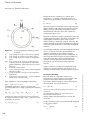
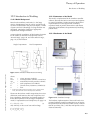
The parameters and variables are as in Figure 1, except
that here a distinction is made between the resistance,
compliance, and volume of the two compartments, and
Rt represents the resistance of the larger, upper airways
leading from the carina, (tracheal resistance).
∆ptot = (pAO – pBS) + ∆pmus = f1(υL) + f2(ύL)
The governing equations for this configuration are
(13)
where f1(υL) and f2(ύL) are functions of lung volume
change and flow. These functions can exhibit a variety of
nonlinearities, including hysteresis, power curves,
directional sensitivities, and time variation. In such
cases, the time constant may not be a mathematically
appropriate mechanical parameter. However, in some
situations, an average time constant with its concomitant
average resistance and average compliance, are used –
not necessarily correctly – to approximate the system
behavior.
Non-uniform Lungs
In some disease states, e.g., advanced COPD, tissue loss
and airway obstruction can be distributed in multiple
locations throughout the lungs. Consequently, a singlecompartment model does not describe the system’s
behavior very well. The minimum number of
compartments that will exhibit the essential responses of
such systems is two.
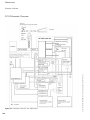
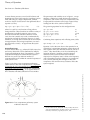
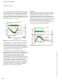
Figure 13-10 shows a two-compartment pulmonary
system within a chest wall compartment. It is important
to note that the two compartments do not necessarily
correspond to the two lungs. Instead, they represent the
aggregation, across both lungs, of all regions that have
time constants sufficiently different from one another.
(pAO – pC) = RtύL
(pC – pPL) = υL1/CL1 + R1 ύL1
(pC – pPL) = υL2/CL2 + R2 ύL2
(pPL – pBS) + Δpmus = υL/ CW
υL = υL1 + υL2
a)
b)
c)(14)
d)
e)
Combining these equations, and collecting terms yields:
Δptot + K Δptot = γ0υL + γ1 ύL + γ2ϋL
(15)
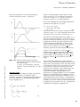
Equation (15) has the same form as the equation for an
isolated two-compartment pulmonary system (chest wall
and common airway not included) derived by Otis et al
(1956)1. They showed that, in such a relationship, the
apparent (dynamic) compliance and the apparent
resistance of the system each decrease from their
respective low frequency (static) values as the frequency
(rate) of breathing increases. Equation (15) extends Otis
et al’s work by showing how changes in chest wall
compliance and common airway resistance affects the
system response.
1
116
Otis AB, McKerrow CB, Bartlett RA, Mead J, McElroy MB, Silverstone NJ and Radford EP Jr. Mechanical Factors in Distribution of
Pulmonary Ventilation. J Appl Physiol 8:427, 1956.
User’s Manual ASL 5000, SW 3.5, Rev.2 © IngMar Medical, Ltd. 2015
Figure 13-10 Two compartment pulmonary system
within the chest wall.