1
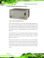
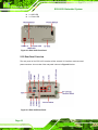
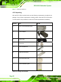
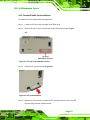
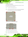
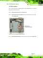
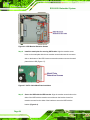
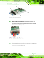
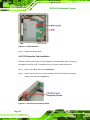
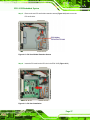
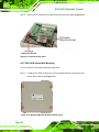
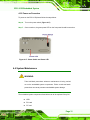
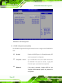
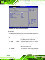
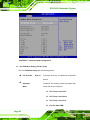
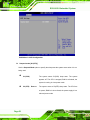
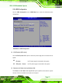
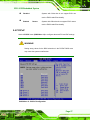
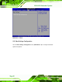
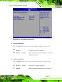
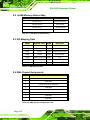
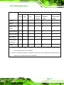
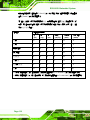
ECK-161B Embedded System
Step 2: Align the round retention screws on the first bracket with the ECK-161B
retention screw holes on the bottom of the chassis. Insert one of the retention
screws into each of the retention holes.
Step 3: Align the round retention screws on the second bracket with the ECK-161B
series retention screw holes on the other side of the bottom of the chassis. Insert
one of the retention screws into each of the retention holes.
Step 4: Drill four properly spaced holes into the surface on which the controller is going
to be mounted.
Figure 4-16: Wall Mounting Dimensions (mm)
Step 5: Insert one machine screw into each of the four retention holes on the bracket
and into the wall or surface on which the ECK-161B is mounted.
4.2.8 Cable Connections
Once the system has been mounted on the wall, the following connectors can be
connected to the system.
Audio jacks
Keyboard and mouse connectors
Power input connector
Page 29