1
DSPA64 User’s Guide
Release 02/01/98
Copyright (c), Symmetric Research, 1998
WARRANTY
LIMITED WARRANTY
WHAT IS COVERED
Symmetric Research warrants its DSPA64/DSPHLF product will be free from defects in
workmanship and materials for a period of three years from the date of original purchase.
WHAT SR WILL DO
Symmetric Research will repair or replace defective DSPA64/DPSHLF systems covered
under this warranty at no cost to the customer other than shipping. The customer is
responsible for shipping to SR manufacturing facilities.
WHAT IS NOT COVERED
Symmetric Research does not warrant the DSPA64/DSPHLF product for use with customer
provided power supplies or analog input voltages outside the range of values listed in this
manual. Incorrectly connecting power or analog inputs may permanently damage the boards.
Furthermore, DSPA64/DSPHLF systems that have been customer modified, including but not
limited to changes to the analog input voltage range circuitry, are also not covered under this
warranty.
Symmetric Research will at its discretion determine when any returned equipment has
been run from incorrect power supplies, incorrect analog inputs, or without AGND
connected, and is not covered by the terms of this warranty.
Symmetric Research is not liable for any loss, damage, or inconvenience, including direct,
special, incidental, or consequential damages, resulting from the use or inability to use the
DSPA64/DSPHLF product.
TABLE OF CONTENTS
Chapter 1: Introduction................................................................................. 1
Chapter 2: Installation................................................................................... 3
Chapter 3: Hardware basics .......................................................................... 9
Chapter 4: DLL Library support ................................................................. 17
Chapter 5: Finished Applications / Simpa64 / Scopea64 ............................ 27
Chapter 6: LabView Support ...................................................................... 29
Chapter 7: Low level example programs .................................................... 33
Chapter 8: System Diagnostic Utility.......................................................... 39
Appendix A: Electrical specs & Calibration ............................................... 41
Appendix B: DSPA64 circuit diagrams ...................................................... 43
Appendix C: DSPHLF circuit diagrams...................................................... 47
INTRODUCTION
INTRODUCTION
The Symmetric Research DSPA64 A/D data acquisition board provides an easy way to
acquire and process data on your PC from up to 64 channels at sampling rates from dc to
acoustic frequencies. It has been designed to work in conjunction with the SR DSPHLF
coprocessor board, providing the up front processing power of a DSP32C along with a full
1 Mb of buffering capability. The large buffering along with the transparent DSP32C host PC
interface allows for continuous real time data acquisition to the hard disk with no dead time.
Based on the Burr Brown DSP101 A/D converter, the DSPA64 has a single converter and a
64 channel analog multiplexer. The multiplexer is under program control of the DSPHLF
card, and can be set to scan the input channels in any order, making a new channel selection
between each sample. This provides considerable flexibility for scanning inputs from a
variety of sources, where the full sampling rate of the DSP101 can be spread across the 64
input channels in any manner. For example, when the DSP101 is sampling at the factory
default of 138 kHz and sampling is spread evenly across all 64 channels, an effective rate of
138/64 = 2.156 kHz on each channel results.
Software included with the board is aimed at providing support so data can be immediately
acquired and the user can become familiar with the board's technical operation. Source code
for all software is included so those interested in customizing the system for their own
applications have the information they need.
Other items included with the board include a 110 vac power supply, a ribbon cable for
connecting to a DSPHLF board, and complete circuit diagrams.
We hope you enjoy using the DSPA64 / DSPHLF system
1
INSTALLATION
INSTALLATION
HARDWARE INSTALLATION
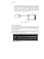
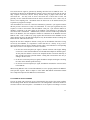
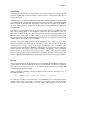
Hardware installation of the DSPA64 system is straightforward. Basically, the DSPHLF
board is plugged into the PC ISA bus, while the DSPA64 board sits outside the PC and is
connected to the DSPHLF via a ribbon cable. A power supply and your differential analog
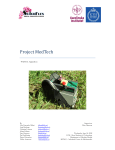
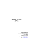
signal inputs must also be hooked up to the DSPA64. The basic configuration is indicated in
Figure 1, where the exact steps are:
1.
Install the DSPHLF DSP32C board in your PC's ISA bus. If you purchased your
DSPHLF and DSPA64 at the same time, all jumpers will be set correctly for normal
operation. Do not change them. For your reference, the default jumper settings are
listed later in this chapter.
2.
Plug one end of the 16 conductor twisted pair ribbon cable into the header JP80 of
the DSPA64, and the other end into the back bracket header of the DSPHLF board.
The cable is keyed so you are assured of proper installation. When properly
installed with the correct end plugged into the DSPA64, the cable will run away from
the DSPA64 board, not over it, and you should make sure the DSPA64 header
latches are engaged to hold the cable firmly in place.
3.
In order for the system to run, the DSPA64 must be supplied with power, where
several connector options are provided. The included power supply connects via a
standard DIN 5 pin connector to JP100. You may instead use either the Molex
connector JP101, or the terminal barrier strip S100 with your own power supply.
Connect power to only one of the three connector systems. Please refer to the circuit
diagrams at the back of this manual if you have any questions about the connections.
Note that the board should be supplied with three voltages, +5 for the digital
circuitry, and +/-12 for the analog. For tests over short periods of time, you may
optionally set jumper JP103 to pins (2,3) to draw the digital +5 from the analog +12
supply. We do not recommend running for extended periods of time in this mode.
Also note that connecting power supplies incorrectly to the DSPA64 may damage the
board permanently. If you are using your own power supply, check its values with a
voltmeter BEFORE turning the system on.
3
INSTALLATION
4.
To complete hardware installation, plug your signal sources into the input headers
JP10 to JP17 on the DSPA64. The channel numbers are indicated on the component
id markings on the board. Your signals should be differential, low impedance, and in
the range of +/- 2.75 volts. To avoid cross talk on unused channels, you may want to
short together or ground all unused inputs. You must also connect analog ground
to the screw terminals on the front edge of the board. Because the inputs are
differential, a good common analog ground connection is required.
DSPHLF
DSPA64
ANALOG INPUTS JP10 - JP17
16 CONDUCTOR CABLE
JP80
DSPA64 POWER SUPPLY CONNECTIONS
Figure 1: BASIC CABLING
DEFAULT JUMPER SETTINGS
The following tables list the factory default dip switch and jumper settings for both the
DSPHLF and DSPA64 boards. Unless you are knowledgeable in hardware functions and have
consulted the circuit diagrams at the back of this manual, we recommend using the factory
default settings shown here.
For the DSPHLF card, there is one dip switch and seven header blocks. They control items
like the PC IO base address occupied by the board, the DSP32C on board memory map, the
high speed serial interface, etc. Their functions are:
DSPHLF DIP SWITCH AND JUMPER FUNCTIONS
S600
JP100
JP300
JP400
JP401
JP403
JP500
JP600
PC IO base address dip switch
DSP32C memory map selection
External DSP32C interrupt header
DSP32C BACK BRACKET SERIAL PORT mode
DSP32C BACK BRACKET SERIAL PORT mode
Secondary DSP32C serial port header
DSP32C memory mode
PC ISA bus interrupt selection
Their default settings should be:
4
INSTALLATION
DSPHLF DEFAULT DIP SWITCH AND JUMPER SETTINGS
0x280 = 1↑ 2↑ 3↓ 4↑ 5↓
(↑ SWITCH ON,
(1:2 ON), ALL OTHERS OFF
ALL JUMPERS OFF
ALL JUMPERS ON
(11:12 OFF), ALL OTHERS ON
ALL JUMPERS OFF
(3:4 ON), soldered on at factory
ALL JUMPERS OFF
S600
JP100
JP300
JP400
JP401
JP403
JP500
JP600
↓
SWITCH OFF)
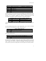
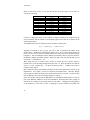
Generally, the only one of these that may need to be changed from its default setting is S600,
the PC IO base address dip switch. If an address conflict with another card in your system is
occurring, you can change the DSPHLF base address by setting S600 and the DOS
environment variable DSP32C_BASEIO appropriately. Some possible settings are:
ALTERNATE DSPHLF S600 BASE IO ADDRESS SETTINGS
0x280
0x300
0x340
0x100
1↑
1↑
1↑
1↑
2↑
2↑
2↓
2↑
3↓
3↑
3↑
3↑
4↑
4↓
4↓
4↓
5↓
5↓
5↓
5↑
Software default
SET DSP32C_BASEIO=300
SET DSP32C_BASEIO=340
SET DSP32C_BASEIO=100
Consult the SR DSP32C User's Guide for more information on setting the DSPHLF base
address.
As for the DSPA64 board, there are three jumper blocks. They control the DSPA64
conversion rate clock and digital power supply. Their functions are:
DSPA64 JUMPER FUNCTIONS
JP60
JP61
JP103
DSP101 conversion rate header
DSP101 clock source selection
Digital power supply option
Their default settings should be:
DSPA64 DEFAULT JUMPER SETTINGS
JP60
JP61
JP103
(3:4 ON) (5:6 ON) (13:14 ON), ALL OTHERS OFF
(1:2 ON) (3:4 ON), ALL OTHERS OFF
ONE JUMPER ON (1:2), ie external digital +5
The header JP60 is particularly critical to the system operation, controlling the aggregate
conversion rate of the DSPA64. Changing this jumper will change the time base of the
system. Setting it too fast may even short cycle the DSP101 into giving incorrect results.
Unless you have a good reason to change them, leave these jumpers set at the factory defaults.
5
INSTALLATION
TIPS FOR OPTIMUM HARDWARE PERFORMANCE
*
Do not touch the DSPA64 analog circuitry while it is in use. Your body has voltages
that will easily swamp out 16 bit accuracy.
*
All analog inputs should be driven by low impedance sources. Channels driven by
sources with high impedance are very susceptible to crosstalk. The low impedance
source requirement is imposed by switched multiplexer technology. A crude way to
ensure a low impedance source is to include a parallel resistor across the input. An
impedance in the range of 300-500 ohms or lower is ideal. A better way is to drive
the inputs with op amps having good current drive. Multiplexer characteristics are
discussed in more detail in the Hardware Basics chapter.
*
You may wish to provide a low impedance input to any channel not in use by either
shorting or grounding the inputs. Leaving a channel floating will not affect any other
active channels, but it will itself be susceptible to crosstalk from other channels if you
are monitoring it.
*
Make sure a good analog ground is connected from your equipment to the screw lugs
on the front edge of the DSPA64 board. Even though the DSPA64 inputs are
differential, they still require a good analog ground common reference point to avoid
clipping. Reliable operation of the DSPA64 requires at least one of the AGND
screw terminals S10-S12 to be connected to your system analog ground.
*
The DSPA64 board jumpers, JP60 and JP61, have been set for the optimal
conversion rate at the factory. Changing these jumpers from their default settings
will change the time base of the system, and may even short cycle the A/D
converter into giving completely incorrect results. Do not change them from the
defaults without consulting the circuit diagrams at the back of this manual and the
Burr Brown DSP101 spec sheets.
SOFTWARE INSTALLATION
The supplied software is on a single floppy disk in compressed PKZIP format. To install it,
run the install.bat file from the a: or other floppy drive. This will automatically unzip and
create the default \sr\dspa64 directory on your hard disk. All SR software products are
normally installed as subdirectories of \sr. We highly recommend you keep only one copy
of the software on your hard disk and that you use the default directory structure. This
makes maintaining your software and installing upgrades easier. However, if you need to
install the software in another directory, you may give the target drive and directory on the
install.bat command line.
6
INSTALLATION
For the most part all of the software has been written to be used with Win 95 and compiled for
32 bit execution. Limited support for 16 bit DOS execution is available in the
\sr\dspa64\16bit directory. The core of the 32 bit software is the DLL library dspa64.dll.
Include the directory \sr\dspa64\dll on your autoexec.bat execution path to make sure
these drivers can be found by applications at run time.
After software installation, you should verify correct operation of the system by running the
diag.exe program in the diags directory. It checks for proper DSPHLF and DSPA64 hardware
installation. Following that, you will probably want to run the scopea64.exe program to begin
experimenting with actually acquiring data.
The software is supplied with many readme.txt files and comments in the source code files.
Consult these areas for more online help and information.
7
HARDWARE BASICS
HARDWARE BASICS
This chapter covers the basics of how the DSPA64 hardware works. Being familiar with this
material will help you get the best performance from your system. While following the
descriptions given here, you may also want to refer to the circuit diagrams in the back of this
manual. If your interest is mainly in acquiring data immediately, you should proceed directly
to the Finished Applications / Simpa64 / Scopea64 chapter.
The circuit of the DSPA64 is straightforward. The analog portion of the board has a 64
channel analog multiplexer array, followed by an instrumentation amplifier and A/D
converter. The digital portion of the board takes care of controlling the A/D conversion rate,
receiving the next multiplexer channel from the DSPHLF DSP32C coprocessor board, and
sending the newly converted A/D values back to the DSPHLF.
The DSPHLF board is installed inside the PC and communicates with the DSPA64 via its high
speed DSP32C serial port. This is not an RS232 port. It is a 16 Mbit per second interface
designed primarily for communicating with devices like A/D converters.
The following descriptions cover the analog, digital, and power supply portions of the system:
ANALOG CIRCUITRY
The DSPA64 board has been designed to accept differential analog input signals. Your inputs
should be connected to the headers JP10 - JP17 on the front edge of the board, where there are
eight differential input pin pairs on each header. The differential +/- inputs must be
referenced to an analog ground, where screw lugs have been provided for making AGND
connections. If you have single ended inputs you can hook them up by connecting the single
ended input to the + pin for a channel, and connecting the - pin to your analog ground. Even
with single ended inputs you must still connect analog ground to the screw lugs.
Differential inputs are a powerful way of reducing system noise. Any common noise riding
on both the + and - inputs will automatically be canceled when the two are differenced in the
instrumentation amplifier following the multiplexer array. We recommend using twisted pair
cable to connect each of your inputs to the headers, where flat twisted pair ribbon cable is
readily available from suppliers such as 3M. Differential inputs along with oversampling and
signal averaging can often remedy noise problems in circuitry even in front of the DSPA64.
The DSPA64 has a two tier multiplexer array that has been designed for fast settling time and
low cross talk. The multiplexer array can be switched to a new input channel between each
9
HARDWARE BASICS
acquired sample, under program control of the DSPHLF card. This provides considerable
flexibility to scan the input channels in any desired order.
The first tier of the multiplexer array is comprised of eight 507A type differential multiplexer
chips located near the input headers. Internally, the 507A type mux chips have input current
limiting resistors to prevent any possibility of latchup and also to provide considerable
overvoltage protection. Each 507A has eight differential inputs, feeding into a single
differential output, where a 3 bit address selects which input is connected to the output.
The second tier of the multiplexer array is a single high speed 516 type multiplexer chip. This
chip selects the output from one of the first tier chips to pass on to the instrumentation
amplifier and A/D converter. Using a high speed mux in the second tier dramatically reduces
the settling time for the mux array. Like the 507A chips, the 516 has eight differential inputs
and a single output, along with a 3 bit address to select which input is connected to the output.
It differs from the 507A in that it has no input protection resistors and draws considerably
more current. This is an acceptable trade off in the second tier.
A 6 bit address controls which input channel of the entire multiplexer array is connected to the
instrumentation amplifier and A/D converter. This 6 bit address is transmitted to the DSPA64
board by the DSPHLF coprocessor card. The low 3 bits of the address go in parallel to the
first tier 507A chips, while the high 3 bits go to the second tier 516.
Users should take note that all multiplexer arrays are susceptible to cross talk. This is a
consequence of mux chip technology and is impossible to avoid. The reason for cross talk is
fairly simple. The output section of any multiplexer chip has a capacitance associated with it.
Charge remaining on this capacitance while switching channels leads to cross talk. For
example, suppose you are switching between two channels, where the first has a high voltage
and the second one is floating with a high impedance input. After the output capacitance of
the mux chip is charged up from the first input, it will have no way to discharge when you
switch to the floating channel.
You might think that connecting a low impedance to the mux output to discharge the voltage
would be a good solution. It is not because that would lengthen the RC charging and settling
time when switching to a new voltage and reduce overall sensitivity. The best solution is to
use low impedance inputs to the mux array. For unused channels, the easiest way to insure
this is simply to short their input pins together. Channels in use should either be driven by op
amps with low output impedance or be forced to low impedance by connecting a resistor
directly across the input. Generally a resistance in the range of 300 to 500 ohm is ideal. If
you follow the low input impedance requirement you will find that the multiplexer array has
excellent settling time and extremely low cross talk.
After selecting the input channel with the multiplexer array, further buffering of the signal is
done with an instrument amplifier. The factory supplied configuration is to use a Burr Brown
INA111 instrument amplifier to buffer the mux array output and convert the differential signal
to a single ended signal suitable for the A/D converter. This particular amplifier has very high
10
HARDWARE BASICS
input impedance, which is important for reducing the overall settling time of the mux array,
along with a very low noise characteristic.
The instrumentation amplifier portion of the input circuit has been designed to provide the
user with many possible options besides the factory supplied configuration. For example, the
INA111 gain can be set by a single resistor. The DSPA64 is shipped from the factory set for
unity gain, but you may want to set other values for your applications. Options have also been
provided for zener diode overvoltage protection, RC low pass filtering, and the use of other
amplifier chips besides the INA111. Users interested in pursuing these options should refer to
the Circuit diagrams appendix in making their selections. The factory configuration has been
found to give excellent overall performance.
Following the INA111 instrument amplifier is a simple resistor divider pair. Normally this is
set to provide no attenuation to the signal. When the INA111 is run at unity gain and the
resistor divider provides no attenuation, the system has the full scale voltage of the A/D
converter, +/- 2.75 volts. You can change the resistor divider pair to attenuate the full scale
voltage. The resistor divider pair, (R37,R38), has no significant loading, so the attenuation is
just their ratio. When increasing the full scale input voltage range, be aware that it is
ultimately limited by the BB INA111 instrument amplifier. When running off a +/- 12v power
supply the BB INA111 saturates at +/- 9.5 volts. Voltages beyond this range will not be
amplified linearly. See the Burr Brown spec sheets for more details.
After the resistor divider, the input signal is buffered through a BB OPA627 unity gain op
amp to the input of the Burr Brown DSP101 A/D converter. The switched capacitor
technology of the DSP101 input presents a widely varying load. This is more than adequately
buffered by the drive capabilities of the OPA627.
As for the A/D conversion, the DSP101 is a signed two's compliment device. Over its full
scale range of +/- 2.75 volts, +2.75 corresponds to a 16 bit count value of 0x7FFF (+32,767)
and -2.75 to a count value of 0x8000 (-32,768). The exact count/voltage ratio is covered in
the Calibration appendix of this manual. You should be aware that no A/D converter in the
real world can give exact reproducible results. The best that can be achieved is a spread of
values around some ideal. For example, if you are sampling 0 volts, you will only get a spread
of count values around 0x0000. Even Burr Brown admits this in the fine print of their spec
sheet, and states that to achieve full 16 bit accuracy requires averaging 256 consecutive
values. The oversampling and signal processing that is possible with the DSPHLF board
make it possible to realize these results.
Another factor to be aware of is DC offset voltages. No two mux channels are the same. This
results in slightly different DC voltage offsets from channel to channel. Generally these
values are small. To test them on your particular board, short all the input channels and
measure the resulting offset counts. The DSPA64 does not have any trim pots or other knobs
to twiddle DC offsets. A better way to take care of DC offsets is to adjust for them in
software. We recommend this approach if they are important for your application.
11
HARDWARE BASICS
After A/D conversion, digital output from the DSP101 A/D converter is transmitted in serial
format directly to the DSPHLF card as discussed in the digital overview next. The conversion
rate of the DSP101 is also controlled by the digital conversion rate clock in the digital section
next.
Finally, the DSPA64 board has been designed with split analog and digital power planes to
minimize noise. Following common design practice, the analog and digital ground planes are
optionally connected together at the DSP101, while separate positive analog and digital power
supplies are provided to further isolate digital noise. The factory installed jumper JP50
connecting the analog and digital ground planes at the DSP101 can be removed if desired.
Generally, we have found there to be little difference in performance.
DIGITAL CIRCUITRY
The DSPA64 communicates with the DSPHLF board through the DSP32C high-speed serial
port. This is not an RS232 port. It is a synchronous serial interface capable of 16 Mbit per
second data transfer rates that is specifically designed for interfacing with devices like A/D
converters. The interface has separate input and output channels so that communication in
both directions can occur at the same time. Both channels are often referred to as "three-wire
interfaces" because there are clock, data, and load signals.
On the DSPA64 board, the digital circuitry is divided into three sections. There are buffers to
interface to the DSPHLF serial interface, a serial to parallel byte wide register to receive the
multiplexer channel selection from the DSPHLF, and a bit clock/conversion rate generator to
set the aggregate conversion rate.
The buffers that interface the DSPA64 to the serial ribbon cable are differential 3486/3487
drivers. These drivers have excellent noise immunity, and are capable of driving long cables
at the high data rates used by the DSPA64. Even though the DSPA64 is supplied with a 7'
ribbon cable to connect to the DSPHLF card, we have used considerably longer cable with no
data errors.
The DSPA64 serial to parallel register latching the multiplexer channel to use for the next A/D
cycle is a 74HC595. The DSPHLF serial output is dedicated to transmitting the multiplexer
channel to this register on the DSPA64. The 6 bit channel selection that is latched into the
byte wide 74HC595 is fed directly into the multiplexer array address bits.
Finally, the bit clock and conversion rate generator on the DSPA64 are at the heart of the
digital portion of the circuit. The bit clock is set by the 10 Mhz crystal oscillator on the
DSPA64 and supplies both the clock tick to the DSP101, and the clock signals to the DSP32C
serial interface. To avoid any skew problems, the DSPA64 generates the clock signal for data
sent down to the DSP32C, and once the clock has arrived on the DSPHLF board, it is
retransmitted to the DSPA64 to synchronize the transmitted multiplexer channel.
12
HARDWARE BASICS
The conversion rate signal is generated by dividing down the basic 10 MHz bit clock. As
specified in its data sheets, the BB DSP101 requires at least 72 ticks of its bit clock in order to
fully complete conversions, and the factory default setting of jumper JP60 selects this
conversion rate. You may work at slower conversion rates of more than 72 ticks, but
generally we have found decimation from the fastest conversion rate to be a better way to
achieve lower sampling rates. Decimation from the fastest rate is the method used by the
scopea64.exe program for example.
After the DSP101 has received a conversion command, it generates a sync signal to indicate
that the previous conversion is ready to be transmitted. It is this sync signal that keys the
sequence of events in the interface with the DSP32C serial port. Sync from the DSP101 is
ultimately connected to the ILD signal on the DSP32C, and following its assertion, the
converted result is transmitted. Simultaneously with the converted result being transmitted
back to the DSP32C, the next multiplexer channel is transmitted to the DSPA64 from the
DSP32C obuf. This is enforced by tying together ILD and OLD on the DSPHLF card at
jumper JP400, and gives the DSPA64 multiplexer array the maximum amount of settling time
before the next A/D conversion occurs.
Despite the fact that a multiplexer channel is being sent to the DSPA64 while data is being
received by the DSPHLF, it is important to realize that there is a latency or lag of three
conversion pulses between when a channel selection value is sent and when its corresponding
data value is received. The sequence of events is as follows:
1 On the first conversion pulse/sync signal, a channel selection value begins shifting
out one bit at a time from the DSP32C into the DSPA64 multiplexer channel register.
At this point, the DSP101 converter has sampled and has conversion underway of
data from the previously specified channel. During this conversion the mux array is
settling to the new value.
2 On the next conversion pulse/sync signal, the DSP101 samples and begins converting
the value on the channel specified in step 1.
3 On the next conversion pulse/sync signal, the DSP101 transmits the converted value
to the DSP32C.
When writing DSP32C code to control the DSPA64, be sure to properly initialize the DSP32C
serial port IOC register. Refer to chapter 5 of the AT&T WE DSP32C Information manual
for a complete description of the DSP32C's serial interface.
CONVERSION RATE JUMPERS
The rate at which A/D conversion occurs is determined by the speed of the crystal oscillator
and the timing header JP60 on the DSPA64 board. The timing header controls the number of
clock tics between conversion pulses. A minimum of 72 are required. The timing is set at the
13
HARDWARE BASICS
factory as shown in the Circuit diagrams appendix and in the default jumper settings covered
in the INSTALLATION chapter.
The 12 bit timing count specified by the header provides the starting value for the counter,
which then increments with each clock tic and outputs a conversion pulse when it rolls over
from 0xFFF back down to 0x0. The start count is read from the timing header as a binary
number.
POWER SUPPLY
The DSPA64 board requires three power supply voltages to operate. These are +5 vdc to run
its digital circuitry, and +/- 12 vdc to run its analog section. Using separate power supplies for
the digital and analog sections reduces the amount of digital noise appearing in converted
values.
To further help reduce noise and keep the analog section quiet, the DSPA64 is a multilayer (4)
board with split digital and analog ground planes. This keeps digital switching noise isolated
from the analog circuitry. If you hold the board up to a bright light, you will be able to see the
split planes on the inner layers.
Within the analog section, the multiplexer array and BB INA111 instrumentation amplifier run
at the full +/- 12 vdc of the analog supplies. However, the DSP101 is designed to run at +/- 5
vdc, and its voltages are derived through regulators U101 and U102. The OPA627 op amp
buffering the input of the DSP101 is also run with +/- 5 vdc. The current requirements of the
DSP101 and OPA627 are modest and you will find the regulators U101 and U102 run at very
cool temperatures.
Running the multiplexer and INA111 at 12 volts allows for higher level inputs that exceed the
+/- 2.75 vdc input of the DSP101. These higher level inputs can then be attenuated by the
resistor divider at the INA111 output down to the +/- 2.75 input of the DSP101. With the 12
volt supply, you will find that the INA111 saturates at about 9.5 volts as stated in the Burr
Brown spec sheet. The maximum analog input voltage can be further extended by installing
the optional resistor dividers at the input of the INA111, but if you do so, use matched 1%
resistors to avoid affecting the common mode rejection ratio.
As an option, power for the digital circuitry can be derived from the +12 vdc analog supply.
This option is selected by setting jumper JP103 to positions (2,3). We do not recommend
using this option for extended periods of time. It is much better to run the digital circuitry
from its own power source. The triple output power supply included with the DSPA64
provides an independent +5 vdc, and jumper JP103 should normally be in position (1,2).
Depending on the length of ribbon cable you use to connect the DSPA64 to the DSPHLF card,
the digital section can use up to 300 ma of current. This results in fairly high levels of heat
14
HARDWARE BASICS
dissipation in U100 when deriving the digital supply from the analog +12 vdc. While within
the specifications for a 7805, heat dissipation is not ideal for long term operation.
With modest care, you will find the DSPA64 board can run from a wide variety of power
sources. However, supplying power incorrectly to the board can damage it. Typical mistakes
would be reversing the +/- 12 vdc analog voltages or reversing the +5 vdc digital supply and
ground. While the id markings on the board are clear for the barrier terminal strip S100, you
must carefully consult the circuit diagram if you are using the Molex connector J101. The
Molex connector is polarized to help make the connections correctly, but if you have any
doubts, measure your supply and pin outs with a voltmeter BEFORE connecting power. The
5 pin DIN connector on the included power supply is polarized and is virtually impossible to
connect incorrectly.
Finally, we highly recommend connecting the AGND screw terminals S10-S12 on the front
edge of the board to the analog ground in your system. Establishing a good analog ground is
important for two reasons. First, the differential inputs must be referenced to a ground
voltage. Even though they are differential, they only operate in a differential fashion up to the
analog power supply rails. If you leave the DSPA64 board floating, its ground reference can
slowly drift with respect to the analog inputs and pin them at the power supply maximums.
Secondly, providing a good analog ground provides a easy path for overvoltages and surges to
flow off the board reducing the likelihood of damage to the circuitry.
Note that the power supply included with the board is isolated from the wall socket and you
cannot rely on the ground pin on the 110 vac plug to establish analog ground. Also note that
the mounting holes on the board are insulated from the ground planes and cannot be relied on
to establish analog ground either. Reliable operation of the DSPA64 requires at least one
of the AGND screw terminals S10-S12 to be connected to your system analog ground.
15
DLL LIBRARY SUPPORT
DLL LIBRARY SUPPORT
Win 95 32 bit DLL library support is at the core of the software supplied with the SR
DSPA64/DSPHLF system. With these functions, system operation can be controlled from
high level languages without having to know the low level details. These functions can be
called from Microsoft Visual C and Basic, and National Instruments LabView. This chapter
covers usage from programming environments like Visual C. For information about usage
from LabView, see the LabView chapter. For low level programming information see the
Low Level Examples chapter.
The general outline of how to use the dspa64.dll functions is fairly simple. There is an Init
function to set the channels to be scanned and other parameters. Once the board has been
initialized, then the Start function should be called to begin execution. While executing,
IsReady can be called to determine when the DSPA64 has acquired data, and be followed by
calling GetData to copy the data from the DSPHLF board into PC memory. The data can then
be displayed or saved to hard disk by the user. Note that transfer of data from the DSPHLF to
the PC’s memory is transparent to all data acquisition. Acquisition continues on without
interruption.
There are generally two schemes for determining when IsReady comes true. The first is
infinite loop polling. While easy to program, this method wastes considerable PC horsepower.
A much better way is to set up a PC timer tick that will test the IsReady function slightly more
often than the DSPA64/DSPHLF becomes ready. This method greatly reduces the number of
PC cycles used in polling and fits in very well with the multitasking capabilities of Win 95.
It is also possible to have the DSPA64/DSPHLF interrupt the PC when it is ready with data.
Generally there is little improvement in performance using interrupts over a timer tick.
Interrupts are considerably more difficult to use with Win 95 than timer ticks, and a timer tick
is recommend for most applications.
When using the dspa64.dll library, be sure to include the header file dspa64.h in any C source
code. The prototypes in this file make sure that the correct parameters are passed to the
functions. You will also find the defined constants in dspa64.h useful for making your
programs more readable. Also make sure the dspa64.dll library is on your execution path so
Windows can find it at run time.
16 bit DOS users can recompile the DSPA64/DSPHLF library to a standard static LIB. See
the \sr\dspa64\16bit directory for examples of how to do this.
The following is a discussion of each dspa64.dll function. Refer to the programs simpa64.c
and scope.cpp for complete examples of how to use the library functions.
17
DLL LIBRARY SUPPORT
SET THE DSPA64/DSPHLF PC BASEIO ADDRESS
C usage:
#include "dspa64.h"
void DSPA64_SetBaseio( unsigned value);
int DSPA64_GetBaseio( void);
These two functions will set and report the PC IO space base address that the DSPHLF board
occupies. Normally they do not need to be called. By default the software will assume the
DSPHLF board is at the address 0x280. See the Installation chapter for more details.
If you are working with a non default base address, call SetBaseio to set a value that agrees
with the on board DIP switches. Do this call before calling Init.
You can also run more than one DSPA64/DSPHLF system in your PC at the same time by
setting each to a different PC BASEIO address and interleaving calls to the other dspa64.dll
functions with calls to SetBaseio to communicate with the appropriate board.
18
DLL LIBRARY SUPPORT
INITIALIZE THE DSPA64/DSPHLF
C usage:
#include "dspa64.h"
int DSPA64_Init(
int nchannel,
int nsample,
int ncount,
float filter_coeff,
float filter_scale,
int *scan_list
);
This function initializes the DSPA64/DSPHLF system. If it is successful it will return a 1,
otherwise 0. It takes several parameters controlling various system features, and besides
initializing, can be used as a system presence test.
The first three parameters set very general system criteria relating to buffer size and sampling
rate. Nchannel specifies the total number of channels that are to be scanned. It should be > 0
and <= 64. Nsample specifies the number of samples to be acquired on each channel per
buffer. Thus total acquisition buffer size is:
Acq buffer size in bytes = nchannel * nsample * sizeof( short int)
The parameter ncount sets the sampling rate by controlling the decimation applied to the
incoming data. For most systems, the A/D will sample at 138 kHz, and this is spread evenly
across all the scanned channels. This basic rate can then be further decimated by specifying
ncount. Ncount = 0 specifies no decimation, ncount = 1 saves every other sample and so on.
Arbitrary exact sampling rates cannot be specified, only those achievable by decimation.
However, given a desired sampling rate, the corresponding best value of ncount can be easily
calculated by calling the SpsToNcount helper described in the next function group. More
details about the scanning and decimation can be found in the Hardware Basics chapter.
The next two parameters, filter_coeff and filter_scale, set the two term oversampling filter that
will be applied to the incoming data. Even though you may be decimating to a lower sampling
rate, intervening data need not be thrown away. It can be signal averaged by the DSPHLF to
increase effective system resolution. The value of filter_coeff should always be between 0.0
and 1.0, while the filter_scale is normally set to be 1 – filter_coeff. The filter can be entirely
turned off by setting filter_coeff = 0.0 and filter_scale = 1.0. See the helper functions
19
DLL LIBRARY SUPPORT
TailToCoeff and NormalizeScale for an easy way to compute these parameters. See the Low
Level Examples chapter and filter.dsp for a complete discussion of two term filtering.
Finally, scan_list specifies the order in which you want the input channels to be scanned. This
should be an array of ints, listing the scanning order:
int scan_list[ NCHANNEL];
where NCHANNEL should be the number of channels specified in the nchannel parameter.
Any channels can be listed in any order. For example, if you wanted to scan every other
channel in the first eight, you might specify scan_list = { 0, 2, 4, 6 }.
A typical calling sequence for Init would be:
#include "dspa64.h"
nchannel = 3;
nsample = 512;
SpsToNcount( 1000, &ncount);
filter_coeff = .6;
filter_scale = .4;
scan_list[0] = 0;
scan_list[1] = 1;
scan_list[2] = 2;
if ( !DSPA64_Init(
nchannel,
nsample,
ncount,
filter_coeff,
filter_scale,
scan_list,
) )
printf( "error, unable to initialize");
This would scan the input channels, 0, 1, 2, saving 512 points per acquisition buffer at a final
sampling rate of 1000Hz per channel, with a mild oversampling filter applied.
For further examples of how to use Init, see the source code for the finished applications
simpa64.c and scope.cpp
20
DLL LIBRARY SUPPORT
HELPER FUNCTIONS
C usage:
#include "dspa64.h"
void
void
void
void
void
void
void
void
DSPA64_BufferSize( int nchannel, int nsample, int *nbytes );
DSPA64_SpsToNCount( int nchannel, float sps, int *ncount );
DSPA64_NCountToSps( int nchannel, int ncount, float *sps );
DSPA64_TailToCoeff( int ncount, float tail, float *coeff );
DSPA64_CoeffToTail( int ncount, float coeff, float *tail );
DSPA64_NormalizeScale( float coeff, float *scale );
DSPA64_NTimingTicks( int newticks, int *nticks );
DSPA64_MaximumRate( float *maxrate );
These helper function can make it easy to compute system parameters for functions like Init
and GetData.
For their precise results, refer to the C source code for the DSPA64 DLL library, dspa64.c. In
general the two helpers of greatest interest are BufferSize and SpsToNCount.
Use the function BufferSize to compute the size of the acquisition buffer for use with GetData.
A buffer of this size should be declared in your program to store acquired data in on its way to
the display or hard disk.
Use SpsToNCount to compute the ncount decimation parameter to use with Init, given your
desired sampling rate. Since sampling rates are only achieved by decimation, you can also use
the inverse function NCountToSps to compute the exact sampling rate the system actually
returns.
For more discussion of the filter coefficients, see the filter.dsp example in the Low Level
Examples chapter. The helper functions listed here make it easy to compute final values from
your basic design requirements.
Finally, the NTimingTicks and MaximumRate functions are for advanced applications that
will be changing the timing jumper settings on the DSPA64 board. Do not change these
settings unless you have read the Hardware Basics chapter and know what you are
doing.
21
DLL LIBRARY SUPPORT
START AND STOP EXECUTION
C usage:
#include "dspa64.h"
void DSPA64_Start( void );
void DSPA64_Stop( void );
After successfully initializing the DSPA64, you will want to start it executing. Calling Start
begins converting and saving data to DSPHLF on board memory. Until Start is called the
system is held in idle mode is not sampling the analog inputs.
Usually once execution is started you will want to begin testing for when the
DSPA64/DSPHLF is ready with an acquisition buffer of data. Use the IsReady function to
test for that condition and GetData to transfer the acquired data over to the PC.
At the close of your program you may wish to call the Stop function to halt the
DSPA64/DSPHLF and stop execution. Calling Stop is optional, but if you do not the system
continues executing and sampling the analog inputs.
22
DLL LIBRARY SUPPORT
IS DATA READY
C usage:
#include "dspa64.h"
int DSPA64_IsReady( void );
void DSPA64_ClearReady( void );
Once the DSPA64/DSPHLF has started executing, the function IsReady should be called to
see when data is ready for downloading to the PC. If it returns a non zero value, data is ready,
while 0 indicates you should continue waiting.
The DSPHLF card maintains two acquisition buffers for acquiring data. When one buffer is
full, IsReady will signal with a non zero value and automatically start saving incoming data in
the other buffer. By ping ponging between the two buffers, continuous acquisition is possible
with no data lost. The non zero value returned by IsReady indicates which buffer is ready.
Once data is ready, call GetData to transfer it to the PC. Getting data will automatically set
IsReady back to 0 and the application program can then continue waiting. Save the value
returned by IsReady for use with GetData. The value will indicate to GetData which buffer is
ready. You do not need to know the value of the non zero value, simply pass it to GetData
and it will automatically get the correct buffer.
IsReady should be tested by infinite loop polling or a timer tick to see when data has become
ready and should be processed by the PC. Generally polling via a timer tick is preferred
because that makes better use of the PC’s cpu.
To check for data overflow, simply call IsReady again immediately after calling GetData. If it
returns a nonzero value, then data is coming in so fast that the PC is unable to keep up with it.
The finished application programs simpa64.c and scope.cpp both show how to use the
IsReady and GetData functions to interact with the DSPA64/DSPHLF system.
ClearReady is included only for those wishing to make doubly sure IsReady is cleared. This is
not normally required. Init and GetData both leave the flag cleared.
23
DLL LIBRARY SUPPORT
GET DATA
C usage:
#include "dspa64.h"
int DSPA64_GetData( int status, short int *pcbuffer, int nbytes );
Once the IsReady function has returned true, you should call GetData to download the
acquired data for further processing. To use GetData, allocate an array of short integers in
your program as:
short int *pcbuffer;
pcbuffer = (short int *)malloc( NBYTES);
Where NBYTES should be the size of the acquisition buffer as defined by the parameters
passed to Init, ie:
NBYTES = nchannel * nsample * sizeof( short int);
or
DSPA64_BufferSize( nchannel, nsample, &NBYTES);
Pass the pcbuffer address and size to GetData. The status parameter should be the non zero
return value from IsReady. This value indicates which of the DSPHLF acquisition buffers is
ready with acquired data.
How is the data returned by GetData organized? Returned A/D values are 16 bit signed short
integers. Values from each channel are multiplexed one after the other in the buffer. The first
value from the first channel scanned will be in pcbuffer[0], the first value from the second
channel in pcbuffer[1], and so on. The second converted value from the first channel will be
in pcbuffer[nchannel], and in general the value from the nth conversion on channel c will be:
Value at nth conversion from channel c = pcbuffer[n*nchannel + c]
24
DLL LIBRARY SUPPORT
A typical calling sequence for GetData would be:
/* Allocate an array to save acquired values in */
DSPA64_BufferSize( nchannel, nsamples, &nbytes);
pcbuffer = (short int *)malloc( nbytes);
... initialize the board and start execution ...
while ( 1 ) {
if ( status = DSPA64_IsReady() ) {
/* Get the data. */
DSPA64_GetData( status, pcbuffer, nbytes);
/* Do something with it ... */
SaveValuesToDisk( pcbuffer);
}
}
See the finished application programs simpa64.c and scope.cpp for additional code listings
showing how to use these functions.
25
FINISHED APPLICATIONS / SIMPA64 / SCOPEA64
FINISHED APPLICATIONS / SIMPA64 / SCOPEA64
The SR DSPA64/DSPHLF comes with two finished Win 95 application programs you can run
immediately after installing the hardware and software. These programs will help you become
more familiar with the system, and may fill your entire acquisition needs. The source code is
included for those wanting to modify the programs for custom applications.
Simpa64.exe is a simple text only command line program, while scopea64.exe is a full Win 95
graphical user interface GUI display program. Both save their output data to binary files in
the same format for further processing. They have been written in C and C++ respectively,
and their source code can be found in simpa64.c and scope.cpp.
Following are brief summaries of each program. For more details, refer to the readme.txt files
and source code comments in the respective directories.
simpa64.exe
This program is a simple text only acquisition kernel. It is designed to be run from the Win 95
DOS command line, and will save its data to an output file.
This program is appropriate for applications divided between many windows, where one
window would be running simpa64.exe while other windows would be processing and perhaps
displaying the simpa64 data files downstream.
The initialization parameters for simpa64.exe are specified in the file simpa64.ini. Refer to
that file for more comments about its syntax and parameters.
If you have trouble running simpa64.exe it may be because the system cannot find the
dspa64.dll library at run time. Make sure \sr\dspa64\dll is on your execution path so the DLL
library can be found at run time.
A 16 bit version of simpa64.exe can be found in the \sr\dspa64\16bit directory. This version
of the program is suitable for running from a Windows 3.1 or 16 bit DOS command line. See
the readme.txt file in the 16bit directory for more information about how to build 16 bit
applications.
27
FINISHED APPLICATIONS / SIMPA64 / SCOPEA64
scopea64.exe
This is a full Win 95 GUI application. It will display your data as horizontal traces on the
screen in scope like fashion, and also save the output data to binary files in exactly the same
format as simpa64.exe.
To start scopea64.exe, execute it from the Win 95 DOS command line or the Win 95 Start
menu Run command. After the program is running, menu commands will be displayed across
the top of the screen. You can select from these to control program features. In addition to
controlling items like the sampling rate, you can also control the output file naming, and
display properties. Refer to the online help and readme.txt file for more information about
scopea64.exe.
There is no 16 bit version of the scopea64.exe program. It is assumed that users wanting
graphical output will at least be running Win 95. However, for LabView users, there is a
finished scope like application program written in LabView. Refer to the \sr\dspa64\labview
directory and LabView chapter for more information.
28
LABVIEW SUPPORT
LABVIEW SUPPORT
Support for National Instruments LabView is provided in the LabView LLB VI library
\sr\dspa64\labview\dspa64.llb. This LLB contains 1 application and 18 utility VIs. The scope
application VI is a complete data acquisition program that relies on the underlying utility VIs.
The utility VIs are in turn wrappers around the corresponding core dspa64.dll DLL functions
which supply the low level support for all SR DSPA64 software.
To use the DSPA64 LLB library, first put \sr\dspa64\dll on your path so Win 95 can find the
core DLL at run time. You can then access the VIs in dspa64.llb by using the File>Open
menu option to open \sr\dspa64\labview\dspa64.llb. Alternatively, it may be more convenient
to have those VIs available from the User Libraries button on the Function Palette. You can
do this using the Edit>Edit Control & Function Palettes... menu option or by copying
dspa64.llb into the user.lib subdirectory of your LabView directory. For further details, please
refer to file \sr\dspa64\labview\readme.txt.
The DSPA64 application VI is described below. For additional information, please refer to
the descriptions of the underlying DLL functions or use the Window>Show VI Info... menu
option to access the information stored within each VI itself. The application and utility VIs
have been saved unlocked and with their block diagrams included so that you can modify them
as needed to fit your application.
DSPA64 Scope Demo
The DSPA64 scope demo displays acquired values as horizontal waveforms like an
oscilloscope. The display is not as robust as the finished Win 95 scopea64.exe, but does show
how to go about programming such an application in LabView. Besides displaying data, both
a header file containing information like the channels and sampling rate, and a binary data file
containing the data points are written out to the LabView default directory that is set from the
Edit>Preferences menu option. These files use the same format as those output by the C
language programs simpa64.exe and scopea64.exe.
After the front panel controls have been set and execution started, the DSPA64/DSPHLF
system is initialized, the header file is written, and acquisition begins. The program works by
testing the IsReady function with a timer tick, seeing when data is ready to be moved over to
the PC’s main memory with the GetData function. The data is then written out to the hard
disk and displayed on the multiplot graph on the screen.
To run the program, press the Run Arrow on the toolbar. This enables the Sample Rate dial
and the Filter Coefficient field. Once you have set these controls to their desired values, press
29
LABVIEW SUPPORT
the green START button to begin acquisition. Acquisition will continue until you press the
red STOP button to end the demo.
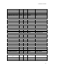
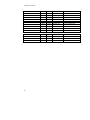
DSPA64 Utility VIs
The following table lists the utility VIs in dspa64.llb and their arguments. In order to allow
complete flexibility for controlling the flow of execution, dummy inputs and/or outputs are
provided for any function not having at least one input and output. DSPA64 Start is an
example.
Function
In/Out
Type
DSPA64 Init
input
input
input
input
input
input
output
int32
int32
int32
single
single
int32*
int32
nchannel
nsample
ncount
filter coeff
filter scale
scan list
init result
1 to 64
>0
>= 0
0.0 to 1.0
0.0 to 1.0
0 to 63
1 ok, 0 failure
DSPA64 Start
input
output
int32
int32
flow in
flow out
dummy
dummy
DSPA64 Is Ready
input
output
int32
int32
flow in
ready result
dummy
0 not ready, 1/2 ready
DSPA64 Get Data
input
input
input
output
output
int32
int16*
int32
int32
int16*
status
pcbuffer in
nbytes
get data result
pcbuffer
0 not ready, 1/2 buffer id
placeholder for data
>0
1 data read, 0 not
array of int16 values
DSPA64 Stop
input
output
int32
int32
flow in
flow out
dummy
dummy
DSPA64 Sps To Ncount
input
input
output
int32
single
int32
nchannel
samples / sec
ncount
1 to 64
1.0 to 138888.9 Hz
>= 0
30
Description
Range
LABVIEW SUPPORT
DSPA64 Ncount To Sps
input
input
output
int32
int32
single
nchannel
ncount
samples / sec
1 to 64
>= 0
1.0 to 138888.9 Hz
DSPA64 Coeff To Tail
input
input
output
int32
single
single
ncount
coeff
tail
>= 0
0.0 to 1.0
0.0 to 1.0
DSPA64 Tail to Coeff
input
input
output
int32
single
single
ncount
tail
coeff
>= 0
0.0 to 1.0
0.0 to 1.0
DSPA64 Normalize Scale
input
output
single
single
coeff
scale
0.0 to 1.0
0.0 to 1.0
DSPA64 Buffer Size
input
input
output
int32
int32
int32
nchannel
nsample
nbytes
1 to 64
>0
get data array size
DSPA64 NTiming Ticks
input
output
int32
int32
newticks
nticks
72 to 4097
72 to 4097
DSPA64 Maximum Rate
input
output
int32
single
flow in
maxrate
dummy
1.0 to 138888.9 Hz
DSPA64 Clear Ready
input
output
int32
int32
flow in
flow out
dummy
dummy
DSPA64 Get Baseio
input
output
int32
int32
flow in
baseio
dummy
0x000 to 0xFFF
DSPA64 Set Baseio
input
output
int32
int32
baseio
flow out
0x000 to 0xFFF
dummy
DSPA64 Write Header
File
input
int32
data coding
1 (0 = offset, 1 = signed)
input
input
int32
int32
word size
record pts
2
nsample
31
LABVIEW SUPPORT
DSPA64 Write Data File
32
input
input
input
input
input
input
input
input
input
input
output
int32
path
string
error
int16*
string*
single
single
single
single
error
channels
file name
id
error in
channel array
channel title
sample rate
gain
filter coeff
filter scale
error out
nchannel
scope.hdr
SR DSPA64
input
input
input
output
path
int16*
error
error
file name
wave array
error in
error out
scope.out
acquired data values
0,1,2,…63 default
[64], 12 char
1.0 to 138888.8 Hz
1.0
0.0 to 1.0
0.0 to 1.0
EXAMPLES
LOW LEVEL EXAMPLE PROGRAMS
Low level example programs are included with the DSPA64/DSPHLF for users wishing to
understand the fundamental programming details of the system. These examples progress
from simple to more complex with config.dsp approaching the core DSP driver used with the
finished applications simpa64.exe and scopea64.exe.
All of the examples can be found in the \sr\dspa64\examples directory after software
installation. Most are designed to be run by hand in the DSPHLF DSP32C DSPMON
monitor. See the SR DSP32C software and User's manual for more information about this
software tool.
A brief overview of each program is covered in this chapter. For more details the user should
refer to the comments in the respective source code file.
sample.dsp .................................................................................................. 34
sample18.dsp .............................................................................................. 35
filter.dsp...................................................................................................... 35
switch.dsp ................................................................................................... 37
iconfig.dsp .................................................................................................. 37
config.dsp ................................................................................................... 38
33
EXAMPLES
sample.dsp
This program demonstrates some of the typical steps for reading data values from the DSPA64
board and saving them to memory on the DSPHLF board. It forms the basis of many of the
other supplied programs and is a good example to understand. To run it, execute sample.dso
by hand from inside the DSP32C DSPMON monitor.
The flow of the program is to first initialize the DSP32C serial port for 8 bit output and 16 bit
input. In the DSPA64/DSPHLF system the DSP32C serial output channel is dedicated to
selecting the multiplexer channel, while the input channel receives the acquired data.
Following the DSP32C serial port initialization, obuf is programmed with the mux channel to
use, and then a polling loop is entered waiting for acquired values to be received in ibuf. For
simplicity, obuf is not changed inside the polling loop, so the same channel is continually
sampled and saved.
Because it executes endlessly until the DSP32C is explicitly halted, simply quitting DSPMON
will leave the DSP32C running and the acquisition process underway. To halt the processor,
execute the DSPMON h command, or if you are at the DOS prompt restart DSPMON which
does an automatic halt as part of initializing the DSP32C. A benefit of using a DSP chip for
front end processing is that you can be at the OS level doing other operations while your
acquisition process continues on independently.
To examine the acquired 16 bit values you should use the DSPMON dw, display memory,
command to look at the contents of the circular VALUES buffer. Be aware that the first three
values returned from the DSPA64 are not valid since they are returned before the DSPA64
acquisition pipeline has had time to clear. Also note that values can be examined while the
DSP32C is executing. This is another benefit of using a front end processor like the DSP32C.
With its transparent host PC interface, all of its on board memory is available to the PC at all
times. This allows for completely uninterrupted data acquisition.
To summarize, the typical program flow includes at least:
1.
2.
3.
Initializing the DSP32C serial port
Setting the multiplexer channel
Entering a polling loop, checking ibuf for values to save to DSP32C memory
More complicated programs add items like scanning the multiplexer channels, downloading
data to the hard disk, and having the PC take care of managing the system rather than just
running a stand alone program by hand in DSPMON.
34
EXAMPLES
sample18.dsp
The sample.dsp program above saved its data as 16 bit values. However, as many users will
be aware, the BB DSP101 A/D is actually an 18 bit converter. This program shows how to
save the full 18 bits.
Sample18.dsp is very similar to sample.dsp except that it programs the DSP32C serial port for
32 bit input and saves the full long integer value to memory from ibuf. Note that because the
DSP101 outputs its data MSB first, the acquired 18 bit values will be aligned in the MSBs of
the 32 bit memory location. Display the acquired values with the DSPMON dl command to
show this result.
The DSP32C has no straightforward way to convert the 18 bits located in the MSBs of a 32 bit
long word to floating point. If your application requires the full 18 bit DSP101 result, you
may wish to consider saving your data in purely integer format or executing instructions to
shift the result down to the 24 LSBs of the 32 bit word for subsequent floating point
conversion and processing. For hardware people, the DSP101 uses the ILD before data mode
of the serial port, forcing the 18 bits to the MSBs.
Generally, treating the results returned from the DSPA64 as 16 bit values is a good match
between the characteristics of the DSP32C and DSP101. Some of the reasons are: 18 bit data
is inconvenient for storage. Using 32 bits to gain an additional 2 bits of resolution is not
warranted in most applications. Additionally, although it is an 18 bit converter, the DSP101 in
practice achieves that resolution only with considerable oversampling. The oversampling
required for full 18 bit accuracy can become excessive. Finally, converting 18 bit integer
values to floating point involves considerable bit twiddling. Because of these reasons, the
software supplied with the DSPA64 has been designed to treat acquired values as 16 bit data.
filter.dsp
This program demonstrates the application of a two term Infinite Impulse Response (IIR) filter
to 16 bit values as they are acquired in real time on a single channel. The filter covered here is
very simple, but it shows how easy it is to add and change features like averaging and
oversampling with digital processing.
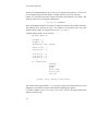
Start by considering computing a running weighted average of incoming data values, x[n]. A
reasonable equation is:
f[n] = SCALE*( x[n] + c*x[n-1] + c2*x[n-2] + c3*x[n-3] + ... )
For values of c less than 1.0, the coefficients cn are diminishing in size, and a stable weighted
average of the previous values results. For values of c greater than 1.0, the filter is obviously
unstable. This is typical of IIR filters. For some values of their parameters they are stable,
35
EXAMPLES
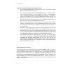
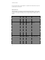
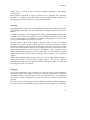
while for others they are not. To see how the tail dies off for the values of c less than 1.0,
consider the following:
power of c
1
2
3
4
5
6
7
8
9
10
11
12
c = .9
0.9000
0.8100
0.7290
0.6561
0.5905
0.5314
0.4783
0.4305
0.3874
0.3487
0.3138
0.2824
c = .4
0.4000
0.1600
0.0640
0.0256
0.0102
0.0041
0.0016
0.0007
0.0003
0.0001
0.0000
0.0000
Clearly, by changing the value of c the number of samples included in the weighted average
can be controlled, and the amount of oversampling applied to the data can be tailored to the
signal being acquired.
To implement this filter, the following recursive formula is usually used:
f[n] = SCALE*x[n] + COEFF*f[n-1]
Applying it repeatedly to f[n-1], f[n-2], you can see that it reproduces the infinite series
formula above. Rather than computing the infinite series out to some specified number of
terms over and over, this recursive formula achieves the same result with a minimum of DSP
horsepower. The two multiplies and one addition per incoming value are a perfect match for
the DSP32C multiply accumulate pipeline. When you want to turn low pass filtering off, just
set COEFF = 0.0 and SCALE = 1.0.
When using this type of recursive filter, SCALE is usually chosen so that the output is
normalized to 1.0 for incoming samples having the value 1.0. Since the infinite series has the
value 1/(1-c) for constant x[n] = 1.0 input, choosing SCALE = 1-COEFF will result in
normalized filter output.
More complicated filters with different tail shapes or other filter characteristics clearly can be
implemented. For example, you may be interested in bandpass filters. Obviously though,
more complicated filters will require more instructions and time to compute. So just how long
does the DSP32C have between incoming samples to compute ?
Since each sample acquired with the BB DSP101 on the DSPA64 board requires at least 72
ticks of the DSPA64 10Mhz bit clock, and each DSP32C instruction takes 80ns, roughly 90
instructions are available for processing between each sample. Changing the timing jumpers
on the DSPA64 to more than 72 ticks or changing its crystal oscillator will modify this
36
EXAMPLES
number, and let you have a trade off between maximum sampling rate and available
processing time.
Ninety DSP32C instructions is enough processing time to implement some interesting
algorithms. Try hooking up an analog input and experimenting with the coefficients in
filter.dsp to get a feel for the results of a very simple two term filter.
switch.dsp
This program shows a simple way to switch multiplexer channels while acquiring data. It does
so by computing and setting a new mux channel each time a DSPA64 value is received by the
DSP32C.
To switch the multiplexer, obuf is toggled between 0 and 1 inside the acquisition polling loop.
Acquired values from these two channels are saved in multiplexed fashion in the VALUES
array. To examine them, use the DSPMON dw command. This displays the 16 bit values two
at a time so each channel lines up nicely in a column.
The main feature to study in this example is that when obuf is set with a new channel
selection, there is a delay of three samples before the value from that channel is actually
returned by the DSPA64. This is because the DSPA64 needs the time of one sample to accept
the new mux channel, another sample period to actually perform the conversion, and a final
sample period to transmit the conversion back to the DSPHLF. This is explained in more
detail in the Hardware Basics chapter earlier in this manual. The relationship between the
output channel selection and the acquired input data can be thought of as an acquisition
pipeline.
Finally, while computing channel numbers on the fly is fine for simple channel scanning, it
can be overly complex for more intricate scanning patterns. The next two programs,
iconfig.dsp and config.dsp present linked list channel scanning that require very little DSP
processing power and are very flexible.
iconfig.dsp
This program demonstrates using a linked list to control the order in which multiplexer
channels are scanned. In this program, each entry in the linked configuration list contains the
obuf channel number to use and a pointer to the next configuration entry. The configuration
list provides a measure of indirection so you can easily specify any channel scanning order
you wish.
The feature to focus on in this program is that the DSP32C circulates around the configuration
list in the requested order with hardly any processing power being required. No if statements
37
EXAMPLES
or conditional constructs are incurred as part of scanning the list. This is an important
consideration and frees up DSP time for filtering and data processing.
This particular program does not do any filtering, saving its data in simple multiplexed fashion
in the VALUES array. The next program, config.dsp shows how to build on the configuration
list idea and include filtering.
config.dsp
This program demonstrates using a more complex linked configuration list to control the
signal processing. In addition to the output channel number and a pointer to the next
configuration entry as used in iconfig.dsp, each configuration entry also contains a floating
point number representing a current two term filter value. The filter used on each channel is
the same two term filter as covered in filter.dsp above, and the recursive f[n] value for a
particular channel is saved in the configuration list entry.
Clearly, the configuration entries could be expanded to contain as many intermediate or
working values as needed by your processing. For example, you may wish to have different
filter coefficients for each channel, or you may need more intermediate filter values for more
complicated filters. You could even scan some channels multiple times while circulating
around the list to result in different sampling rates on various channels.
The config.dsp program is more fully developed into a full C applications in the Finished
Applications / Simpa64 / Scopea64 chapter. Users interested in developing programs along
these lines should study its source code.
38
DIAGNOSTICS
SYSTEM DIAGNOSTIC UTILITY
The SR DSPA64/DSPHLF data acquisition system comes with a diagnostic program to help
you verify proper operation. If you suspect anything is wrong or just want to verify the system
is installed and running, use this program. In addition, running any of the application
programs like scopea64.exe is a good indication of proper installation. If any of those
programs run you can be fairly confident that the system is functioning correctly without even
having to run the diagnostic.
The diag.exe diagnostic program and its source code can be found in the diags directory.
When diag.exe is run it first must find the support library dspa64.dll. Be sure to include to
directory \sr\dspa64\dll on your autoexec.bat execution path so the system can find this
support DLL. Then diag.exe will check to make sure the DSPHLF board has been installed
and is functioning. Then it will proceed on to test the DSPA64, reporting the results.
Diag.exe runs in text mode only, so no graphics will be required. If a test fails, hints will be
printed to the screen to suggest things to try. Some typical errors are:
ERROR
DSPA64.DLL not found
DSPHLF board not installed
DSPHLF board not working
DSPA64 board not acquiring
Remedy
include \sr\dspa64\dll on your autoexec.bat execution path
install a DSPHLF in your PC's ISA bus
make sure the DSPHLF base IO address is correct
check DSPA64 cabling and power
The DSPA64 diag.exe does not run an extensive memory test on the DSPHLF board. If you
wish to check the DSPHLF memory array, run the DSPHLF DSP32C diag.exe program in the
\sr\dsp32c\examples directory. That test will completely check the DSPHLF memory.
After running its basic tests, the DSPA64 diag.exe will convert and report the value from a
single channel specified on the command line. If the inputs for that particular channel are
shorted or connected to ground, you should get a count value of about 0. Connecting a small
battery will give a count value proportional to the voltage. Make sure your battery voltage is
less than the +/- 2.75 v input maximum of the DSPA64. All channels have an inherent offset,
usually in the range of +/- 20 counts. When you are running a shorted or grounded test,
allow for this offset. Offsets will vary from board to board depending on the exact specifics of
the components on a particular board.
Diag.exe does not test for successful conversion on all channels. If your system passes
diag.exe, and you wish to test the system on all channels at the same time, use the simpa64.exe
or scopea64.exe finished applications to run further tests.
39
ELECTRICAL SPECS
APPENDIX A: ELECTRICAL SPECS & CALIBRATION
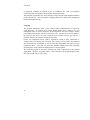
POWER SUPPLY REQUIREMENTS:
The DSPA64 requires three power supply voltages. Their functions and values are:
POWER SUPPLY REQUIREMENTS
Board function
VOLTAGE
CURRENT
digital power
+5 vdc
300 ma
analog + power
+12 vdc
100 ma
analog - power
-12 vdc
100 ma
The current requirements indicate what your supply should be capable of and not necessarily
what the board will consume in any given application. In particular, the digital requirement
will vary depending on the length of the cable connecting to the DSPHLF board.
MAXIMUM ANALOG INPUT VOLTAGE RANGE:
The absolute maximum analog input voltage range is +/- 2.75 volts. This range should not be
exceeded for proper operation of the DSPA64 board. Voltages beyond this range will lead to
incorrect and unpredictable results.
MAXIMUM ANALOG INPUT VOLTAGE RANGE
differential inputs
+/- 2.75 volts
All of the DSPA64 analog inputs are differential. This means that the absolute difference
between the + and - inputs on any given channel must be less than 2.75 volts. In addition, for
the system to work correctly, you must establish a common analog ground that is connected to
one of the screw lugs on the front edge of the board. The inputs are differential only up to the
point where the front end amplifiers saturate. When inputs float, they can easily reach
voltages that exceed the saturation levels of the input amplifiers even though their absolute
difference is still less than 2.75 volts. Connecting an analog ground reference avoids this.
41
ELECTRICAL SPECS
The default +/- 2.75 v input voltage range can be changed by modifying the resistor
attenuators at a number of points in the front end analog circuit. Refer to the warranty page
and circuit diagrams to determine which changes would be appropriate for your applications.
CALIBRATION (COUNTS PER VOLT):
Calibration refers to the number of counts per volt that an A/D system has. Generally, it is
important to know the calibration if you are doing quantitative work with your system.
No A/D converter can give exactly reproducible results on every conversion. All converters
return at best a distribution about a single central value for a given input voltage. The BB
DSP101 is no exception. In addition, components vary slightly from board to board. Users
must measure and calibrate their systems for best accuracy in a particular application and
should use the values given here only as a guide.
The following counts per volt value was developed by taking measurements with dc inputs at
.2 volt increments from 0 to 2.75 volts on a single channel with the diag.exe program. The
best fit straight line was then computed:
TYPICAL COUNTS PER VOLT
11,880 (decimal) counts per volt
TYPICAL COUNT OFFSET AT 0 INPUT VOLTS
less than +/- 20 counts
Note that the DSPA64 has no pots or other knobs for trimming the offset on a particular
channel. If offsets are important for your application, you should calibrate the system on each
channel and perform offset corrections in software.
42
DSPA64 CIRCUIT DIAGRAMS
APPENDIX B: DSPA64 CIRCUIT DIAGRAMS
The following pages have the circuit diagrams for the DSPA64 board. You should refer to
them for detailed information about power supply connections and jumper settings.
System overview......................................................................................... 45
Power supply regulators.............................................................................. 45
When reading the circuit diagrams, note that several areas around the BB INA111 have been
designed so they can be used in a variety of ways. Some of these areas are:
The BB INA111 instrument amp may be replaced with a single ended op amp. The
replacement op amp may be run in single ended or classical 4 resistor differential
mode.
The resistor attenuator pairs before and after the BB INA111 may be set to change
the input voltage range and attenuation.
The gain of the BB INA111 may be set with a resistor.
Zener diodes may be installed before the BB INA111 for additional overvoltage
protection.
The DSPA64 is shipped from the factory set to unity gain, and with all other components
selected to minimize cross talk. Changing system components will usually degrade
performance, and is not recommended unless there is no other solution.
Finally, note that an overview of the system hardware is covered in the Hardware Basics
chapter. You may wish to refer to that chapter for more information while studying the circuit
diagrams.
43
DSPA64 CIRCUIT DIAGRAMS
45
DSPHLF CIRCUIT DIAGRAMS
APPENDIX C: DSPHLF CIRCUIT DIAGRAMS
The circuit diagrams for the DSPHLF DSP32C coprocessor board are included here for
completeness. Note that the default jumper settings are also covered in the Installation chapter
of this manual. For additional information, refer to the SR DSP32C User's manual.
DSPHLF board overview............................................................................ 49
Unused gates............................................................................................... 49
47
DSPHLF CIRCUIT DIAGRAMS
49
INDEX
INDEX
Analog input voltage, maximum, 41
Application programs, 27
Calibration, 42
Circuit diagrams, DSPA64
01/14, System overview, 45
14/14, Power supply regulators, 45
Circuit diagrams, DSPHLF
01/16, Board overview, 49
16/16, Unused gates, 49
Counts per volt, 42
Default jumper settings, 4
Diagnostic utility, 39
DLL Library
DSPA64_ClearReady, 23
DSPA64_GetBaseio, 18
DSPA64_GetData, 24
DSPA64_Init, 19
DSPA64_IsReady, 23
DSPA64_SetBaseio, 18
DSPA64_Start, 22
DSPA64_Stop, 22
Helpers
DSPA64_BufferSize, 21
DSPA64_CoeffToTail, 21
DSPA64_MaximumRate, 21
DSPA64_NCountToSps, 21
DSPA64_NormalizeScale, 21
DSPA64_NTimingTicks, 21
DSPA64_SpsToNCount, 21
DSPA64_TailToCoeff, 21
Example programs, 33
Config.dsp, 38
Filter.dsp, 35
Iconfig.dsp, 37
Sample.dsp, 34
Sample18.dsp, 35
Switch.dsp, 37
Hardware basics, 9
Analog circuitry, 9
Conversion rate, 13
Digital circuitry, 12
Power supply, 14
Hardware installation, 3
Installation, 3
Default jumper settings, 4
Hardware, 3
Performance tips, 6
Software, 6
Introduction, 1
Jumper settings, default, 4
LabView Support, 29
Low level examples, 33
Power supply requirements, 14, 41
Scope24b.exe, 27
Simp24b.exe, 27
Software installation, 6
System diagnostic utility, 39
DLL Library support, 17
Electrical specs, 41
51