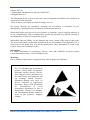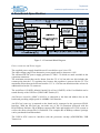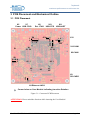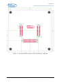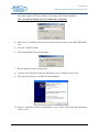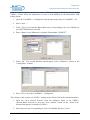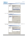
1
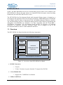
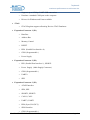
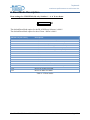
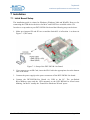
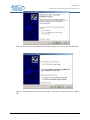
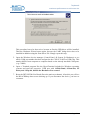
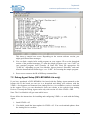
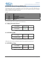
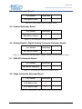
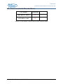
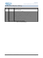
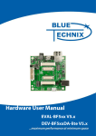
Hardware User Manual DEV-BF548-Lite DEV-BF548DA-Lite Board V1.1 Tinyboards from Bluetechnix www.bluetechnix.com Contact Bluetechnix Mechatronische Systeme GmbH Waidhausenstr. 3/19 A-1140 Vienna AUSTRIA/EUROPE [email protected] http://www.bluetechnix.com Document No.: 100-2246-1.0 Document Revision 11 2009-02-04 Blackfin DEV‐BF548‐Lite & DEV‐BF548DA‐Lite Hardware User Manual Table of Contents 1 Introduction ......................................................................................................................... 1 1.1 Overview ....................................................................................................................... 1 2 Functional Specification ...................................................................................................... 4 3 PCB Placement and Mechanical Outline............................................................................. 5 3.1 PCB Placement ............................................................................................................. 5 3.2 Mechanical Outline ....................................................................................................... 6 3.3 Extension Board Footprint ............................................................................................ 6 4 Connector Description ......................................................................................................... 8 4.1 X4 –RJ45 Ethernet Connector ...................................................................................... 8 4.2 X9 –SD-Card Connector (bottom Mount) .................................................................... 8 4.3 X6 – JTAG Bypass Connector ...................................................................................... 8 4.4 X11 – USB-UART Connectors .................................................................................... 8 4.5 X12 UART Expansion Pads ......................................................................................... 9 4.6 X1, X2, X3 Expansion Connectors ............................................................................... 9 4.7 X8, X10 – CAN1, CAN0 Connector ............................................................................ 9 4.8 X5 – Power Connector .................................................................................................. 9 4.9 Expansion Connectors ................................................................................................ 10 4.9.1 X2 – Expansion Connector 2 ............................................................................... 10 4.9.2 X1 – Expansion Connector 1 ............................................................................... 12 4.9.3 X3 – Expansion Connector 3 ............................................................................... 13 5 Switches, Jumper and LED Description ............................................................................ 16 5.1 S1 – Reset switch ........................................................................................................ 16 5.2 S2 – Ethernet Control Signals / SDCARD CS............................................................ 16 S3 – UART Switch ............................................................................................................... 16 5.3 S4 – Boot Configuration ............................................................................................. 16 5.4 JP1 – Ethernet Speed Selection................................................................................... 16 5.5 JP2 -– Power Supply Jumper ...................................................................................... 16 5.6 JP3 – RTC Power Jumper ........................................................................................... 17 5.7 JP4 – USB ID .............................................................................................................. 17 5.8 S5 - Button .................................................................................................................. 17 5.9 General Purpose LEDs ................................................................................................ 17 5.10 Ethernet LEDs ......................................................................................................... 17 5.11 LEDs of the Debug Agent ....................................................................................... 17 6 Boot Mode Description ..................................................................................................... 18 Blackfin DEV‐BF548‐Lite & DEV‐BF548DA‐Lite Hardware User Manual 7 Installation ......................................................................................................................... 19 7.1 Initial Board Setup ...................................................................................................... 19 7.2 Debug Agent Setup (DEV-BF548DA-Lite only) ....................................................... 22 8 Using the VDSP Flash Programming Tool ....................................................................... 27 8.1 Developing an Application ......................................................................................... 27 8.2 Overwriting BLACKSheep Code ............................................................................... 27 9 Extender Board Compatibility List.................................................................................... 28 9.1 Without Extender Board ............................................................................................. 28 9.2 EXT-BF5xx-EXP ........................................................................................................ 28 9.3 EXT-BF5xx-Video ..................................................................................................... 28 9.4 Audio Extender Board ................................................................................................ 29 9.5 Camera Extender Board .............................................................................................. 29 9.6 Analog-Digital / Digital-Analog Converter Extender Board ...................................... 29 9.7 USB-ETH Extender Board ......................................................................................... 29 9.8 Video and Audio Extender Board ............................................................................... 29 9.9 Camera and Audio Extender Board ............................................................................ 30 10 Anomalies....................................................................................................................... 31 11 Product Changes ............................................................................................................. 32 12 Document Revision History ........................................................................................... 33 A List of Figures and Tables ................................................................................................. 34 Blackfin DEV‐BF548‐Lite & DEV‐BF548DA‐Lite Hardware User Manual Packing List The DEV-BF548DA-Lite and the DEV-BF548-Lite Board Package contain the following items: 1. DEV-BF548DA-Lite or DEV-BF548-Lite Board 2. 1x USB Cable (USB A/B) 3. 1x USB Cable (USB A/B) (DEV-BF548DA-Lite only) 4. 1x USB Cable (USB A/Mini USB) 5. 1x Ethernet Cable 6. 1x Power Supply. 7. Support CD Note: The Core Modules are not shipped with the board, so you must order them separately. Blackfin DEV‐BF548‐Lite & DEV‐BF548DA‐Lite Hardware User Manual Edition 2007-02 © Bluetechnix Mechatronische Systeme GmbH 2007 All Rights Reserved. The information herein is given to describe certain components and shall not be considered as a guarantee of characteristics. Terms of delivery and rights of technical change reserved. We hereby disclaim any warranties, including but not limited to warranties of noninfringement, regarding circuits, descriptions and charts stated herein. Bluetechnix makes and you receive no warranties or conditions, express, implied, statutory or in any communication with you. Bluetechnix specifically disclaims any implied warranty of merchantability or fitness for a particular purpose. Bluetechnix takes no liability for any damages and errors causing of the usage of this board. The user of this board is responsible by himself for the functionality of his application. He is allowed to use the board only if he has the qualification. More information is found in the General Terms and Conditions (AGB). Information For further information on technology, delivery terms and conditions and prices please contact Bluetechnix (http://www.bluetechnix.com). Warnings Due to technical requirements components may contain dangerous substances. The Core Modules and development systems contain ESD (electrostatic discharge) sensitive devices. Electrostatic charges readily accumulate on the human body and equipment and can discharge without detection. Permanent damage may occur on devices subjected to high-energy discharges. Proper ESD precautions are recommended to avoid performance degradation or loss of functionality. Unused Core Modules and Development Boards should be stored in the protective shipping package. Blackfin DEV‐BF548‐Lite & DEV‐BF548DA‐Lite Hardware User Manual BLACKFIN Products Core Modules: CM-BF533: Blackfin Processor Module powered by Analog Devices single core ADSP-BF533 processor; up to 600MHz, 32MB RAM, 2MB Flash, 120 pin expansion connector and a size of 36.5x31.5mm CM-BF537E: Blackfin Processor Module powered by Analog Devices single core ADSP-BF537 processor; up to 600MHz, 32MB RAM, 4MB Flash, integrated TP10/100 Ethernet physical transceiver, 120 pin expansion connector and a size of 36.5x31.5mm CM-BF537U: Blackfin Processor Module powered by Analog Devices single core ADSP-BF537 processor; up to 600MHz, 32MB RAM, 4MB Flash, integrated USB 2.0 Device, 120 pin expansion connector and a size of 36.5x31.5mm (will be replaced by CM-BF527). TCM-BF537: Blackfin Processor Module powered by Analog Devices single core ADSP-BF537 processor; up to 500MHz, 32MB RAM, 8MB Flash, 28x28mm, 120 pin expansion connector, Ball Grid Array or Border Pads for reflow soldering, industrial temperature range -40°C to +85°C. CM-BF561: Blackfin Processor Module powered by Analog Devices dual core ADSP-BF561 processor; up to 2x 600MHz, 64MB RAM, 8MB Flash, 120 pin expansion connector and a size of 36.5x31.5mm. CM-BF527: The new Blackfin Processor Module is powered by Analog Devices single core ADSP-BF527 processor; key features are USB OTG 2.0 and Ethernet. The 2x60 pin expansion connectors are backwards compatible with other Core Modules. CM-BF548: The new Blackfin Processor Module is powered by Analog Devices single core ADSP-BF548 processor; key features are 64MB DDR SD-RAM 2x100 pin expansion connectors. Development Boards: EVAL-BF5xx: Low cost Blackfin processor Evaluation Board with one socket for any Bluetechnix Blackfin Core Module. Additional peripherals are available, such as an SD-Card. DEV-BF5xxDA-Lite: Get ready to program and debug Bluetechnix Core Modules with this tiny development platform including a USB Based Debug Agent. The DEV-BF5xxDA-Lite is a low cost starter development system including VDSP++ Evaluation Software License. Blackfin DEV‐BF548‐Lite & DEV‐BF548DA‐Lite Hardware User Manual DEV-BF5xx-FPGA: Blackfin Development Board with two sockets for any combination of Blackfin Core Modules. Additional peripherals are available, such as SD-Card, Ethernet, USB host, multi-port JTAG including a USB based Debug Agent, connector for an LCD-TFT Display and connector for a digital camera system. A large on-board SPARTAN-3 FPGA and Soft IPs make this board the most flexible Blackfin development platforms ever developed. DEV-BF548DA-Lite: Get ready to program and debug Bluetechnix CM-BF548 Core Module with this tiny development platform including a USB Based Debug Agent. The DEV-BF548DA-Lite is a low cost starter development system including VDSP++ Evaluation Software License. EXT-Boards: The following Extender Boards are available: EXT-BF5xx-Audio, EXT-BF5xx-Video, EXT-BF5xx-Camera, EXT-BF5xx-Exp, EXTBF5xx-ETH-USB, EXT-BF5xx-AD/DA. Additional boards based on customer request are also available. Software Support: BLACKSheep: The BLACKSheep VDK is a multithreaded framework for the Blackfin processor family from Analog Devices that includes driver support for a variety of hardware extensions. It is based on the realtime VDK kernel included within the VDSP++ development environment. LabVIEW: LabVIEW embedded support for the CM-BF537E, CM-BF537U and TCM-BF537 Core Modules is based upon the BLACKSheep VDK driver Framework. uClinux: All the Core Modules are fully supported by uClinux. The required boot loader and uClinux can be downloaded from: http://blackfin.uClinux.org. Upcoming Products and Software Releases: Keep up-to-date with all the changes to the Bluetechnix product line and software updates at: www.bluetechnix.com BLACKFIN Design Service Based on more than five years of experience with Blackfin, Bluetechnix offers development assistance as well as custom design services and software development. Blackfin DEV‐BF548‐Lite & DEV‐BF548DA‐Lite Hardware User Manual Tinyboards maximum performance at minimum size 1 Introduction NOTE: The DEV-BF548DA-Lite has an on-board Debug Agent, which is not available on the DEV-BF548-Lite Board. All other features are identical! In this document, when describing both boards, the name DEV-BF548-Lite is used. The DEV-BF548-Lite Development Board with integrated Debug Agent is designed as a development and application board for the high performance ADSP-BF548 based CM-BF548 Core Module. Special feature of the board is the 10/100Mbit industrial Ethernet controller. The integrated Debug Agent is a USB based debug interface which enables programming and debugging of the Blackfin Core Modules. It is fully compatible with the Visual DSP++ development environment. The development board provides all interfaces on dedicated connectors or expansion connectors. Extender boards can be plugged on top of the Development Board in order to enable additional interfaces. 1.1 Overview The DEV-BF548-Lite Board includes the following components: 60 Pin Expansion Connector 1 DC/DC Power Supply USB to UART DEBUG AGENT SD-Card (5V and 3V3) CM-BF548 USB-OTG 64MB DDR SD RAM 8MB Flash 10/100Mbit (Ethernet Controller) CAN 60 Pin Expansion Connector 2 Figure 1-1: Overview of the DEV-BF548-Lite Board DC/DC Converters o 5V@2A o [email protected] (draws its power from the 5V output of the DC/DC) 1 Core Module Slot o Supports the CM-BF548 Core Module USB-to-UART Port Blackfin DEV‐BF548‐Lite & DEV‐BF548DA‐Lite Hardware User Manual Page 1 Tinyboards maximum performance at minimum size o Supports up to 915kbps UART-USB conversion. o Emulates a standard COM port on the computer. o Drivers for Windows and Linux available JTAG o JTAG-Plug that supports all analog Devices JTAG Emulators. Expansion Connector 1 (X1) o Data Bus o Address Bus o Memory Control o RESET o PPI0 (Parallel Port Interface 0) o GPIO (Programmable ) o Power Supply Expansion Connector 2 (X2) o PPI1 (Parallel Port Interface 1), SPORT1 o Power Supply (Main Supply Connector) o GPIO (Programmable ) o UART0 o SPI2 Expansion Connector 3 (X3) o ATAPI Interface o SPI0, SPI1 o SPORT2, SPORT3 o CAN 0, CAN1 o UART2, UART3 o PPI0 (Sync, D16,D17)) o SDIO Interface o GPIO (Programmable ) Blackfin DEV‐BF548‐Lite & DEV‐BF548DA‐Lite Hardware User Manual Page 2 Tinyboards maximum performance at minimum size USB2.0 OTG Connector o Uses the On-Board USB-OTG transceiver RJ-45 Ethernet Plug o Connected to the On-Board SMSC LAN9218 Ethernet Controller External Power Supply o The board is shipped with a 12V, 2A external DC/DC Power Supply Blackfin DEV‐BF548‐Lite & DEV‐BF548DA‐Lite Hardware User Manual Page 3 Tinyboards maximum performance at minimum size 2 Functional Specification Figure 2-1: Functional Block Diagram Power connector and Power supply: The supplied power supply should be used. It can deliver up to 2A at 12V. The input voltage range of an alternative power supply must be between 6-16V! The on-board DC/DC power supply generates 5V and 3.3V which are made available at the expansion connectors. The maximum current that can be drawn from the 5V is 2A, but take care this includes the current going into the 3.3V regulator also, because this regulator is powered by the 5V. The maximum current that can be drawn from the 3.3V is 1.5A but note that this means at least 1A additional load on the 5V connector. The serial Port 0 (UART0, default Console IO) or Port1 (UART1) of the Core Module can be routed directly to the USB Port (USB/UART Switch (S3). An Ethernet controller (SMSC LAN9218) is connected to the data and address bus on the baseboard providing a high speed 10/100MBit LAN Interface An SD-Card connector is mounted on the board and is connected to the processors SD-IO Interface. With the SD-Card one can make use of file IO Functions delivered with the BLACKSheep Software. BLACKSheep supports SD-Cards and includes a FAT file system as well as the most relevant File IO Functions. The complete BLACKSheep software package can be purchased from Bluetechnix. The USB2.0 OTG connector interfaces with the processors on-chip (ADSP-BF548) USB Transceiver. Blackfin DEV‐BF548‐Lite & DEV‐BF548DA‐Lite Hardware User Manual Page 4 Tinyboards maximum performance at minimum size 3 PCB Placement and Mechanical Outline 3.1 PCB Placement X5 X7 Power USB JTAG X6 Ext. JTAG S4 1 0 JP4 3 P J 2 P J 1…8 X1 31 30 S1 S2 1 …4 0 1 X13 X11 USB-OTG USB-UART S3 ON X2 31 30 60 1 X12 1 0 1 1 X10 CAN1 X8 CAN0 60 1 80 1 X3 41 40 X9 SD-CARD 1 P J S5 X4 Ethernet JACK Corner holes on Core Module indicating insertion Rotation Figure 3-1: Connector PCB Placement ATTENTION: Please mind the direction while inserting the Core Module! Blackfin DEV‐BF548‐Lite & DEV‐BF548DA‐Lite Hardware User Manual Page 5 Tinyboards maximum performance at minimum size 3.2 Mechanical Outline Figure 3-2: Mechanical Outline – Expansion Connector Placement 3.3 Extension Board Footprint If you want to design your own Extension Board for the DEV-BF548, you can use the following Board dimensions. The mating Connectors in Figure 3-3 are mounted on top. Blackfin DEV‐BF548‐Lite & DEV‐BF548DA‐Lite Hardware User Manual Page 6 Tinyboards maximum performance at minimum size Figure 3-3: Recommended Footprint for Extension Boards – top view Blackfin DEV‐BF548‐Lite & DEV‐BF548DA‐Lite Hardware User Manual Page 7 Tinyboards maximum performance at minimum size 4 Connector Description 4.1 X4 –RJ45 Ethernet Connector Pin No. 1 2 3 4 5 6 7 8 Signal (Core Module) TX+ TX‐ RX+ NC NC RX‐ NC NC IO‐Type O O I ‐ ‐ I ‐ ‐ Table 4-1: Ethernet Connector 4.2 X9 –SD-Card Connector (bottom Mount) Pin No. 0 1 2 3 4 5 6 7 8 9 10 Signal (Core Module) SD_D2 SD_D3 SD_CMD GND 3,3V SD_CLK GND SD_D0 SD_D1 ‐ ‐ Description (SD Card) DAT2 CD/DAT3 CMD VSS1 VDD CLK VSS2 DAT0 DAT1 CD WP Table 4-2: SD-Card Connector 4.3 X6 – JTAG Bypass Connector The JTAG connector is compliant with any Blackfin JTAG Emulator from Analog Devices. When an external JTAG emulator is attached the on-board JTAG is bypassed and the external one is automatically used. 4.4 X11 – USB-UART Connectors Connects either UART0 (when S3 is in Pos 1) or UART1 (when S3 is in Pos 0) to the USB Interface enabling a COM Port on the PC. UART0 is standard console IO for the BLACKSheep Software. Blackfin DEV‐BF548‐Lite & DEV‐BF548DA‐Lite Hardware User Manual Page 8 Tinyboards maximum performance at minimum size 4.5 X12 UART Expansion Pads When S3 is in position 1 the UART1 on PortH (TX, RX) is available on the expansion pins and disconnected from the USB-UART Chip. Pin No. Signal Signal Type 1 2 3 4 TxD Blackfin RxD Blackfin GND 3V3 Input Core Module Output Core Module Regulated Power Table 4-3: UART1 additional Header 4.6 X1, X2, X3 Expansion Connectors The Expansion Connectors on the DEV-BF548-Lite for a Stacked Height of 16mm are of the following type: Part Manufacturer Manufacturer Part Nr. X1, X2 Matching connector X3 Matching connector AMP (Stacked Height = 16mm) AMP AMP (Stacked Height = 16mm) AMP 5‐5179010‐2 5179031‐2 5‐5179010‐3 5179031‐3 Table 4-4: DEV-board connector types The matching connector, which is used for building an extender board, can be ordered from Bluetechnix. 4.7 X8, X10 – CAN1, CAN0 Connector Pin No. Signal (Core Module) IO‐Type 1 2 CAN+ CAN‐ I/O I/O Table 4-5: CAN Connector 4.8 X5 – Power Connector The board is shipped with a 12V, 2A external DC/DC Power Supply which should be used. Pin No. Signal Description 1 2 3 Vin (+6V to +16V DC) Input Supply NC GND Preferable 12V DC (2A) Table 4-6: Power Supply Blackfin DEV‐BF548‐Lite & DEV‐BF548DA‐Lite Hardware User Manual Page 9 Tinyboards maximum performance at minimum size Figure 4-1: Power connector To connect to X141 use a “DCPP1” e.g. from Cliff Electronic Components (2.1mm * 5.5mm * 9.5mm) plug to the power supply. Outer contact is GND, inner contact is VCC. 4.9 Expansion Connectors The interface to the extender boards is grouped into three different connectors (X1, X2, X3). The three tables below shows the pin out of these three connectors. The column “Pin No. (Connector)” shows the pin number of each connector, while the column “Pin No. (Symbol) shows the pin number of the extension connector schematic symbol, where the pins are numbered from 1 to 200. The column “Pin No. CM” represents the pin number of the corresponding signal on the Core Module. 4.9.1 X2 – Expansion Connector 2 Pin No. (Symbol) Pin No. (Connector) Signal Signal type Pin No CM 1 2 3 4 5 6 7 8 9 10 11 12 13 14 15 16 17 18 19 20 21 22 23 24 25 26 1 2 3 4 5 6 7 8 9 10 11 12 13 14 15 16 17 18 19 20 21 22 23 24 25 26 PC7 PC6 PC3 PC2 CLKOUT PE15 PA13 PA5 3.3V 3.3V PD0 PD2 PD4 PD6 PD8 PD10 PD12 PD14 PH0 PE12 PB11 PB9 PE8 PB13 PB12 PH1 I/O I/O I/O I/O O I/O I/O I/O PWR PWR I/O I/O I/O I/O I/O I/O I/O I/O I/O I/O I/O I/O I/O I/O I/O I/O 93 94 97 98 70 185 114 106 135 137 139 141 143 145 147 149 22 188 130 128 192 132 131 23 Blackfin DEV‐BF548‐Lite & DEV‐BF548DA‐Lite Hardware User Manual Page 10 Tinyboards maximum performance at minimum size 27 28 29 30 31 32 33 34 35 36 37 38 39 40 41 42 43 44 45 46 47 48 49 50 51 52 53 54 55 56 57 58 59 60 27 28 29 30 31 32 33 34 35 36 37 38 39 40 41 42 43 44 45 46 47 48 49 50 51 52 53 54 55 56 57 58 59 60 nARDY PH4 5.0V *) 5.0V 2) Vin 3) Vin 3) PH7 nAMS3 nABE1 nABE0 PB14 PE7 PB8 PB10 PE11 PE13 PD15 PD13 PD11 PD9 PD7 PD5 PD3 PD1 GND GND PA1 PA9 PH3 PE14 PC1 PC0 PC5 PC4 I I/O PWR PWR PWR PWR I/O O O O I/O I/O I/O I/O I/O I/O I/O I/O I/O I/O I/O I/O I/O I/O PWR PWR I/O I/O I/O I/O I/O I/O I/O I/O 21 26 29 32 17 16 133 193 127 129 189 187 150 148 146 144 142 140 138 136 102 110 25 186 99 100 95 96 4-7 Expansion Connector X2 1) Maximum current carrying capacity: 1A. 2) Pin 29 and 30 of the X8 connector are +5V stabilized from the DC/DC that can be used for custom add-on boards or the extender boards. Maximum current carrying capacity: 900mA.(Attention: If Core Modules with USB in host mode are used, the current must be shared with the connected USB device. 3) Pin 31 and 32 of the X7 are Vin of the external power supply minus the input protection diode voltage. These pins can be used for custom add-on board power supplies. Maximum current carrying capacity: 1A. Blackfin DEV‐BF548‐Lite & DEV‐BF548DA‐Lite Hardware User Manual Page 11 Tinyboards maximum performance at minimum size 4.9.2 X1 – Expansion Connector 1 Pin No. (Symbol) Pin No. (Connector) Signal Signal type Pin No CM 61 62 63 64 65 66 67 68 69 70 71 72 73 74 75 76 77 78 79 80 81 82 83 84 85 86 87 88 89 90 91 92 93 94 95 96 97 98 99 100 101 102 103 104 105 1 2 3 4 5 6 7 8 9 10 11 12 13 14 15 16 17 18 19 20 21 22 23 24 25 26 27 28 29 30 31 32 33 34 35 36 37 38 39 40 41 42 43 44 45 A1 A3 A5 A7 A9 A11 A13 A15 PG1 PG2 PF1 PF3 PF5 PF7 PF9 PF11 PF13 PF15 GND nAMS1 nAWE nNMI D0 D2 D4 D6 D8 D10 D12 D14 D15 D13 D11 D9 D7 D5 D3 D1 nRESET nAOE nARE nAMS2 3.3V PF14 PF12 O O O O O O O O I/O I/O I/O I/O I/O I/O I/O I/O I/O I/O PWR O O I I/O I/O I/O I/O I/O I/O I/O I/O I/O I/O I/O I/O I/O I/O I/O I/O I/O O O O PWR I/O I/O 1 3 5 7 9 11 13 15 165 164 181 179 177 175 173 171 169 167 30 20 34 35 37 39 41 43 45 47 49 50 48 46 44 42 40 38 36 67 18 19 31 168 170 Blackfin DEV‐BF548‐Lite & DEV‐BF548DA‐Lite Hardware User Manual Page 12 Tinyboards maximum performance at minimum size 106 107 108 109 110 111 112 113 114 115 116 117 118 119 120 46 47 48 49 50 51 52 53 54 55 56 57 58 59 60 PF10 PF8 PF6 PF4 PF2 PF0 PH2 PG0 A14 A12 A10 A8 A6 A4 A2 I/O I/O I/O I/O I/O I/O I/O I/O O O O O O O O 172 174 176 178 180 182 24 166 14 12 10 8 6 4 2 4-8 Expansion Connector X1 4.9.3 X3 – Expansion Connector 3 Pin No. (Symbol) Pin No. (Connector) Signal Signal type Pin No CM 121 122 123 124 125 126 127 128 129 130 131 132 133 134 135 136 137 138 139 140 141 142 143 144 145 146 1 2 3 4 5 6 7 8 9 10 11 12 13 14 15 16 17 18 19 20 21 22 23 24 25 26 GND PJ13 PJ12 PJ11 PJ10 PJ9 PJ8 PJ7 PJ6 PJ5 PJ4 PJ3 PJ2 PJ1 GND PB0 PB1 PB2 PB3 PB4 PB5 PB6 PB7 GND PA0 PA2 PWR I/O I/O I/O I/O I/O I/O I/O I/O I/O I/O I/O I/O I/O PWR I/O I/O I/O I/O I/O I/O I/O I/O PWR I/O I/O 74 75 76 77 78 79 80 81 82 83 84 85 86 119 120 121 122 123 124 125 126 101 103 Blackfin DEV‐BF548‐Lite & DEV‐BF548DA‐Lite Hardware User Manual Page 13 Tinyboards maximum performance at minimum size 147 148 149 150 151 152 153 154 155 156 157 158 159 160 161 162 163 164 165 166 167 168 169 170 171 172 173 174 175 176 177 178 179 180 181 182 183 184 185 186 187 188 189 190 191 192 193 194 195 27 28 29 30 31 32 33 34 35 36 37 38 39 40 41 42 43 44 45 46 47 48 49 50 51 52 53 54 55 56 57 58 59 60 61 62 63 64 65 66 67 68 69 70 71 72 73 74 75 PA3 PA4 PA6 PA7 PA8 PA10 PA11 PA12 PA14 PA15 GND GND 3.3V 3.3V 5.0V Vin GND PG3 PG4 PG5 PG6 PG7 PG8 PG9 PG10 PG11 PG12 PG13 PG14 PG15 GND PE0 PE1 PE2 PE3 PE4 PE5 PE6 PE9 PE10 GND PC8 PC9 PC10 PC11 PC12 PC13 PH6 PH5 I/O I/O I/O I/O I/O I/O I/O I/O I/O I/O PWR PWR PWR PWR PWR PWR PWR I/O I/O I/O I/O I/O I/O I/O I/O I/O I/O I/O I/O I/O PWR I/O I/O I/O I/O I/O I/O I/O I/O I/O PWR I/O I/O I/O I/O I/O I/O I/O I/O Blackfin DEV‐BF548‐Lite & DEV‐BF548DA‐Lite Hardware User Manual 104 105 107 108 109 111 112 113 115 116 163 162 161 160 159 158 157 156 155 154 153 152 151 200 199 198 197 196 195 194 191 190 92 91 90 89 88 87 28 27 Page 14 Tinyboards maximum performance at minimum size 196 197 198 199 200 76 77 78 79 80 ATAPI_PDIAG EXT_WAKEUP GND CLKBUF GND I O PWR O PWR 134 33 69 4-9 Expansion Connector X3 Blackfin DEV‐BF548‐Lite & DEV‐BF548DA‐Lite Hardware User Manual Page 15 Tinyboards maximum performance at minimum size 5 Switches, Jumper and LED Description 5.1 S1 – Reset switch Performs system reset. 5.2 S2 – Ethernet Control Signals / SDCARD CS Default Settings Dipswitch Function S2.1 S2.2 S2.3 S2.4 Connect SDCARD CS to PC5 Connect nAMS1 from Core Module to Ethernet chip Connect PE6 from Core Module to Ethernet chip IRQ Connect PME of Ethernet chip to test point PME1 5-1 DIP switch S2 S3 – UART Switch Move S3 to position 1 to route the Core Modules RX0 and TX0 signals to USB Move S3 to position 0 to route the Core Modules RX1 and TX1 signals to USB 5.3 S4 – Boot Configuration S4.1 to S4.4 Control the boot mode and are described in chapter 6 Boot Mode Description. Dipswitch Function S4.1 S4.2 S4.3 S4.4 S4.5 S4.6 S4.7 S4.8 Bootmode 0 Bootmode 1 Bootmode 2 Bootmode 3 Power Supply for CAN0 Driver IC Power Supply for CAN1 Driver IC Connect TXD‐USB to VCC Connect S5 to VCC 5-2 DIP switch S4 5.4 JP1 – Ethernet Speed Selection Set jumper JP1 to select Ethernet Speed 10MBit/s and unset JP1 for 100Mbit/s. 5.5 JP2 -– Power Supply Jumper This jumper can be removed in order to insert an AMPERE METER for current measurement: Blackfin DEV‐BF548‐Lite & DEV‐BF548DA‐Lite Hardware User Manual Page 16 Tinyboards maximum performance at minimum size 5.6 JP3 – RTC Power Jumper This jumper is used to connect the VddRTC pin of the Core Module to 3.3V. You can also use this jumper to connect a battery to the internal RTC of the Blackfin.´ 5.7 JP4 – USB ID Short jumper JP4 to tie USB ID to GND on the USB-OTG Connector X13. 5.8 S5 - Button The button S5 is a GPIO Button and connects to PH7. 5.9 General Purpose LEDs Designator Function Blackfin GPIO V14 V15 GPIO LED GPIO LED PH6 PH5 Table 5-3: Core Module LEDs 5.10 Ethernet LEDs Designator Color Description V1 V2 V3 Yellow Green Green Fullduplex Activity 100MB Speed LED Table 5-4: Ethernet LEDs 5.11 LEDs of the Debug Agent Designator Color Description V9 V10 V11 V12 Green Green Green Green Flag0 Flag1 Monitor Pr. done Table 5-5: LEDs for the Debug Agent Blackfin DEV‐BF548‐Lite & DEV‐BF548DA‐Lite Hardware User Manual Page 17 Tinyboards maximum performance at minimum size 6 Boot Mode Description Boot-settings for CM-BF548 (S4) only Switches 1 – 4 of 8 are shown The default Boot Mode option for the BLACKSheep Software is 0001 ! The default Boot Mode option for the uClinux / uBoot is 0001 ! BMODE3–0 (S4.4‐S4.1) Description 0000 0001 0010 0011 0100 0101 0110 0111 1000 1001 1010 1011 1100 1101 1110 1111 Idle–no boot Boot from 8‐ or 16‐bit external flash memory Boot from 16‐bit asynchronous FIFO Boot from serial SPI memory (EEPROM or flash) Boot from SPI host device Boot from serial TWI memory (EEPROM/flash) Boot from TWI host Boot from UART host Reserved Reserved Boot from (DDR) SDRAM Boot from OTP memory Reserved Boot from 8‐ or 16‐bit NAND flash memory via NFC Boot from 16‐Bit Host DMA Boot from 8‐Bit Host DMA Table 6-1: Boot modes Blackfin DEV‐BF548‐Lite & DEV‐BF548DA‐Lite Hardware User Manual Page 18 Tinyboards maximum performance at minimum size 7 Installation 7.1 Initial Board Setup The installation guide is written for Windows (Windows 2000 and WinXP). However for connecting the USB device the driver for MAC and LINUX are available on the CD. In order to set up und test your DEV-BF548-Lite board the following steps can be done: 1. Make sure jumpers JP2 and JP3 are set and the Switch S3 is in Position 1. as shown in Figure 7-1 (JP1 unset). Figure 7-1: Setup of the DEV-BF548-Lite Board 2. If you want to use an SD-Card, insert the SD-Card in the appropriate slot at the bottom side of the board. 3. Connect the power supply to the power connector off the DEV-BF548-Lite board. 4. Connect the DEV-BF548-Lite Board via USB to the PC. The pre-flashed BLACKSheep starts and the LED mounted on the DEV-BF548-Lite board starts blinking. On the PC usually the ‘Found New Hardware Wizard’ opens. Blackfin DEV‐BF548‐Lite & DEV‐BF548DA‐Lite Hardware User Manual Page 19 Tinyboards maximum performance at minimum size If the wizard asks you to connect to the windows update site, select “No, not this time” Choose: “Install from a list or specific location”. The driver is located on your support CD. Blackfin DEV‐BF548‐Lite & DEV‐BF548DA‐Lite Hardware User Manual Page 20 Tinyboards maximum performance at minimum size This procedure has to be done twice, because at first the USB driver will be installed. Then the Hardware Wizard opens again, because the UART bridge driver has to be installed in addition using the same driver file. Simply repeat this step. 5. Open the Windows device manager (Control Panel Æ System Æ Hardware) to see which COM port number has been assigned to the CP2101 UART-to-USB Chip. This number differs from computer to computer based on the already installed COM ports. (e.g. COM4) 6. Open a Terminal program like the HyperTerminal included in Windows operating systems and open the respective COM port with 115200 Baud, 8 Data-bits, No Parity and 1 Stop bit, disable the Hardware flow control. 7. Reset the DEV-BF548-Lite Board (Press the main reset button). After this you will see the BLACKSheep boot-screen showing up. If you disconnect the device, you have to reconnect. Blackfin DEV‐BF548‐Lite & DEV‐BF548DA‐Lite Hardware User Manual Page 21 Tinyboards maximum performance at minimum size This shows a sample boot screen. Depending on the current software version, you might get different boot messages. 8. You can find a simple hello world program on your support CD or at the download section of the product homepage. To start the sample program, type “xmr UART” on your terminal program, then (Transfer Æ Send file) select the appropriate file “UART.ldr” depending on your Core Module, choose protocol “Xmodem” and send. After the download has finished type “exec UART” for executing the sample program. 9. Press reset to return to the BLACKSheep command line. 7.2 Debug Agent Setup (DEV-BF548DA-Lite only) If you have purchased a DEV-BF548DA-Lite board with the Debug Agent mounted on the bottom side of the board you can use it to download and debug your software with the VDSP++ development environment from Analog Devices. An evaluation version is included in the support CD or you can download it from our website or the website from Analog Devices. Currently the Debug Agent works only with version 4.5 of the VDSP++ IDE. Note: The Core Module will get warm while in use. Please follow the instructions for installing and configuring VDSP++ to work with the Debug Agent. 1. Install VDSP++4.5 2. If available install the latest update for VDSP++4.5. You can download updates from the Analog Devices website. Blackfin DEV‐BF548‐Lite & DEV‐BF548DA‐Lite Hardware User Manual Page 22 Tinyboards maximum performance at minimum size 3. Configure VDSP++4.5 to support the DEV-BF548DA-Lite by starting the Installer from your support CD. Once started you should see the following dialog. Note: To run the installer the .net framework is required! 4. Select the Core Module that you have inserted in the socket of your DEV-BF548DALite. 5. Press the “Install” button. 6. You should get the following message: 7. Be sure that the board is powered on! 8. Connect X4 (USB JTAG) with an USB cable to a free USB port on your PC. 9. The following dialog or a similar one should appear: 10. Choose “Install the software automatically”, press “Next” and follow the instructions on the screen. Blackfin DEV‐BF548‐Lite & DEV‐BF548DA‐Lite Hardware User Manual Page 23 Tinyboards maximum performance at minimum size After the install process you have to create a Platform using the Platform Wizard of the VDSP++. Please follow the instructions to create a valid Platform for the Bluetechnix USB Debug Agent. 1. Open the VisualDSP++ Configurator from the start menu entry of VisualDSP++ 4.5. 2. Select “New…” 3. In the “Type” box select the Bluetechnix entry corresponding to the Core Module on your DEV-BF548DA-Lite board. 4. Enter a Name for the Platform for example “Bluetechnix CM-BF537”. 5. Select “Ok”. The created platform should appear in the “Platforms” section of the “configurator” window. 6. Press “Ok” to close the VisualDSP++ Configurator. The last step is the creation of a VDSP++ debug session. Please follow the instructions below. 1. Open the “New Session Wizard” from the pulldown menu of the VDSP++ (SessionÆNew Session) or press the “New Session” button on the “Sesson List” window that appears on startup of VDSP++. 2. Select the processor corresponding to your Core Module and press “Next”. Blackfin DEV‐BF548‐Lite & DEV‐BF548DA‐Lite Hardware User Manual Page 24 Tinyboards maximum performance at minimum size 3. Select “EZ-KIT Lite” and press “Next”. 4. Select the platform that you have created with the VisualDSP++ Configurator and press “Finish”. Blackfin DEV‐BF548‐Lite & DEV‐BF548DA‐Lite Hardware User Manual Page 25 Tinyboards maximum performance at minimum size Now the session is ready and VDSP++ should start with these settings. The Core Module on the DEV-BF548DA-Lite is now ready for debugging. For further information about the session wizard and the VDSP++ tools please refer to the VDSP++ manuals downloadable from the Analog Devices website. If you change your Core Module on the DEV-BF548DA-Lite you have to reconfigure VDSP++ starting with the install tool as described above. Blackfin DEV‐BF548‐Lite & DEV‐BF548DA‐Lite Hardware User Manual Page 26 Tinyboards maximum performance at minimum size 8 Using the VDSP Flash Programming Tool 8.1 Developing an Application If you are developing your own projects with the VDSP++ development tools using the JTAG provided by Analog Devices you can use the flash programming tool included in the VDSP++ environment in order to flash your program on the Core Module. You have to load the flash driver located on your EVAL board support CD corresponding to the inserted Core Module. 8.2 Overwriting BLACKSheep Code If you overwrite intentionally or unintentionally the section in the flash containing the BLACKSheep code, you need a JTAG device and the VDSP++ flash tool to reprogram the flash. Flashing the appropriate BLACKSheep loader file (*.ldr) located on the CD, reinstalls the BLACKSheep code. The examples, drivers and the BLACKSheep software are under permanent development. Please refer to the download section of www.bluetechnix.com to get the latest versions or updates. Blackfin DEV‐BF548‐Lite & DEV‐BF548DA‐Lite Hardware User Manual Page 27 Tinyboards maximum performance at minimum size 9 Extender Board Compatibility List This chapter points out the compatibility of the DEV-BF548-Lite and DEV-BF548DA-Lite with Core Module and Extension Boards. Please refer to the Extender board and Core Module Hardware Manuals for further information. Legend: OK (OK) NO NG NT Limited Full functional Functional but not all features are available Not functional Functionality not guaranteed Not tested yet Limited The following tables show possible board combinations: 9.1 Without Extender Board Core Module CM-BF548 No Extender OK Table 9-1: Used without Extender Board 9.2 EXT-BF5xx-EXP Core Module CM-BF548 EXT-BF5xx-EXP NT Table 9-2: Used with the Experimental Extender Board All boards can be used in combination with the Experimental Extender Board 9.3 EXT-BF5xx-Video Core Module CM-BF548 EXT-BF5xx-Video NT Table 9-3: Used with the Video Extender Board Blackfin DEV‐BF548‐Lite & DEV‐BF548DA‐Lite Hardware User Manual Page 28 Tinyboards maximum performance at minimum size 9.4 Audio Extender Board Core Module CM-BF548 EXT-BF5xx-Audio NT Table 9-4: Used with the Audio Extender Board 9.5 Camera Extender Board Core Module CM-BF548 EXT-BF5xx-Camera NT Table 9-5: Used with the Camera Extender Board 9.6 Analog-Digital / Digital-Analog Converter Extender Board Core Module CM-BF548 EXT-BF5xx-AD/DA NT Table 9-6: Used with the Analog-Digital / Digital-Analog Converter Extender Board 9.7 USB-ETH Extender Board Core Module CM-BF548 EXT-BF5xx-USB-ETH NT Table 9-7: Used with the USB-ETH Extender Board 9.8 Video and Audio Extender Board Core Module CM-BF548 EXT-BF5xx-Video NT EXT-BF5xx-Audio NT Table 9-8: Used with the Video and the Audio Extender Board Blackfin DEV‐BF548‐Lite & DEV‐BF548DA‐Lite Hardware User Manual Page 29 Tinyboards maximum performance at minimum size 9.9 Camera and Audio Extender Board Core Module CM-BF548 EXT-BF5xx-Camera NT EXT-BF5xx-Audio NT Table 9-9: Used with the Camera and the Audio Extender Board Blackfin DEV‐BF548‐Lite & DEV‐BF548DA‐Lite Hardware User Manual Page 30 Tinyboards maximum performance at minimum size 10 Anomalies 2 1 Missing pull up resistor on nBR -> workaround done Missing pull up resistor on CMD_OD -> workaround done Table 10-1: Anomalies on V1.0 boards Blackfin DEV‐BF548‐Lite & DEV‐BF548DA‐Lite Hardware User Manual Page 31 Tinyboards maximum performance at minimum size 11 Product Changes Version V1.1 V1.0 Changes Bug Fix and Connector Replacement Initial Board Version Table 11-1: Product Changes Blackfin DEV‐BF548‐Lite & DEV‐BF548DA‐Lite Hardware User Manual Page 32 Tinyboards maximum performance at minimum size 12 Document Revision History Version 11 Date 2009-02-04 10 9 8 7 6 5 4 3 2 1 2008-10-15 2008-09-23 2008-08-18 2008-07-01 2008-06-26 2008-05-29 2008-05-23 2008-04-01 2007-12-10 2007-12-09 Document Revision Caption for some tables added Table 5-1 corrected Table 6-1 S4.4-S4.1 added Chapter 4.9: column Pin No. (Symbol) added Extension Footprint added, Layout changed English checked for grammar, spelling and clarity. Change matching connector Fixed naming of dipwitches and added missing ones VDSP++ Version Several changes Extender Board Compatibility List Minor Changes Initial release of the document Table 12-1: Revision History Blackfin DEV‐BF548‐Lite & DEV‐BF548DA‐Lite Hardware User Manual Page 33 Tinyboards maximum performance at minimum size A List of Figures and Tables Figures: Figure 1-1: Overview of the DEV-BF548-Lite Board ............................................................... 1 Figure 2-1: Functional Block Diagram ...................................................................................... 4 Figure 3-1: Connector PCB Placement ...................................................................................... 5 Figure 3-2: Mechanical Outline – Expansion Connector Placement ......................................... 6 Figure 3-3: Recommended Footprint for Extension Boards – top view .................................... 7 Figure 7-1: Setup of the DEV-BF548-Lite Board .................................................................... 19 Tables: Table 4-1: Ethernet Connector ................................................................................................... 8 Table 4-2: SD-Card Connector .................................................................................................. 8 Table 4-3: UART1 additional Header ........................................................................................ 9 Table 4-4: DEV-board connector types ..................................................................................... 9 Table 4-5: CAN Connector ........................................................................................................ 9 Table 4-6: Power Supply ............................................................................................................ 9 4-7 Expansion Connector X2 ................................................................................................... 11 4-8 Expansion Connector X1 ................................................................................................... 13 4-9 Expansion Connector X3 ................................................................................................... 15 5-1 DIP switch S2 .................................................................................................................... 16 5-2 DIP switch S4 .................................................................................................................... 16 Table 5-3: Core Module LEDs ................................................................................................. 17 Table 5-4: Ethernet LEDs ........................................................................................................ 17 Table 5-5: LEDs for the Debug Agent ..................................................................................... 17 Table 6-1: Boot modes ............................................................................................................. 18 Table 9-1: Used without Extender Board ................................................................................. 28 Table 9-2: Used with the Experimental Extender Board ......................................................... 28 Table 9-3: Used with the Video Extender Board ..................................................................... 28 Table 9-4: Used with the Audio Extender Board ..................................................................... 29 Table 9-5: Used with the Camera Extender Board .................................................................. 29 Table 9-6: Used with the Analog-Digital / Digital-Analog Converter Extender Board .......... 29 Table 9-7: Used with the USB-ETH Extender Board .............................................................. 29 Table 9-8: Used with the Video and the Audio Extender Board ............................................. 29 Table 9-9: Used with the Camera and the Audio Extender Board ........................................... 30 Table 10-1: Anomalies on V1.0 boards ................................................................................... 31 Table 11-1: Product Changes ................................................................................................... 32 Table 12-1: Revision History ................................................................................................... 33 Blackfin DEV‐BF548‐Lite & DEV‐BF548DA‐Lite Hardware User Manual Page 34