1
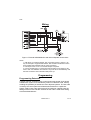
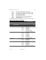
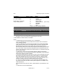
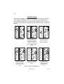
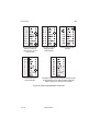
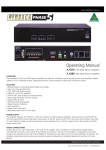
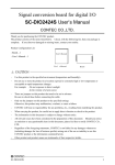
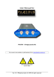
4600
Installation and User Guide
Compatible Equipment
4601
4602
4603
4604
4605
4608
4609
7150
Long range and short range pendant transmitters
Hand held PA
Programmable transmitter
Contact transmitter
Short range dual channel transmitter
PIR
Smoke detector
Viper radio vibration detector (supplied by Weyrad Electronics).
496368 Issue 1
1 of 12
4600
Introduction
The 4600 electronic intruder alarm system is a fully programmable, 8-zone,
bells only, radio security system, designed for domestic installations and to
comply with BS 6799, Class 3.
The system comprises a main control panel, which is hard-wired to an
external bell/strobe, together with detector/transmitters, which are wire-free
and communicate with the main control panel by means of radio signals.
Technical Specification
Electrical
Input supply voltage
Short-circuit protection
= 225-253VAC, 50Hz, Max 30VA.
= Outputs short-circuit protected for indefinite
periods by means of Polyswitches which will
recover after removal of short-circuit.
Reverse polarity protection = Battery connections are reverse polarity
protected for at least 5 minutes.
Battery back-up
= Back-up time, panel only with fully charged
battery, typically 20 hours 12V Lead Acid
battery, typically 2.1AH. Float charge voltage
13.7V typically. Charge time for flat battery,
maximum 14 hours, typically 6 hours.
Auxiliary output
= 13.7VDC. Continuous current available
200mA. Maximum short term current 1A for
up to 20 minutes.
Dimensions
= h x w x d 160 x 257 x 72 mm.
Weight
= 1.2 kg.
Humidity
= 80° RH.
Operating temp.
= -10° to + 55° C
2 of 12
496368 Issue 1
4600
Wiring
Figure 1. External SAB Bell/Strobe and Internal Speaker Connections
Notes:
1. SAB shown for negative applied. The connections shown in Figure 1 are
only an example of a typical SAB module. See the bell manufacture’s instructions supplied with individual units for more information.
2. Link tamper return to 0V if no external tamper is required.
3. Connect all bell wiring to control panel with exception of the trigger to the
siren or bell. The bell/siren will continue to ring from the on-board battery until
the final connections are made after initial power-up.
Programming
Programming Detectors
A series of six DIL switches on the control panel main printed-circuit board
enables each system to be identified by means of a different code, thereby
avoiding the possibility of interference from adjacent systems. The site code
is used by the control panel and all detector/transmitters in a particular
system. Select a site code and set the six DIL switches. Carefully note the
settings of the six site code DIL switches as this code is used when setting
each transmitter/detector.
496368 Issue 1
3 of 12
Initial Power Up
4600
Figure 2. Setting the Site Code
Consult the sections for individual 4600 series transmitters for details
on setting the DIL switches in each transmitter.
Initial Power-Up
Note: If an SAB bell is fitted to the system and completely wired, then the bell will
ring until power is applied to the panel and bell lid closed.
1. Apply power.
2. Enter the user code 1234 to silence the internal sounder.
The panel is now in DAY mode. The walk test and other LEDs may be
illuminated but please ignore them at this stage.
To Enter Programming Mode
Make sure the Day LED is glowing before trying to enter programming mode.
1. Press 0 then Enter.
2. Key in the engineer access code (default 7890).
3. Open control panel cover to activate the lid tamper switch.
All panel LEDs start to flash. You may now proceed to program the
various system options with the panel open.
4. Fit programming stencil on control panel.
4 of 12
496368 Issue 1
4600
Programming Commands
Programming Commands
To change the factory default program use the commands listed in this
section as follows:
1.
Key in the command number followed by Enter.
One of the LEDs on the display glows. The programming stencil shown
in Figure 3 (Part number 495521, Issue 1) shows the LEDs used by
each command.
Figure 3. Programming Stencil
2.
Key in the appropriate value for the command followed by Enter. See
“Engineer Program Commands” for the values taken by each command.
The panel gives three short high-pitched beeps if it accepts the values
you enter.
If you enter an incorrect value the panel gives a longer, lower-pitched
fault tone.
When you complete a command correctly, the panel flashes all LEDs to
show that it is ready for another command.
Note: It is not necessary to program all the options. Where a change has to be made
to a particular option, proceed directly to the appropriate section. Refer to
factory default programming.
Defaults
When delivered from the factory the panel has the following defaults:
Engineering access code 7890.
User access code is 1234.
496368 Issue 1
5 of 12
Engineering Program Commands
4600
Zone 1
Entry/Exit zone/part set/auto restore (PIR)
Zone 2
Part set/entry route zone/auto restore (PIR, VIPER)
Zone 3
Part set/entry route zone/auto restore (PIR, VIPER)
Zone 4
Auto restore (PIR, VIPER)
Zone 5
Auto restore (PIR, VIPER)
Zone 6
Nothing selected (i.e., full set only door contact)
Zone 7
PA/auto restore (Pendant or hand-held PA)
Zone 8
Fire/auto restore
All other defaults are shown in the Engineer Program Command list by a ‘y’.
Engineering Program Commands
To change:
Engineer Access Code
Consecutive Code Jamming
Instant Night Mode
Remote Set
First Zone Lockout
Part Set Exit Timer
Key in: Then:
20 ENTER nnnn ENTER
32 ENTER Any* ENTER
33 ENTER Any* ENTER
34 ENTER Any* ENTER
35 ENTER Any* ENTER
41 ENTER 1 ENTER
2 ENTER
3 ENTER
4 ENTER
5 ENTER
6 ENTER
Bell Duration Timer
42 ENTER 1 ENTER
2 ENTER
3 ENTER
4 ENTER
5 ENTER
6 ENTER
7 ENTER
8 ENTER
43 ENTER 1 ENTER
2 ENTER
3 ENTER
4 ENTER
44 ENTER 1 ENTER
2 ENTER
3 ENTER
4 ENTER
5 ENTER
6 ENTER
Entry Timer
Full Set Exit Timer
6 of 12
496368 Issue 1
Notes
Default
See note 1
7890
See note 2
ON
See note 3
OFF
Zone 8 LED shows status
ON
See note 4
ON
= 10 seconds
= 20 seconds
y
= 40 seconds
= 60 seconds
= Continuous
= Instant (1.5s bleep
followed by 20s silent)
= 1.5 mins
= 3 minutes
= 5 minutes
y
= 10 minutes
= 15 minutes
= 20 minutes
= Continuous
= 10s (for testing only)
= 10 seconds (see note 5)
= 20 seconds
y
= 40 seconds
= 60 seconds
= 10 seconds
= 20 seconds
y
= 40 seconds
= 60 seconds
= Continuous
= Final door or 60 seconds
4600
To change:
Zone Options
(n = zone number)
Press Clear to clear zone
of any existing options.
Carrier Jamming Detect†
Bell Test
Strobe Test
Panel sounder test
Load defaults
Leave Programming
Engineering Program Commands
Key in: Then:
Notes
Default
5n ENTER 1
= Double knock
2
= Chime
3
= Auto Restore
4
= Entry Route
5
= Personal Attack
(see note 6)
6
= Entry/Exit
7
= Part Set
8
= Fire
Press ENTER after making selections.
65 ENTER Any* ENTER Zone 8 LED shows status
ON
91 ENTER Bell sounds for 10seconds (see note 7)
92 ENTER Strobe active for 60seconds (see note 7)
93 ENTER Panel sounder active for 10secs (see note 7)
98 ENTER
99 ENTER
*Any = press any numbered key to toggle the option on or off. Zone 8 LED indicates
the status of the current selection (LED glowing function ON).
† Not available on earlier versions of software.
Notes:
1. While entering the new password, zone 1 LED flashes.
2. Zone 2 LED glows and zone 8 LED shows the status of the Consecutive
Code Checking function.
3. Zone 3 LED glows and zone 8 shows the status of the Instant Night Mode
(LED glowing-Function ON). Instant Night Mode only affects entry/exit zones
that are also part-set zones. If the mode is ON, part-set entry/exit zones
become instant alarm zones, rather than entry/exit zones during part-set mode
only. If the mode is OFF, the part-set entry/exit zones are entry/exit zones as
normal. This mode has no affect in the full-set mode or on entry/exit zones that
are not part-set zones.
4. Unless Entry Route zones are included, DO NOT select the First Zone
Lockout function, as an entry fault would make it impossible to unset the panel
without first creating an alarm condition.
5. The 4600 system features a two-ply entry time. After the selected entry time
has expired, the system will enter into an internal alarm for a period equal to
50% of the selected entry time. If the panel is not unset by entering a valid
code by the time the 50% extra time has expired, the system will enter into a
full alarm condition (internal sounders/external bell and strobe).
6. If you do not select an option for a zone it becomes a Normal Night zone.
The system will not let you select certain options together, for example: entry
route and PA zone.
You must select Auto restore for PIRs, smoke detectors, Viper detectors, and
PAs.
7. Press Enter to end test prematurely.
496368 Issue 1
7 of 12
Leaving Programming Mode
4600
Leaving Programming Mode
When all programming is complete:
1. Remove the programming stencil and close the panel.
2. Key in 99 then Enter.
The panel returns to Day mode.
If faults are present on entering the Day mode, the panel gives a low-high
bleep. Investigate any faults before proceeding. If the control panel does not
go into the Day mode, either the control panel lid or bell cover is open.
Restoring Factory Defaults
1.
Enter programming mode.
All LEDs flash.
2. Key in 98 then Enter.
The panel loads all the factory defaults.
Note: Using this command will erase all values, including user and engineer codes,
which have been previously programmed. If you have lost the engineer or user
code, you may load the factory default programme by removing all power and
holding down OMIT and 1 while restoring power.
Testing
Walk Test
The system flashes the Walk Test LED after a preset number of operations
to advise you to carry out a walk test.
1. Key in 3 then Enter.
2. Enter the user code (default 1234).
The Test LED glows steadily.
3. Open or activate each zone in turn.
The appropriate zone LED glows as you activate the zone. The panel
gives a loud tone while the zone is open or activated. When you close
the zone the display shows the next open or activated zone, or continues to display the last open or activated zone if there are no other zones
open.
Note: In normal use the 4608 uses a 2.5 minute lockout time in order to extend
battery life. The lockout timer works as follows:
a) The unit detects movement, signals the panel, and starts the lockout timer.
b) If the unit detects movement while the lockout timer is running, then it
restarts the lockout timer but does not signal the panel.
c) When the lockout timer expires the unit signals the panel the next time it
detects movement.
If you want to test the unit in normal use you should wait at least three minutes
between activations.
On older units, enter user code (default 1234) and then key in 3. The test
LED glows steadily. Carry on from step 3.
8 of 12
496368 Issue 1
4600
Fault Finding
Under normal operating conditions, the Fault and Alarm LEDs are dark (the
power LED glows while mains is on). The Walk Test LED flashes after a
preset number of operations to advise that a walk test should be carried out.
Any other LEDs glowing or flashing signify either a fault or alarm condition, as
follows:
Low battery on zone
detector. Replace battery.
Jamming present on zone 4.
Check for interfering radio
signals. Activate detector/
transmitter and enter user
code twice. If fault persists
then call Scantronic product
support.
Zone activated during exit
time or during re-arm
period after an alarm.
Enter user code twice.
Tamper on zone active
during exit time or during
re-arm period after an
alarm. Enter user code
twice.
Radio frequency blocked.
Call Scantronic technical
support.
Consecutive code
jamming detected. Illegal
attempts made to
establish system site
code.
Figure 4. Fault Finding Displays
496368 Issue 1
9 of 12
Fault Finding
4600
Remote setting transmitter
jammed on. Check for
obvious causes, e.g. test
switch turned on.
If the mains fails then the
power LED flashes.
Low battery on remote
setting transmitter.
Replace battery.
Zone indicated has been
activated.
If the battery voltage is low then the power LED goes dark and
the panel beeps every 30s. When the battery voltage falls
below 8V (approx) then the panel stops operating.
Figure 5. Fault Finding Displays Continued
10 of 12
496368 Issue 1
4600
User Commands
From the Keypad
Full Set
User code + 2
Unset
User code
Part Set
User code + 1
Omit Zones
User code + 2 + OMIT + zone number. (Repeat
OMIT + zone number for all zones to be omitted.)
Keypad PA
1+3
Silence Bells
User code
Reset
User code
Change User Code
6 + Enter + existing code + new code + Enter
Walk Test
3 + Enter + User code + activate detectors + Enter
to end test
On older units: User code + 3 + Enter + activate
detectors + Enter to end test
Chime On/Off
4 + Enter + User code
From the 4605UK-55 Remote Setting Device
Full Set
Press top button
Unset
Press top button
PA
Press the two orange side buttons together
496368 Issue 1
11 of 12
12 of 12
496368 Issue 1