1
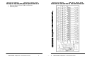
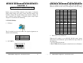
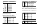
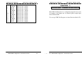
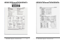
Operations Manual
USB Photo Relay Card
Operations Manual
The S2 switch is used to identify USB card ID. Please set
different card ID to each card (do not duplicate card ID setting).
CHAPTER 2
HARDWARE CONFIGURATION
1
ON
OFF
ON
OFF
ON
OFF
ON
OFF
ON
OFF
ON
OFF
ON
OFF
ON
OFF
Before you use the USB 8 channels relay output / 8 channels
photo couple input card, please ensure that the jumpers and
switches setting. The proper jumper and switches settings for
the 8 channels relay output / 8 channels photo couple input
adapter are described in the following.
2.1 Switch Settings
1. S1 Reset
The S1 switch is used to reset 8051, the signal assignments are
shown in the following.
Pin
3,4
1,2
Signals
Reset SW+
Reset SW-
2
ON
ON
OFF
OFF
ON
ON
OFF
OFF
ON
ON
OFF
OFF
ON
ON
OFF
OFF
3
ON
ON
ON
ON
OFF
OFF
OFF
OFF
ON
ON
ON
ON
OFF
OFF
OFF
OFF
4
ON
ON
ON
ON
ON
ON
ON
ON
OFF
OFF
OFF
OFF
OFF
OFF
OFF
OFF
Card ID
-14
13
12
11
10
9
8
7
6
5
4
3
2
1
0
3. Down load revised firmware
When the S2 switch is set to ON ON ON ON status, means
down load revised firmware. please follow the steps shown in
the following:
1. Set S2 to ON ON ON ON.
2. Run USBBootloader program to down load revised firmware.
2. S2 USB ID
DECISION Computer International
USB Photo Relay Card
5
- 5 - 6
DECISION Computer International