1
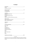
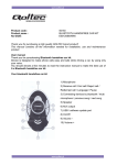
User Manual
CONTENTS
-1-
CONTENTS ................................................................................................................... 1
Chapter 1 Introduction .................................................................................................. 3
Overview of Hardware Elements ......................................................................................................... 4
Connection with PC .............................................................................................................................. 5
How to connect................................................................................................................................... 5
How to remove ................................................................................................................................... 5
LED Indicators................................................................................................................................... 6
Chapter 2 Setup Procedure............................................................................................ 7
Mobi™ Software Installation ............................................................................................................... 8
Installation for Windows XP ............................................................................................................. 8
Connection Establishment ................................................................................................................. 12
Connection Establishment for Windows XP .................................................................................. 13
Chapter 3 Utility Software .......................................................................................... 18
Using Utility Software........................................................................................................................ 19
Using Utility Software for Windows .............................................................................................. 19
Chapter 4 Uninstalling Mobi™ Software .................................................................... 25
Uninstalling Mobi™ Software............................................................................................................ 26
Uninstallation for Windows XP/2000............................................................................................. 26
-2-
Chapter 1 Introduction
This chapter describes that which should be confirmed
before using Mobi™ Access Card.
7
-3-
Overview of Hardware Elements
Main Unit
Antenna
~
~
Please adjust direction and angle according to the state
of signal strength.
Don’t use too much force to adjust antenna direction or
angle. It could damage the antenna.
Status LED
POW/ALM LED
It indicates state of iBurst. (P.6)
It indicates state of iBurst. (P.6)
PC Card Connector
-4-
Connection with PC
In order to use Mobi™ Access Card, your computer must satisfy the following requirements:
~PC Card Slot-TypeⅡcompliant with PC Card Standard 95 or later.
~PC-AT Compatible PC running WindowsXP/2000/Me/98Se or Mac OS X(MacOSX v10.1.5 or later).
How to connect
If this is the first time that Mobi™ Access Card is to be used on your computer, it is necessary to
install the device driver first. (Refer to “Mobi™ Software installation” on page 9).
The following describes the procedure how to connect Mobi™ Access Card with your computer.
1 Turn on the power to the computer.
2 Insert Mobi™ Access Card into the computer ’s PC Card Slot and make sure it is fully fitted in
the slot.
3 Double click the icon of PC Card on the computer’s task tray, and you should see the device
name [iBurst Modem] in the hardware device list of the appearing PC Card dialog window.
How to remove
1 Double click the icon of PC Card on the computer ’s task tray, and click the [Stop] button in the
appearing PC Card dialog window. Make sure that you select [iBurst Modem] in the PC Card
dialog window before click the [Stop] button.
2 A popup dialog window with the message [Safe To Remove Hardware] should appear. Click the
Ok button in the dialog window.
3 Remove Mobi™ Access Card from the computer’s PC Card Slot.
-5-
LED Indicators
Mobi™ Access Card has two LED indicators, Pow/ALM LED indicator and Status LED indicator.
The former indicates state of power to Mobi™ Access Card while the later indicates state of
communication or signal strength of received signal. The following table shows the relation
between the LED illumination patterns and Mobi™ Access Card states.
States
Power OFF
Power ON
Communicate with High
signal
Communicate with Low
signal
No communicate with High
signal
No communicate with Low
signal
No Rx Signal
Rx
Rx
LED #1 (POW/ALARM)
LED #2 (STATUS)
Blue
Red
Green
Amber
Yellow
All LEDs Off – No LEDs illuminated
On
Flashi
ng
Flashi
ng
Rx
ON
Rx
ON
ON
LED illumination patterns
On
: Continuous illumination
Flashing : Blink (0.1s on / 0.1s off)
-6-
Chapter 2 Setup Procedure
This chapter describes how to install Mobi™ software,
then guides you how to make a network connection so as
to use data communication service.
-7-
Mobi™ Software Installation
It is necessary to run Mobi™ software installation only when Mobi™ Access Card is to be used on
your personal computer the first time. Once it has be installed,there is no necessity for this
installation operation from the next connection.
Installation for Windows XP
1 Turn on the power to the computer.
2 Insert the provided Software Utility CD into your CD-ROM drive.
Don’t insert Mobi™ Access Card into your PC card slot when installation is running.
3 Mobi™ Setup starts, click the [Next] button.
4 Select [I accept the terms the license agreement], click the [Next] button.
-8-
5 Click the [Next] button after appearing dialog window as shown below.
6 Click the [Next] button.
7 The following dialog window will appear, and installation of software begins.
-9-
8 Click the [Continue Anyway] button in the appearing dialog window as shown below.
9 When the installing process finishes, the dialog window shown below will appear. Select “Yes,I
want to restart my computer now” and Click the [Finish] button in the dialog window.
10 After the restart, insert Mobi™ Access Card into your PC card slot.
- 10 -
11 If the operating system is able to recognize the inserted Mobi™ Access Card as a new installed
hardware, [Found New Hardware Wizard] will begin and the dialog window as shown below
will appear. Select [Install the software automatically(Recommended)] and click the [Next]
button in the dialog window.
12 The dialog window shown below will appear,click the [Continue Anyway] button.
- 11 -
13 The driver is installed on your PC.
14 After installation of the driver,the dialog window shown below will appear,click the [Finish]
button.
Connection Establishment
- 12 -
Connection Establishment for Windows XP
As Windows XP operating system supports PPPoE protocol, we don’t use connection application for
Mobi™ to configure network conection.
1 Click the [Start] button, followed by selecting [Control Panel] as shown below.
2 Click [Network and Internet Connections] in the [Control Panel] display.
3 Next, click [Set up or Change your Internet connection].
4 When the [Internet Properties] dialog window appears, click the [Setup] button.
- 13 -
5 [New Connection Wizard] will begin and the dialog window as shown below will appear.
Click the [Next>] button in the dialog window.
6 Select [Connect to the Internet] and click the [Next>] button.
7 Select [Set up my connection manually] and click the [Next>] button.
- 14 -
8 Select [Connect using a broadband connection that requires a user name and password] and
click the [Next>] button.
9 Fill in [ISP Name] edit box with an ISP Name, followed by clicking the [Next>] button. Note
that any ISP name is acceptable.
10
Enter user name and password and make sure that the [Make this the default Internet
- 15 -
connection] check box is checked. Click the [Next>] button.
11 Click the [Finish] button.
12
When the [Network and Internet Connection] window pane appears again, click [Set up
change your Internet Connection].
13 When the [Internet Properties] dialog window appears and the [Connections] pane is displayed,
- 16 -
confirm the connection name and make sure that the [Always dial my default connection] radio
button is checked, followed by clicking the [Apply] button. Then, click the [OK] button to close
the dialog window.
14
At this point, the connection configuration is complete. When you call Internet Explorer
program, [Dial-up Connection Wizard] will begin and the [Dial-up Connection] dialog window
as shown below will appear. Click the [Connect] button to connect to the network.
15 When the connection establishment process is complete, a message indicating the completion
of the connection completion will at the task tray as shown below.
- 17 -
Chapter 3 Utility Software
This chapters describe the features and usage of the
utility software for Mobi™ Access Card.
- 18 -
Using Utility Software
Using Utility Software for Windows
How to display utility dialog window
1 To open the utility dialog window, click the icon
on the computer’s task tray. When the
window opens, the [Link Info] pane will be displayed as shown below.
2 To close the utility dialog window, click the [OK] button or the [Cancel] button or the X mark at
upper-left corner of the dialog window.
- 19 -
Link Info Pane
Link Info pane can be displayed in the main dialog window bv clicking the [Link Info] tab.
Generally, the elements in the Link Info pane give information about the communication link
between Mobi™ Access Card and the access point to the network.
(1)
(2)
(4)
(3)
(5)
(6)
(7)
(8)
The following describes each item of the Link Info pane.
(1) UTID
UTID is used as the identifier of Mobi™ User Terminal.
(2) Link Status
Link Status indicates connection state of the communication link between Mobi™ Access Card
and the access point.
Connected
: The link is connected.
No Connected : Mobi™ Access Card is inserted in the PC Card slot but the link is not
connected.
NoCard
: There is no Mobi™ Access Card inserted in the PC Card Slot.
(3) Link Speed
Link Speed indicates speed of the link in both down and up direction.
- 20 -
(4) Frame Error Rate
Frame Error Rate indicates the FER of the received data.
(5) Signal Strength
Signal Strength indicates the signal strength of the received signal. Here, two kinds of indicators,
percentage indicator and 5-step indicator, are used to indicate the received signal strength.
The percentage indicator is the RSSI value in percent. On the other hand, the 5-step indicator
shows performance of the received signal in words as follows.
No Signal
: RSSI = 0%
Poor
: RSSI is in the range of 1~24%
Fair
: RSSI is in the range of 25~49%
Good
: RSSI is in the range of 50~74%
Excellent
: RSSI is in the range of 75~100%
(6) Current Data Rate
Current Data Rate indicates the current transmission throughput and the reception throughput.
(7) Total Byte Received
Total Byte Received indicates the total number of bytes of the data which Mobi™ Access Card
has received from the access point since the communication link is established.
(8) Total Byte Sent
Total Byte Sent indicates the total number of bytes of the data which Mobi™ Access Card has
transmitted to the access point since the ommunication link is established.
- 21 -
Setup Pane
Setup pane can be displayed in the main dialog window by clicking the [Setup] tab. Setup pane is
used to configure the display items in the Link Info pane.
(2)
(1)
(4)
(3)
(6)
(5)
The following describes usage of each item of the above figure.
(1) Check the [ON] radio buttons at the right hand side of the items you want to display in the
Link Info pane.
(2) Check the [OFF] radio buttons at the right hand side of the items you don’t want to display in
the Link Info pane.
(3) The configuration shown in the Display Setup subpane is activated by checking the [Apply]
button.
(4) The configuration in the Setup pane can be set to default (Default is the state in which all
radio buttons on the right hand side of display items are set to “ON”.) by clicking the [Reset]
button.
(5) By clicking the [Ok] button, the current configuration will be activated and the dialog window
will be closed.
(6) By clicking the [Cancel] button, the dialog window will be closed but the current configuration
won’t be activated.
- 22 -
About Pane
About pane is used to display the version numbers of utility, software and hardware and show
copyright notice.
(1)
(2)
(3)
The following describes the function of each item of the About pane.
(1) This shows the version number and the release date of the Utility Software.
(2) This shows the firmware version and the build date of Mobi™ Access Card in use.
(3) This shows the hardware version and the buld date of Mobi™ Access Card in use.
- 23 -
Icon Display in Tasktray
When the utility software for Mobi™ Access Card is active, an icon of the utility software will be
displayed in the task tray of the computer monitor according to communication activities on Mobi
™ Access Card.
The following shows the relation between the icons to be displayed in computer ’s task tray and
activities on Mobi™ Access Card.
Icon
Activities on Mobi™ Access Card
Mobi™ Access Card is not inserted in the PC Card slot.
There is no action of transmission or reception on Mobi™ Access Card.
Mobi™ Access Card is transmitting data.
Mobi™ Access Card is receiving data.
Mobi™ Access Card is both transmitting and receiving data.
From the task tray icon, user may also get information of Link Status, Total Byte Received, Total
Byte Sent, Signal Strength, which is displayed in the Link Status pane of the utility dialog window,
without opening the dialog window. This can be done by placing the mouse’s pointer over the
currently displayed icon of the utility software. The below figure shows an image of what happens
when the mouse pointer is placed on the task tray icon.
- 24 -
Chapter 4 Uninstalling Mobi™ Software
This chapter describes how to uninstall Mobi™ software.
- 25 -
Uninstalling Mobi™ Software
Uninstallation for Windows XP/2000
1 Close all programs that are currently running.
2 Remove the Mobi™ Access Card from the computer.
3 Click the [Start] button, followed by selecting [Control Panel] as shown below.
Click [Add or Remove Programs].
4 Select [iBurst] software, and click the [Change/Remove] button.
- 26 -
5 Click the [OK] button after appearing dialog window as shown below.
6 The following dialog window will appear, and uninstallation of software begins.
7 Click the [Finish] button after appearing dialog window as shown below.
- 27 -
- 28 -