1
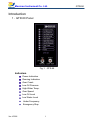
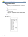
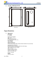
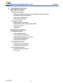
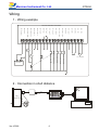
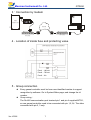
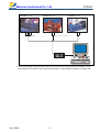
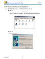
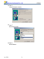
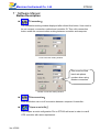
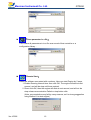
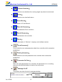
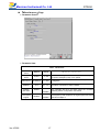
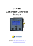
GTR-50
Generator Controller
Manual
Web Site:http://www.monicon.com.tw E - m a i l :s a l e s @ m o n i c o n . c o m . t w
Monicon Instrument Co. Ltd.
Introduction
1、GTR-50 Panel
Fig.1 GTR-50
Indicators
Power Indication
Running Indication
Over Crank
Low Oil Pressure
High Water Temp.
Over Speed
Low Oil Level
Low Water Level
Under Frequency
Emergency Stop
Ver.:V5005
1
GTR-50
Monicon Instrument Co. Ltd.
GTR-50
Operational Switch Function
ATS
Shorted ATS1 and ATS2 terminal behind the controller, the engine starts
automatically.
Manual
User starts the engine directly.
Off
Shutdown the engine or forbid start function.
Reset
1. Turn on the LCD backlit.
2. First time “Reset” shutdown the alarm. Second time “Reset” clears fault lights.
3. Holding down for a longer period will produce 1st and 2nd time “Reset” functions.
Light Test
Test lights for solid, clear, brightness and alarm.
2、Wirer Terminal
GTR-50 wirer terminal
Ver.:V5005
2
Monicon Instrument Co. Ltd.
GTR-50
GTR-50 Terminal
Number
Description
Code
Europium style Connector
1
Input power (Battery +)
B+
2
Ground (Battery -)
B-
3
Output starter relay
Motor
4
Output fuel valve relay
Valve
5
Output, Aux 3 relay
Out. 3
6
Output, Aux 2 relay
Out. 2
7
Output alarm relay
Alarm
8
Electrical trip relay
Trip 1
9
Electrical trip relay
Trip 2
10
Input, Aux 2 switch
In. 2
11
Input, Aux 0 switch
In. 0
12
Input, Aux 3 switch
In. 3
13
Input, Low oil press. switch
L.O.P.
14
Input, High water temp. switch
H.W.T.
15
Ground (Battery -)
B-
16
Input, Aux 1 switch
In. 1
17
Start 1
A.T.S. 1
18
Start 2
A.T.S. 2
19
Input, Frequency detect terminal
F.D. 1
20
Input, Frequency detect terminal
F.D. 2
OK: Solid “green” LED display
Polarity fault
RS-485
1
2
3
4
Communication Port
1. B +
2. A
3. B
4. B -
[1]:Output Relay function can be changed according users requirements。
[2]:Output trip Relay is intended to be used to trip the Breaker or AVR filed current in
order to cut off load to the generator。
Ver.:V5005
3
Monicon Instrument Co. Ltd.
GTR-50
3、CASE DIMENSIONS
71mm
4mm
64mm
136 mm
144mm
3mm
Back View
Side View
Specifications
1、General
DC Supply:
8 ~ 36 VDC
Power Consumption:
Max. 10 W
Measuring Frequency:
0 ~ 80 Hz (Min AC Volt: 10 V)
Relay Output:
10 A / 30 VDC
Software Platforms:
Windows 98, Windows ME, Windows 2000, Windows XP (recommend)
Communication Protocol:
RS-485 (Dynamic encryption by Monicon technology)
Operating Temperature Range:
-30 ℃ ~ +70 ℃
Dimension (W x H x D):
72 mm x 144 mm x 74 mm
Panel Cut-out (W x H):
67 mm x 138 mm
Weight:
0.63 Kg (1.39 lb.)
Ver.:V5005
4
4mm
Monicon Instrument Co. Ltd.
2、Controller Function
General Function:
Network function:
Remote start/stop and pester the controller by network circuitry
Parameter setting and reading
Input and output monitor
Fault history readout
Panel function:
Manual start / stop engine.
Automatically start / stop engine by ATS.
Reset the Genset.
Light test.
Protection function:
Engine respect:
Over crank protection
Low oil pressure protection
High water temperature protection
Low water level protection
Over speed protection
Generator respect:
High frequency protection
Low frequency protection
Peripheral respect:
Lower fuel level protection
Aux. Input
Ver.:V5005
5
GTR-50
G20. F.D.2
G19. F.D.1
G18. AT S 2
G17. AT S 1
G16. Input 1
G15. G ND.
Water Temp. S W.
Oil P ressure S W.
Fuel Level SW.
GTR
G14. H .W.T Input
G13. L.O .P. Input
Eme rgency S top
MTR-1
傳送器
Controller
G12. Input 3
RS-232
6P4C
10~3 00 ACV
Water Leve l SW.
Ala rm
BATTERY
G11. Input 0
G10. Input 2
G09. Tr ip 2
G08. Tr ip 1
G07. Alarm
G06. O utput 2
G05. O utput 3
G04. F uel Valve
G03. S tar ter Motor
6
Ver.:V5005
-
+
G02. G ND
G01. B attery +
2、Connection in short distance
~
ATS
Fu el
Val ve
GTR-50
Monicon Instrument Co. Ltd.
Wiring
1、Wiring example
GTR-50 Generator Controller
S tar ter
Mo tor
Monicon Instrument Co. Ltd.
GTR-50
3、Connection by modem
GTR
Controller
MTR -2
PSTN
Modem
Modem
4、Location of inside fuse and protecting value
Fuse1:100 mA
Fuse2:750 mA
Fuse3:6 A
5、Group connection
Every genset controller must be have own identified number to support
recognition by software. Go to System/Other page, and change the id
number.
Group wiring:
The Rs-485 communication port terminal pin 1 and pin 4 supplied MTR-1,
so one genset controller need to be connected with pin 1,2,3,4. The other
connected with pin 2, 3 only.
Ver.:V5005
7
Monicon Instrument Co. Ltd.
Address:41
1 2 3 4
GTR-50
Address:42
Address:43
2 3
2 3
(RS-485)
Only connect Pin 2, 3
MTR-1
*It is strong suggestion using another power source to power the communication card (MTR-1), If the
wire length over 25 meters. That can prevent the MTR-1 in unpredictable condition by voltage drop.
Ver.:V5005
8
Monicon Instrument Co. Ltd.
GTR-50
GTR Series Software Installation
6、GTR-50 Software Installation Procedure
Step 1:
Insert the installation disc in the CD ROM drive, and then choose the folder
“GTR50”, double-click “Setup.exe”. The wizard will guide you to finish whole
setups.
Step 2:
Welcome Screen
Ver.:V5005
9
Monicon Instrument Co. Ltd.
Step 3:
Choose Destination Location
Step 4:
Select Program Folder
Step 5:
Restart Windows
Ver.:V5005
10
GTR-50
Monicon Instrument Co. Ltd.
GTR-50
7、Software Manual
Button Description
『Connection』
The connection-setting window displayed after clicked this button. User need to
be set comport, connection method and controller ID. Then click connection
button make the communication working between controller and computer.
Local connection setting window
User need be filled
baud rate phone
number when using
Modem connection
Modem connection setting window
『Disconnection』
Push this button can cut off connection between computer & controller。
『Open an exist file』
This is open an exist configuration File to GTR-80 soft ware in order to comfit
GTR controller with same requirement。
Ver.:V5005
11
Monicon Instrument Co. Ltd.
GTR-50
『Save parameter in a file』
This is save all parameters in to a file as a record of that controller or a
configuration library。
『Remote Start』
When the software connected with condoner, User can start Engine by 2 ways.
1 Enable Running Interval timer then click OK. The engine will start at next
second, and will be stop until timer expired.
2 Direct click OK, then the engine will start at next second, and will not be
stop unless communication Failed or stop button click.
(Note: communication may fail by many reasons, so it is strong suggestion
using Method 1 to start engine)
Ver.:V5005
12
Monicon Instrument Co. Ltd.
GTR-50
『Remote Shutdown』
Click this button can shutdown the running engine by network remote start.
『Reset』
Click this button can clear fault status。
『Fault Record』
Read Rawest 16 Fault Record。
『Read All Parameter』
Reads all parameters From controller。
『Set All Parameter』
Write all parameters into controller 。
『About』
Display Information of “Monicon” company, and software version.
『Read Parameter』
Click this button can read parameters back from controller while connection
established.
『Setting Parameter』
Click this button can write parameters into controller while connection
established.
『Parameter Re-Flash』
After user write parameters in to controller, the parameter is in un-working
memory until click this blotter to Load in the run procure。
『Massage Clear』
This button can clear the text in massage window。
Message
Ver.:V5005
13
Monicon Instrument Co. Ltd.
GTR-50
Parameter Screen Description
1、『System』Page
『Crank』page
Parameter Screen
Parameter Item
Crank Parameter
Ver.:V5005
Parameter
name
Default
Range
Cranking time
10 Sec
3~20
Set the maximum limitation of the cranking time.
Crank interval
10 Sec
3~30
Interval between Cranking.
Crank
disconnect
beyond
frequency
20 Hz
15~30
When frequency goes about this setting, the starter motor
will escape.
Crank enable
minimum
frequency
20 Hz
15~30
When frequency is below this setting, the starter motor
can be activated.
Cranking
Attempt
3 Attempt
1~10
Total cranking attempts.。
D e s c r i p t i o n
14
Monicon Instrument Co. Ltd.
GTR-50
『Engine』Page
Parameter Screen
Parameter Item
Engine Parameter
Ver.:V5005
Parameter
name
Default
Range
Pre-Add Fuel
Time
0 Sec.
0~10
The time of pre-add Fuel before start Engine
Engine halt
period
2 Sec.
1~30
Engine will be halt a period of time after fault shat down
Shutdown
After Trip
30 Sec.
30~900
When trip activated the Run light will flash and trip relay
energized, the control will shut down the engine if fault
not clear before setting time up
Coiling time
1 Sec.
1~240
After normal shat down the engine the cooling procedure
will be activated cooling time will be no used in fault shut
down or by manual switch off
Energies to
stop
10 Sec.
1~20
The timer is setting how long the fuel solenoid should be
energized to stop the engine completely
Pre-Heat
Timer
0 Sec.
0~60
The Pre-Heat procedure will activated AUX. Output if
selected before engine start.
Detect
Alternate
frequency
Enable
Enable/
Disable
Escape starter by frequency.
Detect
Lubricant
pressures sw
Disable
Enable/
Disable
Escape starter by lubricant pressure built up.
D e s c r i p t i o n
15
Monicon Instrument Co. Ltd.
GTR-50
『Run Hour』Page
Parameter Screen
Parameter Item
Run Hour Parameter
Ver.:V5005
Parameter
name
Range
Default
Second
0~59
0
Set Run Hour “Second” Value.
Minute
0~59
0
Set Run Hour “Minute” Value.
Hour
0~99
0
Set Run Hour “Hour” Value.
100 Hour
0~99
0
Set Run Hour “100 Hour” Value.
D e s c r i p t i o n
16
Monicon Instrument Co. Ltd.
GTR-50
『Miscellaneous』Page
Parameter Screen
Parameter Item
Misc. Parameter
Ver.:V5005
Parameter
name
Default
Range
Safety On
Timer
10 Sec.
3~20
All alarms are ignored until safety on timer expired,
except the emergency stop, over speed.
De-bounce
50 Attempt
5~200
De bounce time can avoid the Interference by Electronic
or magnetic.
Controller
Address
41 H
01~FF
Controller address is for identification while multiple
controllers connected in same network.
System
Non-Auto
Enable
Low speed
Engine
Disable
D e s c r i p t i o n
Enable/
Disable
Enable/
Disable
17
The controller will lunch an alarm when the controller
operating switch in off position if checked.
The frequency vale multiple 2 as engine speed if checked
otherwise multiple 3.
Monicon Instrument Co. Ltd.
GTR-50
2、『Input』Page
『Sensor Switch』Page
Parameter Screen
Parameter Item
High Water Temp. Switch Parameter
Parameter
name
Default
Range
Enable
Checked
Enable/
Disable
Action Mode
Shutdown
Shutdown
Switch Type
N.O.
Delay Time
1 Sec.
D e s c r i p t i o n
Checked means enable.
N.O.:This switch returns
pressure conditions, once
switch will open.
N.O./ N.C.
N.C.:This switch returns
pressure conditions, once
switch will close.
a closed signal during low oil
oil pressure is established the
an open signal during low oil
oil pressure is established the
0.25~50 Delay Time
Low Oil Pressure Switch Parameter
Ver.:V5005
Parameter
name
Default
Range
Enable
Checked
Enable/
Disable
Action Mode
Shutdown
Shutdown
Switch Type
N.O.
Delay Time
1.5 Sec.
D e s c r i p t i o n
Checked means enable.
N.O.:This switch returns
pressure conditions, once
switch will open.
N.O./ N.C.
N.C.:This switch returns
pressure conditions, once
switch will close.
0.2~40
Delay Time
18
a closed signal during low oil
oil pressure is established the
an open signal during low oil
oil pressure is established the
Monicon Instrument Co. Ltd.
GTR-50
『Aux. Input』Page
Parameter Screen
Parameter Item
Aux. Input Parameter
Parameter name
Enable
Name as
Action Mode
Switch Type
Timer
Aux. Input 0
Checked
Emergency
Stop
Shutdown
N.C.
0.2 Sec
Aux. Input 1
Checked
Battle
Indicate
N.O.
1 Sec
Aux. Input 2
Checked
Low Water
Level
Shutdown
N.O.
5 Sec
Aux. Input 3
Checked
Low Fuel Level
Trip
N.O.
10 Sec
Descriptions:
The Aux. Inputs can be named as Emergency Stop, Battle, Lower, Low Water Level, Low Fuel
Level, Low Battery Volt, High Fuel Level, Pre-Alarm、charge fail、Over Load, Low Water
Temp., Pre-Heat and Spare.
Ver.:V5005
19
Monicon Instrument Co. Ltd.
GTR-50
『Operation Switch』Page
Parameter Item
Parameter Item
ATS Switch
Parameter
name
Default
Range
Enable
Checked
Enable/
Disable
Hold Time
1 Sec.
D e s c r i p t i o n
Checked means enable.
0.25~2.5 Minimum holding time.
Manual Switch
Parameter
name
Default
Range
Enable
Checked
Enable/
Disable
Checked means enable.
Hold Time
1 Sec.
0.25~5
Minimum holding time.
D e s c r i p t i o n
Reset Switch
Ver.:V5005
Parameter
name
Default
Enable
Enable/
Disable
Hold Time
0.25~2.5
Range
D e s c r i p t i o n
Checked Checked means enable.
0. 25 Sec. Minimum holding time.
20
Monicon Instrument Co. Ltd.
GTR-50
『Frequency』Page
Parameter Screen
Parameter Item
Over Frequency Parameter
Parameter
name
Default
Range
Enable
Checked
Enable/
Disable
Action Mode
Shutdown
Shutdown
66 Hz
60~72
Frequency
Setting
(60 Hz)
Frequency
Setting
(50 Hz)
Delay Time
D e s c r i p t i o n
Checked means enable.
This Range will be difference according to system
frequency.
55 Hz
50~60
2 Sec.
1~10
Delay Time.
Under Frequency Parameter
Parameter
name
Default
Range
Enable
Checked
Enable/
Disable
Action Mode
Indicate
Frequency
Setting
(60 Hz)
Frequency
Setting
(50 Hz)
Delay Time
Ver.:V5005
54 Hz
D e s c r i p t i o n
Checked means enable.
Four kind action modes can be selected. Shutdown,
Trip, Alarm, Indicate.
48~59
This range will be limited according to system
frequency.
45 Hz
40~50
6 Sec.
1~10
21
Delay Time
Monicon Instrument Co. Ltd.
GTR-50
Minimum Detect Frequency
Parameter
name
Default
Range
Enable
Enable/
Disable
Checked
Checked means enable.
Frequency
Setting
30 Hz
10~45
Under this setting all frequency protection will be
disabled
D e s c r i p t i o n
System Frequency
Parameter
name
Default
Range
Frequency
Setting
60 Hz
50、60
D e s c r i p t i o n
System frequency value
3、『Output Relay』Page
Parameter Screen
Parameter Item
Auxiliary output Relay Faction
Parameter
name
Output Relay 0
Output Relay 1
Output Relay 2
Output Relay 3
Ver.:V5005
Default
Range
D e s c r i p t i o n
(1) “Error Occur”, (2) “Standby”, (3) “Pre-heat”, (4)
See
“Start Period”, (5) “Start Interval”, (6) “Run”, (7) “Stop”,
Error occure
Description (8) “Engine Halt”, (9) “Generator Working”, (10) “Reset
Activate”, (11) “System Trip”, (12) “System Alarm”, (13)
“Fire Charger”, (14) “Reserve 1”, (15) “Reserve 2”, (16)
“Reserve 3”, (17) “Under Frequency Active”, (18)
Pre-heat
See
duration
Description “Reserve 4”, (19) “Reserve 5”, (20) “Reserve 6”, (21)
“Reserve 7”, (22) “Reserve 8”, (23) “Reserve 9”, (24)
“Spare”, (25) “Engine Running”, (26) “Low Water Level
Active”, (27) “Reserve 10”, (28) “Low Fuel Level
Energized to
See
stop
Description Active”, (29) “Over Crank”, (30) “High Coolant Temp.
Active”, (31) “Over Speed Active”, (32) “Low Lube.
Press. Active”, (33) “Emergency Stop Active”, (34)
“Reserve 11”, (35) “Reserve 12”, (36) “Auto Start”, (37)
See
Fire changer
Description “Reserve 13”, (38) “Reserve 14”, (39) “Reserve 15”
22