1
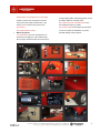
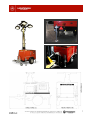
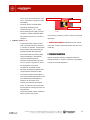
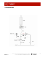
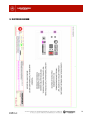
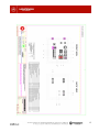
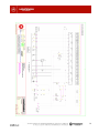
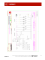
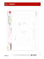
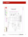
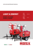
OPERATING AND MAINTENANCE MANUAL LIGHTING TOWER APOLO COMPACT INDEX 1. Introduction .............................................................................. 2 2. Safety rules ............................................................................... 2 3. General description .................................................................. 4 3.1 Composition of the lighting tower .................................... 4 3.2 Technical information ........................................................ 6 4. Putting into service .................................................................. 8 5. Operations to perform once its use is completed ................ 10 6. Maintenance............................................................................. 11 7. Troubleshooting ...................................................................... 12 8. Hydraulic diagram ................................................................... 13 9. Electrical diagram ................................................................... 14 10. Warning commissioning ........................................................ 23 11. Guarantee certificate ............................................................. 23 1. INTRODUCTION 2. SAFETY RULES It is our goal in this manual to provide you with basic Before working with the machine, carefully read the safety information and instructions for proper installation and use rules given and become informed regarding local safety of your lighting tower. requirements. It is essential that you carefully read all the safety rules Installation, operation, maintenance and repair are to be and warnings before, during and after you put your lighting carried out only by authorized, competent personnel. tower into operation, as only in this way can we ensure you will have optimal normal service under ideal conditions for reliability and safety. The owner is responsible for maintaining the lighting tower in a safe condition. Parts and accessories should be replaced when they are not in proper working order. HIMOINSA S.L. considers itself obligated to warn you that As a preface to the contents of this manual, we will next the information in this manual can be considered valid only detail the basic criteria that you should meet with special on its date of issue, since technological advances and attention to your own safety and that of others: updates of current regulations, may oblige us to make changes without prior notice. This manual and the remaining reference documentation General safety precautions stop the equipment quickly in the event of an are part of the lighting tower you have acquired and emergency and fully understand the operation of should be kept and protected from anything that might all the lighting tower controls. damage them during the life of the tower. This documentation should accompany the equipment when it Before operation, it is necessary to know how to Perform the relevant checks of the genset and the tower before putting them into operation, in is transferred to another user or owner. order to avoid possible accidents affecting personnel or the equipment itself. The manual should always be kept close by, so that it can be consulted when needed. Although the information Never allow other persons to use the lighting given in this manual has been checked in detail, tower without previously having given them the HIMOINSA can accept no responsibility for any writing, instructions required for its proper and safe use. typing or transcription errors. supervision of an adult familiar with the use of the In accordance with Directive CEE 85/4374 and its lighting tower. subsequent modification 99/34, HIMOINSA is free of any responsibility resulting from defective installation, improper Do not allow minors to use it without the Prevent access to the tower operation area by use of the machine, and noncompliance with the rules children and domestic animals in order to protect contained in this manual. them, to the extent possible, from being injured by any part of the equipment. 2 Stop and disconnect the genset immediately The connection of these to the land-dispersion should any abnormal situation arise during must be made with bare copper wires conductors operation. Locate and correct the problem before with a minimum section of 16mm2, or if not starting it back up again. available, galvanized iron with a 50 mm2 section. Make sure that the lighting tower is properly The resistance of such conductor, including the located on a completely level firm surface to contact resistance, must not exceed 0.15 Ohm. ensure that it operates properly and remains Fire safety completely stable in unexpected winds. Do not fill the generator set fuel tank while it is running or when the engine is hot. Do not tow the lighting tower on the highway at speeds exceeding 90 km/h. Always refill the generator set fuel tank in a ventilated area with the engine completely off. Lower the mast when wind speed exceeds 80 km/h. Do not fill the fuel tank to more than 90% of its capacity. Check that the tank cap is completely IMPORTANT: To make the lighting tower safe and completely stable, always position the jack legs with the closed. bubble or spirit level. Check to make sure that no fuel has spilled onto the set. Should this occur, it must be cleaned off and dried well before starting up the equipment. Safety against danger of electrocution Never handle the lighting tower, and the Residual fuel could cause a fire. generator set that is part of it, when you have wet explosive. It is forbidden to smoke, have any hands or feet. flame present or cause sparks during fuelling or Never touch bare or disconnected wires. normal equipment operation. Maintain all electrical wires and connections in Always use appropriate plugs for the outlet Do not place objects near air intakes, breathers, receptacles on the generator set, never use zinc or the engine exhaust, because doing so could or wires without a plug or with bare ends. The cause overheating of the genset and use of these wires directly in the plugs can create consequently a fire hazard. a high risk of electrocution. Keep flammable materials and objects away when operating or refueling. good condition. Gasoline is inflammable and its vapors are Do not place any object on the lamp bulbs Whenever wires are observed to be in poor immediately after they have been in use because condition, replace them and make sure they are they reach very high temperatures. installed correctly before restarting the lighting tower. Metal parts of installations which are exposed to Safety from burns Never touch the engine or the genset exhaust human contact, and due to an insulation flaw or pipe when it is running or for several minutes other reasons, may get in contact with voltage, after it stops, as this can cause serious burns. must be connected to land-dispersion device. Before handling and maintaining it, allow the The lighting tower and the panel have been engine to cool. equipped with their respective grounding terminals. Never touch the halogen bulbs for 10 minutes after use, as they can cause serious burns. 3 3. GENERAL DESCRIPTION and the operating buttons; the mast is operated 3.1. Composition of the lighting tower controlled safely. The upper button controls HIMOINSA lighting towers are built by our technical and production team using the highest quality materials, sparing no expenses to achieve high performance, operationally versatile lighting towers. by two buttons that allow the mast to be vertical raising of the mast up to 9 m in 13 seconds and the lower button controls lowering of the mast to its final locked position in 25 seconds. Raising and lowering of the mast is powered solely by 12 volt DC coming from the battery so They include a tower kit and a generator set, put together as a compact and balanced piece of mobile equipment. that this operation is independent of auxiliary power input. 5. 2 Auxiliary power outlets. The tower has two The Tower Elevation Kit consists of: 16 amp auxiliary outlets, to provide power to auxiliary equipment. 1. A hydraulic, telescopic vertical elevation mast with 9 sections, which reaches a total working height of 9 meters and has a light beam that can be manually oriented through 360 by manual rotation. Raising time: 13 seconds. Retraction time to the locked position: 25 seconds. 2. Supporting bracket for 4 IP65 flood lights, each with a 1,000 watt 90,000 lumen metal halide bulb. Bulbs rated to operate at ambient temperatures from -20 to 45C. 6. 1 Auxiliary power input connection (male receptacle, 2L + N, 230V, 23A) that enables supplying current to the lamps (and/or the auxiliary receptacles) from an external source (mains, i.e. a power grid or another generator set). The tower can operate if we power it externally, even with the engine off. 7. Double safety lock on the mast. This locks the mast locking and prevents unwanted rotation during transport. To be able to rotate the mast and orient the light beam it has to be unlocked. 8. Handle for locking-unlocking the mast in the operating position. This handle enables locking Noteworthy in the rest of the tower assembly: 3. Sound proofed generator set powered by the reliable, water cooled and fuel efficient YANMAR model 3TNV76 diesel engine . 4. A water-tight control, protection and management panel. The control and protection panel incorporates the M6 controller, an hour meter, siren, fuel level gauge, voltmeter, ammeter and thermal-magnetic circuit breakers for protecting lamps and auxiliary outlets down the mast orientation when in use. 9. Fluid retention tray (retention of 120% of the fluids of the engine and tank). 10. External fuel tank filler. Fuel tank cap with safety lock. 11. Emergency stop. 12. Ample accesses for maintenance and inspection. 13. 4 Leveling legs, two of them extendible to ensure perfect tower stability on any working surface. Eliminates the risk of tipping over under adverse environmental conditions. 14. Bubble or spirit leveler, located on the upper part of the genset to ensure precise tower leveling. 4 15. Automatic on/off programmer for the lamps, for signal lights (brake and flashing lights) as well located on the back of the generator set with as marker reflectors and hand brake. easy access and simple programming. Light 18. Includes eye hook and forklift slots on the sensor on the outside on the genset cover rear enabling transport by forklift. (OPTIONAL). 19. Tie down rings for fastening during transport 16. Engine exhaust system. to ensure complete immobilization to prevent Mobile equipment: possible damage during transport. 17. Transport kit: The tower is designed to be relocated on the highway, and includes jockey wheel, tongue with ball coupler and connections 5 3.2. Technical information 6 7 4. PUTTING INTO SERVICE Before putting the lighting tower into service, make sure that it is properly located on completely level ground to ensure proper operation and secure it against unexpected winds. Note: Do not raise the mast at wind speeds exceeding F.1 F.2 F.3 F.4 80 km/h 4.1. Checking equipment fluid levels Check the various equipment fluid levels: For the genset oil and gasoline level and air filter (See generator set manual). For the hydraulic fluid level (See 6. Maintenance) 4.2. Anchoring 4.3. Lamp Orientation Once these simple, essential checks have been The lamps come already installed in the tower and we performed, which ensure optimal tower and generator set can orient them simply using small levers that allow operation, we next anchor the APOLO COMPACT lighting them to be easily moved over 180. F. 5 tower properly. To do this, the following steps need to be followed precisely: Remove the lock pins, pull out the legs and align the holes, then reinsert the lock pins. F. 1 Turn the handle on top the telescoping leg jack until resistance is felt, in this way the tower F.5 can be levelled and secured on the ground in the 4.4. Connection between genset and lighting work area designated. F. 2 -3 tower Only the front legs can be screwed out as the back ones are fixed and are adjustable only with their pins. F. 4 Once the leveling legs are adjusted and the lighting tower is correctly leveled using the bubble or spirit level, the jockey wheel is lowered The tower is built as a compact tower directly connected to the set. It is not necessary to make any kind of special connection. 4.5 Operating the lighting tower mast so it is supported on the ground in the work area. IMPORTANT: In order to raise the mast, it is essential F. 5 to have already set the hand brake. For safety reasons, if the hand brake is not set, the mast will not raise. F. 6 8 Operating the tower is very simple, by using the raising MPORTANT NOTE: For safety reasons, whenever the and lowering buttons located on the genset control panel brake is released, the mast will automatically descend. and following these simple instructions: 1. Make sure the mast is in the locked position. F. 7 2. Raise the mast by pressing the lift button located on the control panel. F. 8 – 9 F.6 F.10 F.11 F.12 F.13 F.7 4.6. Starting up the generator set VERY IMPORTANT: Do not start the genset under a load, that is, make sure that the thermal-magnetic circuit F.8 F.9 breakers are off. F. 14 Turn the starter key, located on the side panel on the generator set, following the start up procedure given in the The mast has a lock which locks in lamp orientation. To generator set instructions. F. 15 change the orientation, the lock must be released by bringing the lever to the RELEASE position, turning the mast to the desired position and then locking it down with the lever by bringing it to the LOCK position. F. 10 – 11 OK In order to return the mast to the original position, the lever must be put in the RELEASE position and then it will be F.14 F.15 possible to rotate the mast to the original position. Once this is done, lock it down with the mast lock. F. 12 For safety reasons, once a job is completed, it is recommended that the mast stay in the original, locked position that it comes in from the factory to prevent damage to the machine. F. 13 4.7. Turning on the lamps Finally, in order to turn on the lamps, the Apolo Compact lighting tower includes 3 different modes for turning on the lamps using the automatic on/off programmer installed on the inside F. 16, which are: 9 a) By means of the light sensor (Selector Position I) 5.2. Folding the mast We recommend that you wait 10-15 minutes before b) Manually (Selector Position 0) c) With the programmable timer (Selector Position II) performing this operation, due to the high temperatures reached by the flood light filaments, since it makes them quite vulnerable to small vibrations that are unavoidably NOTE: To use the programmable timer, see the programmable timer user’s manual. It is only necessary to turn on the switches located on the generated when taking down the mast. 5.2.1 Lowering the telescopic mast By pressing the lowering button installed on the genset control panel. F. 20 generator set panel. F. 17 F.20 F.16 F.17 5.3 Retracting the telescoping jack legs IMPORTANT: Before retracting the jack legs it’s necessary to first make sure to lower and set the jockey VERY IMPORTANT: In order to perform any wheel firmly on the ground. F. 21 – 22 raising/lowering or orientation operation, the lamps always must be turned off. 5. OPERATIONS TO PERFORM ONCE ITS USE IS COMPLETED F.21 5.1. Disconnecting the flood lights a) Selector in Position 0: Manual Mode Flip off the flood light switches and stop the generator set. F. 18 – 19 F.18 F.19 F.22 Once this operation is finished, retract the telescoping jack legs and put the legs in the transport position, that is, with the fastening supports up. F. 23 – 24 F.23 F.24 b) Selector in Position I: Using the light sensor c) Selector in Position II: Using the programmable timer 10 5.4. Relocation on the highway. 6. Maintenance In the event that it is desired to relocate the tower on the highway, the jockey wheel will need to be retracted. GENERATOR SET: General maintenance (See generator set manual) NOTE: When raising the wheel, always make sure that it LIGHTING TOWER: It suffices to say that the fits in properly, to keep it from spinning during transport and damaging the machine. F. 25 – 26 tower itself does not require extensive maintenance, since the simplicity of the system and the quality of the materials used to build it ensure that. However, we should know about the following operations: ¡Ojo! In the event of burnt out halogen bulbs, it is advisable to use gloves or a protective cloth as a substitute. F.25 F.26 Do not touch the bulbs directly with your fingers. If we are operating the lighting tower in a moist, dusty place, we need to clean and dry it Place the ball coupler in position on the vehicle and when we see a green area appear on the safety button we can frequently. be sure it is locked in properly F. 27 To change or check the battery, the access is on the right side of the lighting tower. F. 28 F.27 F.28 Steel cables and pulley assemblies: o Periodically inspect the condition of IMPORTANT: If the green area on the button is not visible, cables every 100 hours or once a it is not connected securely. month. o When the nominal diameter of the steel cable has decreased 10% from corrosion or abrasion, it should be replaced immediately. o Inspect the wire stands and, in the event that one has broken, replace the steel cable as soon as possible. 11 o If there is any kind of deformation: kink, Tornillo de Electro-válvula Tapón llenado Aceite knot or crushed spot, replace the cable immediately. o Important: Always use steel cables specified by the lighting tower Tapón Vaciado Aceite manufacturer (the 6 37 + 1 type) o F.29 When operating under highly corrosive conditions, coat the galvanized cables with oil every 300 hours or 3 months of If you have any questions, however, contact our technical operation. department. Hydraulic system: F. 29 o Inspect the hydraulic system and the MOBILE EQUIPMENT: Maintenance (See manual level of hydraulic fluid every 300 hours on the hitch coupler, inertia brake system and axle of the or 3 months of operation. Add hydraulic mobile kit) fluid if needed, always eliminating any hydraulic fluid leak that might exist. o In the event that the hydraulic cylinder raises with difficulty or intermittently, check the hydraulic fluid level. o Change the hydraulic fluid every 2400 hours or 2 years of operation or when it 7. TROUBLESHOOTING Given the systems’ simplicity, equipment failures are virtually nonexistent. However, if there are any problems, contact our technical department. has degraded or if it becomes contaminated by another product. o Whenever changing the hydraulic fluid, change the filter and clean the tank. o In the event of solenoid valve failure or some other problem that keeps the mast from descending automatically, this operation can be carried out by loosening the solenoid valve bypass screw. To raise the mast it is important that the solenoid valve bypass screw be fully tightened. o Inspect the hydraulic system if hydraulic fluid is noticed on the ground. 12 8. HYDRAULIC DIAGRAM 13 9. ELECTRICAL DIAGRAM 14 15 16 17 18 19 20 21 22 WARNING 23 24 HIMOINSA HEADQUARTERS: Ctra. Murcia - San Javier, Km. 23,6 | 30730 SAN JAVIER (Murcia) Spain Tel. +34 968 19 11 28 - +34 902 19 11 28 | Fax +34 968 19 12 17 Export Fax +34 968 33 43 03 Manufacture facilities: SPAIN - FRANCE - INDIA - CHINA - USA Subsidiaries: ITALY | PORTUGAL | POLAND | GERMANY | SINGAPORE | UAE | MEXICO | PANAMÁ | ARGENTINA M-AC_10-2011_en