1
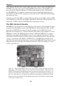
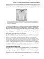
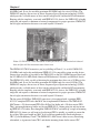
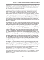
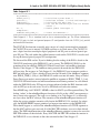
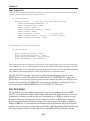
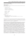
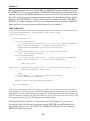
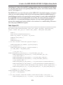
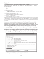
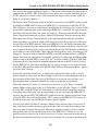
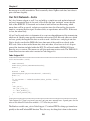
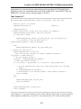
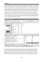
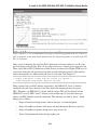
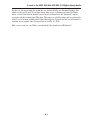
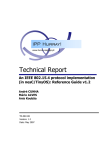
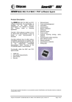
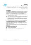
Hands-On Zigbee
By Fred Eady
March 2007 ▪ ISBN 978-0-12-370887-8 ▪ Paperback ▪ 352 Pages ▪ $59.95
Features:
o The ONLY one-stop Zigbee resource available- from
basics to sniffers to specs
o 7 easy-to-assemble ZigBee projects allow the reader to
follow along...hands-on!
o Working hardware and software examples included in
every chapter
Since its recent introduction, the ZigBee protocol has created an
enormous amount of buzz in venues from magazine covers to
trade show floors to water coolers. Its promise of providing a
simpler, cheaper, more power-efficient WPAN (Wireless
Personal Area Network) alternative to WiFi and Bluetooth has
opened up new data collection possibilities in application areas
from industrial controls to medical devices to intruder alarms. Yet, despite this widespread interest, there
is still little information available that goes beyond detailing the spec itself. Missing from the current
ZigBee lexicon is practical, application-oriented guidance from an expert, specifically geared to aid
engineers in implementing this new technology. Enter respected designer and popular columnist Fred
Eady! With his new book, he provides the only comprehensive how-to ZigBee guide available.
Order from Newnes.
Mail: Elsevier Science, Order Fulfillment, 11830 Westline Industrial Dr., St. Louis, MO 63146
Phone: US/Canada 800-545-2522, 1-314-453-7010 (Intl.) ▪ Fax: 800-535-9935, 1-314-453-7095 (Intl.)
Email: [email protected] ▪ Visit Newnes on the Web: www.newnespress.com
Table of Contents
Chapter 1: Speaking the Language
Chapter 2; You Are Dangerous and You’re Going to Hell
Chapter 3; Keep Running
Chapter 4: A Loot At the ZMD 900 MHz IEEE 802.15.4/ZigBee-Ready
Radio
Chapter 5: Atmel Does IEEE 802.15.4 and ZigBee Too
Chapter 6: They Do Everything BIG in Texas
Chapter 7: Maxstream/Xbee
Chapter 8: Hopping Down the Bunny Trail
Chapter 9: Cirronet Adds Southern Flavor to IEEE 802.15.4 and ZigBee
Chapter 10: Silicon Laboratories
Chapter 11: Renesas
Chapter 12: Freescale
Chapter 13: Panasonic
Chapter 14: DLP Design
Chapter 15: Microchip
Chapter 16: Telegesis
Chapter 17: Cypress MicroSystems’s CapSense
CHAPTER
4
A Look at the ZMD 900-MHz
IEEE 802.15.4/ZigBee-Ready Radio
I sincerely hope you were wearing shoes while we were running through PHY and MAC hell.
Your feet may be hot but you can now utilize the power of your mind to distance yourself
from pain, as you are on the road to mastery of IEEE 802.15.4. Whether you like it or not,
you are now a student of IEEE 802.15.4. There won’t be any heavy IEEE 802.15.4 meditation sessions and I won’t require you to strike a mid-air IEEE 802.15.4 Kung Fu pose while
effortlessly defying gravity. While we’re on Kung Fu movie stunts, the best one I ever saw
had Kung Fu masters that could spin themselves into the ground and then cover themselves
with dirt. These guys would spin into their holes along a path and as the bad guys approached
they would spin themselves out of the ground and fight. Naturally, the spinning, hole-digging
masters also had the ability to hang in the air forever while kicking the living crap out of their
opponents. Once the fight was over, the masters would spin themselves back into hiding and
await their next victims.
IEEE 802.15.4 Done the ZMD Way
The more you learn about how IEEE 802.15.4 works, the easier it will be to work with ZigBee. This book is all about doing IEEE 802.15.4 and ZigBee things. Right now, let’s do some
real IEEE 802.15.4 stuff. ZMD offers a really good IEEE 802.15.4 development kit that puts
all of the elements of IEEE 802.15.4 together using ZMD44102 900-MHz IEEE 802.15.4
radio technology and basic ZMD44102 radio firmware. You’ve already been exposed to the
ZMD44102 900-MHz transceivers, since I used them to check Beacon intervals in Chapter 3.
The ZMD44102 transceiver can operate in the 868-MHz band, which is the domain of European IEEE 802.15.4-compliant transceivers, and in the 915-MHz ISM in North America,
Australia and New Zealand. I don’t know about you, but I’m a cordless-phone freak. I like
to keep up with the latest cordless-phone technology and I always send my Mom a new
phone when I get one. Remember when cordless phones reached into the 900-MHz frequency band? Those new 900-MHz babies could talk farther and longer on a single battery
charge than the existing 46/49-MHz cordless units. Plus, it was a little bit harder to eavesdrop on the 900-MHz phones, as a standard police scanner could tune you in to all of the
neighborhood 46/49-MHz phones. Not too long after the 900-MHz phones became popular,
2.4-GHz phones showed up on the WalMart shelves. My take is that consumers saw the
higher-frequency phones as technologically better since the frequency number was higher,
and the marketing guys and gals knew that. It’s kinda like buying a computer these days—the
43
Chapter 4
faster the better. My foray into cordless phones does have a point to make. The ZMD44102
900-MHz transceivers only compete with 900-MHz cordless phones and 900-MHz proprietary radio traffic. With the addition of 2.4-GHz cordless phones to the 2.4-GHz band, a
2.4-GHz IEEE 802.15.4-compliant transceiver now has to contend with Bluetooth traffic,
802.11b/802.11g WLAN traffic, proprietary radio traffic in the 2.4-GHz band and the ubiquitous microwave oven.
To further prove that 900 MHz is a viable frequency band for serious ZigBee work, the ZMD
folks sniffed the air at the June 2006 ZigBee Open House. The results indicated that there was
much more 2.4-GHz traffic than 900-MHz traffic competing for airspace.
The ZMD Starter Kit Bundle
The IEEE 802.15.4 concepts that will be offered up in this chapter will be brought to fruition
using the Starter Kit Bundle version of the ZMD Wireless Sensor Starter Kit. That “bundle”
means that our ZMD Wireless Sensor Starter Kit includes an extra ZMD44102 Starter
Board that can be employed as a Daintree Networks SNA Sniffer capture module or an extra
IEEE 802.15.4 node. The ZMD44102 Starter Board’s ZMD44102 IEEE 802.15.4-compliant/ZigBee-ready single-chip 900-MHz transceiver serves under the command of a Silicon
Laboratories C8051F120 microcontroller with an associated JTAG interface. Since the word
“sensor” is synonymous with ZigBee and IEEE 802.15.4, the ZMD folks included one of
their TSic 106 precision temperature sensors on each of the ZMD44102 Starter Boards. If you
look just below and to the right of the Silicon Laboratories C8051F120 in Photo 4.1, you’ll
see the 3-wire TSic 106.
Photo 4.1: Silicon Laboratories C8051F120. The 10-pin header interfaces the Silicon
Laboratories USB Debug Adapter to the ZMD44102 Starter Board’s C8051F120. The
ZMD44102 and all of its supporting electronics are directly to the right of the C8051F120.
Power for the ZMD44102 Starter Board is supplied by the USB connection or the power
jack. The switch bank to the right of the power jack configures the ZMD44102 Starter
Board into either the 868-MHz or 900-MHz band and defines the ZMD44102 Starter Board
as a central or remote node.
44
A Look at the ZMD 900-MHz IEEE 802.15.4/ZigBee-Ready Radio
The Silicon Laboratories portion of the ZMD Wireless Sensor Starter Kit Bundle includes the
C8051F120 microcontrollers, Silicon Laboratories’ driver package for the Keil PK51 C compiler and a Silicon Laboratories USB Debug Adapter, which I’ve photographed in Photo 4.2.
Photo 4.2: Silicon Laboratories USB Debug Adapter. This little puppy provides a programming
and debugging path between the Keil PK51 C compiler/µVision3 environment and the
ZMD44102 Starter Board.
A 4K demo version of Keil’s PK51 C compiler is included with the Starter Kit Bundle. However, you’re going to need the full version of the Keil PK51 C compiler to fully utilize the
supporting C source code that comes with the ZMD Wireless Sensor Starter Kit. For those of
you that only want to evaluate the ZMD radio or the C8051F120 microcontroller, all of the C
source code examples are also provided as ready-to-program hex files that you can push down
into the C8051F120 using the USB Debug Adapter and Silicon Laboratories Flash programming utility that come with the ZMD Starter Kit Bundle.
The ZMD Starter Kit Bundle also comes with a 30-day trial version of Daintree Networks
SNA. The Daintree Networks SNA (Sensor Network Analyzer) package is a professional
IEEE 802.15.4 packet sniffer. Everything you need to know about a transmitted IEEE
802.15.4 packet is available via the Daintree Networks SNA application’s integral window
panes. Fortunately, the Daintree Networks SNA demo included with the ZMD Wireless Sensor Starter Kit is the professional version, which allows you not only to see the bits, but to
visualize a ZigBee-enabled IEEE 802.15.4 network as well. The ZMD44102 Starter Boards
are compatible with Daintree Networks SNA. So, we can and will use one of the ZMD44102
Starter Boards as the Daintree Networks SNA 900-MHz capture device.
The ZMD44102 Transceiver
The ZMD44102 CMOS transceiver you’re eyeballing in Photo 4.3 is an 868.3-MHz/ 902928-MHz band single-chip multichannel IEEE 802.15.4-compatible system-on-chip device.
License-free operation is provided by the ZMD44102 on the 868.3-MHz European band and
the 902-MHz-to-938-MHz North American ISM (Industrial, Scientific and Medical) bands.
The ZMD44102 is fully capable of obtaining the maximum burst data rate of 20 Kbps in the
45
Chapter 4
868-MHz band. It can also reach the maximum 900-MHz band data rate of 40 Kbps. The
ZMD44102 employs the services of Direct Sequence Spread Spectrum technology (DSSS),
which provides a reliable means of data transfer in high-traffic and hostile RF environments.
Keeping with the simplicity associated with IEEE 802.15.4 devices, the ZMD44102 is highly
integrated and requires a minimum of external components for proper operation. ZMD44102
line-of-sight transmission distances can reach beyond 100 meters.
Photo 4.3: ZMD44102 CMOS transceiver. It looks just like its 2.4-GHz cousins but it doesn’t
have to fight with the microwave oven for air time.
The ZMD44102 CMOS transceiver you’re eyeballing in Photo 4.3 is an 868.3-MHz/ 902928-MHz band single-chip multichannel IEEE 802.15.4-compatible system-on-chip device.
License-free operation is provided by the ZMD44102 on the 868.3-MHz European band and
the 902-MHz-to-938-MHz North American ISM (Industrial, Scientific and Medical) bands.
The ZMD44102 is fully capable of obtaining the maximum burst data rate of 20 Kbps in the
868-MHz band. It can also reach the maximum 900-MHz band data rate of 40 Kbps. The
ZMD44102 employs the services of Direct Sequence Spread Spectrum technology (DSSS),
which provides a reliable means of data transfer in high-traffic and hostile RF environments.
Keeping with the simplicity associated with IEEE 802.15.4 devices, the ZMD44102 is highly
integrated and requires a minimum of external components for proper operation. ZMD44102
line-of-sight transmission distances can reach beyond 100 meters.
The low-power 20/40-Kbps ZMD44102 transceiver is also equipped with a complete IEEE
802.15.4–compliant PHY and a thin MAC that is implemented in hardware. The ZMD44102
MAC houses a 128-byte transmit FIFO (First In First Out) buffer and a 256-byte receive FIFO.
That’s just enough temporary buffer area for one IEEE 802.15.4 frame going out and two incoming IEEE 802.15.4 frames. Even though the ZMD44102 MAC can buffer up a couple of incoming
IEEE 802.15.4 frames, we will want to clear the input FIFO as quickly as possible to prevent the
loss of data. What good would any MAC be if it could not automatically check and generate a
CRC (Cyclic Redundancy Check)? The ZMD44102’s MAC doesn’t have to worry about being
substandard, as it generates frame CRCs and checks incoming frames for the correct CRC.
46
A Look at the ZMD 900-MHz IEEE 802.15.4/ZigBee-Ready Radio
Remember slotted and unslotted networks? I told you there would be a test later. The
ZMD44102 can be used in standard unslotted CSMA-CA networks and in slotted CSMA-CA
networks. When used in slotted networks, the ZMD44102 has the capability to handle the
GTS area that may be associated with a superframe.
In addition to its ability to easily operate in slotted and unslotted network situations, the
ZMD44102 MAC operates in a multitude of other modes. The ZMD44102 MAC has to
receive as well as transmit. If the ZMD44102 MAC belongs to a PAN Coordinator, the
ZMD44102 MAC will be asked to perform active scans to determine RF energy levels (ED)
or find the most suitable channel on which to start a new PAN. If the ZMD44102 MAC finds
itself in the End-Device role, a passive scan may be requested in an attempt to find a Beacon
that would signal a PAN Coordinator is within range. It’s the MAC’s job to execute that scan.
Beacon generation and Beacon tracking are both tasks that are handled by the ZMD44102
MAC, depending on whether the device associated with the ZMD44102 MAC is a PAN Coordinator or an End Device.
Many of the MAC tasks such as scanning and superframe component handling are regulated
by time. Normally, peripheral interrupts and microcontroller timers would be put on the front
line to handle the timekeeping and task scheduling. Servicing interrupts and shepherding
internal timers gobble up microcontroller resources. To help keep the microcontroller focused
on the application instead of the ZMD44102 MAC’s timing requirements, the ZMD44102 incorporates a gaggle of its own internal timers. The ZMD44102 uses a pair of separate clocks
to pull off its timing tricks. The 24-MHz system clock is used to clock the digital core and
a separate 32.768-kHz clock, which supports sleep and power-down modes, and acts as an
RTC. Both of the ZMD44102’s internal clocks, in one manner or another, support the set of
IEEE 802.15.4-oriented timers that are integrated into the ZMD44102’s HW-MAC. The RTC
continues to run when the 24-MHz system clock is shut down during sleep and Global Power
Down modes. Shutting down the 24-MHz clock reduces the ZMD44102’s power consumption. Since the RTC runs full time, it can maintain network time. This allows the ZMD44102
in an End Device to sleep and always keep track of superframe time. Recall that in slotted
networks the best thing for an End Device to do is sleep and wake just before the superframe
that will service it begins.
Most IEEE 802.15.4/ZigBee transceivers use an SPI portal to communicate with a host microcontroller. By implementing an industry-standard SPI portal, the ZMD44102 allows the
IEEE 802.15.4 designer to pair the ZMD44102 up with just about any of today’s off-the-shelf
microcontrollers. There may be instances when the SPI hardware interface is not accessible.
No worries. The ZMD44102 is also capable of passing data and commands over a parallel
interface made up of the host microcontroller’s general-purpose I/O pins.
The ZMD Wireless Sensor Starter Kit documentation uses the IEEE 802.15.4 standard’s
nomenclature in their datasheet and user manual language. That’s a good thing. As you read
about the ZMD44102, you can directly relate its operation to the relevant sections of the
IEEE 802.15.4 standard.
47
Chapter 4
Preflighting the ZMD44102
I thoroughly enjoyed getting the ZMD Starter Kit Bundle up and running. The demo application code and Silicon Laboratories drivers that came with my ZMD Wireless Sensor
Starter Kit were designed to be used with Keil’s uVision2 environment. We will be using
the latest version of the Keil PK51 C compiler, which is built around uVision3. After some
investigation, or should I say, after things wouldn’t work quite right, I found that the Silicon
Laboratories USB Debug Adapter required the uVision3 drivers loaded in order to enable
the recognition of the USB Debug Adapter’s USB interface from within the Keil PK51 C
compiler’s debug utilities set-up windows. Once I got the Keil PK51 C compiler to recognize
the Silicon Laboratories USB Debug Adapter, I performed a test compile of the BCS (Basic Communication Software) source that came with the ZMD Wireless Sensor Starter Kit.
Everything came out lovely and I engaged the uVision3’s virtual DEBUG button to pour my
newly compiled BCS hex file into the ZMD44102 Starter Board’s C8051F120 Flash. The
idea behind the ZMD Starter Kit Bundle is to allow the development kit user to apply the
ZMD44102 hardware directly to the mechanisms of IEEE 802.15.4. The actual “application”
stuff can then be layered on top of the transport foundation the ZMD44102 Starter Boards
provide. A ZigBee or IEEE 802.15.4 application does not have to be complex. The simple act
of reading a temperature or monitoring a switch is considered an application in the ZigBee
and IEEE 802.15.4 worlds.
I want to continue to show you what is going out of the network node antennae. Since
the ZMD44102 is a 900-MHz radio, we must configure the Daintree Networks SNA
for 900-MHz band operation and prepare the associated Daintree Networks SNA IEEE
802.15.4-compliant frame-capture hardware. It’s only logical (and necessary) to use the third
ZMD44102 Starter Board as the frame-capture hardware for the Daintree Networks SNA. The
ZMD44102 Starter Board is compatible with the Daintree Networks SNA application. An application note on the Daintree web site provides in detail what is required to put a ZMD44102
to work as a Daintree Networks SNA capture device. In addition, a precompiled and readyto-load Daintree driver hex file is included with the ZMD Wireless Sensor Starter Kit Bundle.
All we have to do is load up the Silicon Laboratories standalone Flash programming utility,
which also was a component of the ZMD Wireless Sensor Starter Kit Bundle, and drop the
Daintree Networks SNA driver/capture code into the C8051F120 Flash on the newly tasked
ZMD44102-based IEEE 802.15.4 capture module.
Firing Up the ZMD44102
Before we jump off into turning on radios, there’s business that the microcontroller needs for
us to take care of first. The initialization of the ZMD44102 Starter Board is taken care of up
front in the main function of the BCS. In this case, the C8051F120 is the target microcontroller and the function calls in Code Snippet 4.1 invoke the instructions needed to get the
C8051F120 on course.
48
A Look at the ZMD 900-MHz IEEE 802.15.4/ZigBee-Ready Radio
Code Snippet 4.1
****************************************************************************
WD_DISABLE();
SYSCLK_Init(); /* initializes system clock */
portInit(); /* initializes crossbar, i/o lines and interrupts */
zmdInitHal(); /* initializes the ZMD’s HAL */
mlmeResetRequest(TRUE); /* init the PHY and MAC layer with its default values */
EA = 1; /* enable global interrupts */
zmdGpd(OFF);
zmdReset(HOLD_TIME_3); /* resets the ZMD44102 */
****************************************************************************
Code Snippet 4.1: This is standard stuff as far as microcontrollers go. The Silicon Laboratories
C8051F120 gets its clock and general-purpose I/O configuration from the SYSCLK_Init, portInit
and zmdInitHal functions.
The SYSCLK_Init function essentially only consists of a single instruction that commands
the C8051F120 to use its internal 24.5-MHz oscillator as its clock source. The C8051F120
uses a digital crossbar to multiplex digital peripherals and I/O ports to selected general-purpose I/O pins. The code within the portInit function works on the C8051F120’s crossbar and
sets up the desired general-purpose I/O configuration.
We discussed the HAL earlier. If you’re thinking that the coding of the HAL is based on the
C8051F120 interfacing to the ZMD44102, you’re correct. The ZMD44102 HAL lays the
groundwork for the zmdGpd (ZMD44102 Global Power Down) and zmdReset functions
listed in Code Snippet 4.1. The zmdReset timing controls the mode that the ZMD44102
will reset into. For instance, in Code Snippet 4.1, the ZMD44102 reset argument specifies a
RSN pin hold time of 730 ms, which will reset into the Off mode. If the zmdReset argument
were HOLD_TIME_1 (500 µs), the ZMD44102 would reset into idle mode. Sleep or Global
Power Down reset mode is entered when the zmdReset argument is HOLD_TIME_2 (3 ms).
C8051F120 SPI initialization and millisecond/microsecond timing routines are also defined
within the ZMD HAL code. SPI support is future enhanced within the HAL functions with
calls for SPI byte reads and writes as well as SPI block read and write routines.
Does MLME ring a bell? BONG!! MLME is short for MAC Layer Management Entity. The
leading “mlme” in the mlmeResetRequest function call tells us that a MAC management action is about to be requested. The code we are looking at in Code Snippet 4.1 is technically
one layer above the MAC sublayer. The semantics of the mlmeResetRequest function call
follow the service primitive semantics called out in the IEEE 802.15.4 standard. So, technically the MLME-RESET.request primitive has been put into motion via the MLME-SAP.
What should happen as a result of the mlmeResetRequest function call’s TRUE argument is
that the MAC sublayer gets reset and all of the MAC PIB attributes are reset to their default
values. The ZMD implementation of the mlmeResetRequest primitive issuance also resets the
PHY PIB attributes to their defaults. Every MAC PIB and PHY PIB attribute that matters to
the ZMD44102 is set to defaults in the code contained within Code Snippet 4.2.
49
Chapter 4
Code Snippet 4.2
****************************************************************************
void mlmeResetRequest(BOOL SetdefaultPIB)
{
if (SetdefaultPIB) {
phyPIBInit(TRUE); // init phy layer with default values
macPIB.macBeaconPayloadLength = 0;
macPIB.macBeaconOrder = 0x0F;
macPIB.macBSN = 0x00;
macPIB.macCoordShortAddress = 0xFFFF;
macPIB.macDSN = 0x00;
macPIB.macPANId = 0xFFFF; // not associated
macPIB.macShortAddress = 0xFFFF; // no short address
macPIB.macSuperframeOrder = 0x0F;
}
}
void phyPIBInit (BOOL defaultValue)
{
if (defaultValue)
{
phyPIB.phyCurrentChannel = 0x00;
phyPIB.phyChannelsSupported = 0x7FF;
phyPIB.phyTransmitPower = ZMD_TX_PWR_0;
phyPIB.phyCCAMode = CCA_THRESHOLD;
}
}
****************************************************************************
Code Snippet 4.2: This is a ZMD implementation of the MLME-RESET.request primitive. The ZMD
coders decided that it was a good idea to go ahead and initialize the PHY too. Note that the default
MAC Beacon Order and Superframe Order values define an unslotted network.
OK. The C8051F120 crossbar and general-purpose I/O are configured correctly and the
ZMD44102 has a viable SPI connection to the C8051F120. The ZMD44102 is sitting in a
default mode as we have only issued a power-on reset to the device and set its GPD pin to an
inactive state, preventing the ZMD44102 from entering a Global Power Down state. So far,
we have not spoken with the ZMD44102 via the C8051F120’s SPI portal.
Our First Steps
We are about to leave our crawling stage and put a step or two together with our first IEEE
802.15.4 data transmission. I didn’t mention the words network or ZigBee because we won’t be
establishing or joining a network and we won’t be utilizing any of ZigBee’s sublayer services
to send our little three-letter message. In fact, we don’t even have an End Device configured
to listen to us other than the Daintree Networks SNA capture device. Since there is no official
ZigBee or IEEE 802.15.4 network, the visualization feature of the Daintree Networks SNA won’t
be able to draw us up a pretty picture of the network. That’s OK. The Daintree Networks SNA will
still capture whatever bits we are able to throw out of the ZMD44102 Starter Board’s antenna.
50
A Look at the ZMD 900-MHz IEEE 802.15.4/ZigBee-Ready Radio
The code shown in Code Snippet 4.3 is what we will use to send the characters “ZMD” over
channel 1 of the 900-MHz ISM band.
Code Snippet 4.3
****************************************************************************
void UnslottedTx (void)
{
unsigned char ack;
unsigned char channel;
unsigned char tx_data[125];
unsigned char payload_length;
unsigned int destpanid, destaddr;
destpanid = 0xBEEF;
destaddr = 0xFEED;
channel = 0x01;
ack =0x01;
tx_data[0] = ‘Z’;
tx_data[1] = ‘M’;
tx_data[2] = ‘D’;
payload_length = 0x03;
plmeSetRequest(phyCurrentChannel, &channel);
zmdUnslottedTx(ack, tx_data, payload_length, destpanid, destaddr, AM_SHORT_ADDR);
}
}
****************************************************************************
Code Snippet 4.3: Do you recognize the plme prefix? PHY Layer Management Entity should have
rolled right off your tongue. It looks like a PHY management primitive is being used to request the
ZMD44102 to switch to and use channel 1. What do you think?
The functions and services provided by the ZMD BCS code package functions, such as the one
you see in Code Snippet 4.4, are responsible for making the little application in Code Snippet
4.3 so simple to conceive. In the IEEE 802.15.4 specification, the PHY is defined with integral data (PD-SAP) and management (PLME-SAP) SAPs (Service Access Points), which are
logical portals that pass primitives between the PHY and MAC sublayers. Since the PHY’s
PLME-SAP and PD-SAP are the only SAPs that join the MAC and PHY sublayers, the MAC
will always pass the final management or data primitive to the PHY sublayer and any data the
PHY needs to pass up the stack will always flow through the MAC. Recall that a primitive in
the true IEEE 802.15.4 sense does not within itself contain any executable elements or elements that will directly invoke program execution. A primitive simply carries what is needed to
assist in the action that the primitive is intended to initiate. In reality, primitives are simply data
structures that contain information that can be used and built upon by the neighbor sublayer
the primitive is passed to. Instead of passing the PLME-SET.request primitive in the traditional
IEEE 802.15.4 manner, the ZMD BCS code calls an executable function using the primitive
name. The “plme” portion of the plmeSetRequest function stands for PHY Layer Management
Entity. The PLME, as it is called in the IEEE 802.15.4 spec, is responsible for coordinating any
51
Chapter 4
management functions associated with the PHY. If a PLME-SET.request primitive were issued
in the IEEE 802.15.4 by-the-book method, a PLME-SET.confirm primitive would normally be
expected in response. The ZMD plmeSetRequest function returns the status directly to the function caller in lieu of passing a formal confirmation primitive. If you understand the idea behind
primitives, the ZMD IEEE 802.15.4-like functions should not ruffle your feathers. The ZMD
IEEE 802.15.4 shortcut methods work very well and the final results of executing a ZMD BCS
function instead of passing a primitive in the traditional way are identical.
Code Snippet 4.4
****************************************************************************
PHY_ENUM plmeSetRequest (PHY_PIB_ATTR PIBAttribute, void
*PIBAttributeValue)
{
switch (PIBAttribute)
{
case phyCurrentChannel:
if (*(UINT8*)PIBAttributeValue > 10) return PHY_INVALID_PARAMETER;
phyPIB.phyCurrentChannel = *(UINT8*)PIBAttributeValue;
zmdWriteReg(PHY_CHANNEL, phyPIB.phyCurrentChannel);
break;
case phyChannelsSupported:// this is a read only parameter
return PHY_INVALID_PARAMETER;
case phyTransmitPower:
if (*(UINT8*)PIBAttributeValue > 3) return PHY_INVALID_PARAMETER;
phyPIB.phyTransmitPower = *(UINT8*)PIBAttributeValue;
{
UINT8 temp_value;
temp_value = (zmdReadReg(TX_MODE) & 0xCF) | (phyPIB.phyTransmitPower << 4);
zmdWriteReg(TX_MODE, temp_value);
}
break;
case phyCCAMode: // this is a read only parameter
return PHY_INVALID_PARAMETER;
default: return PHY_UNSUPPORTED_ATTRIBUTE;
}
return PHY_SUCCESS;
}
****************************************************************************
Code Snippet 4.4: This ZMD version of a PLME-Set.request primitive services four PHY PIB attributes.
Note that the channels supported and CCA Mode PHY PIB attribute values cannot be altered in the
ZMD BCS package. However, the ZMD BCS code is so easy to follow, you can alter the BCS code
to change those read-only PHY PIB attributes to alterable variables.
The important thing to come away with from the code in Code Snippet 4.4 is that, once
the attribute value is placed into its position within the PHY PIB, the zmdWriteReg function launches the bits across the C8051F120-to-ZMD44102 SPI portal into the associated
ZMD44102 transceiver register.
52
A Look at the ZMD 900-MHz IEEE 802.15.4/ZigBee-Ready Radio
Code Snippet 4.5 takes all of the PAN, attribute and data values we specified in Code Snippet
4.3 and places them into the corresponding ZMD44102 registers. Let’s follow the flow of the
code in Code Snippet 4.5.
The ZMD44102 is reset into idle mode and the ZMD44102’s threshold trimming and register
values are set to their optimum values by the code contained within the zmdInit function. A
plmeGetRequest function call requesting the current channel is issued within zmdSetPibValues. If the PHY returns the channel number successfully, the current channel is loaded into
the ZMD44102. A second plmeGetRequest function call issued within zmdSetPibValues
retrieves the transmit power setting, which is also transferred via a zmdWriteReg SPI transaction to the proper ZMD44102 register.
Code Snippet 4.5
****************************************************************************
MAC_STATUS_ENUM zmdUnslottedTx (BOOL ack, UBYTE *payload, UINT8 payload_
length, UINT16 dest_pan_id, UINT16 dest_addr16, ADDR_MODE addr_mode)
{
UBYTE i;
UBYTE buffer[aMaxPHYPacketSize];
UBYTE irq_reason, rx_status, tx_status;
/*
zmdReset(HOLD_TIME_1); zmdInit(); zmdSetPibValues();
set the transmit frame MAC payload length */ zmdWriteReg(MSDU_TX_LENGTH, payload_length);
/* set sequence no */
zmdWriteReg(MHR_TX_SEQ_NO, macPIB.macDSN++); if (addr_mode == AM_SHORT_ADDR)
{
/* set pan id */
zmdWriteReg(MHR_TX_DST_PAN_ID_1, LOW_BYTE(dest_pan_id));
zmdWriteReg(MHR_TX_DST_PAN_ID_2, HIGH_BYTE(dest_pan_id));
/* set dest addr */
zmdWriteReg(MHR_TX_DST_ADDR16_1, LOW_BYTE(dest_addr16));
zmdWriteReg(MHR_TX_DST_ADDR16_2, HIGH_BYTE(dest_addr16));
/* set source addr */
zmdWriteReg(MHR_TX_SRC_ADDR16_1, LOW_BYTE(macPIB.macShortAddress));
zmdWriteReg(MHR_TX_SRC_ADDR16_2, HIGH_BYTE(macPIB.macShortAddress));
/* set the transmit frame MAC header frame control field, higher bits */
zmdWriteReg(MHR_TX_FC_2, FT_DST_ADDR_MODE_16 | FT_SRC_ADDR_MODE_16);
}
/* configure tx: use CSMA */
zmdWriteReg(MAC_TX_CONFIG, MC_CSMA); if (ack == ACK_REQUEST)
{
/* set the transmit frame MAC header frame control field, using Ack */
zmdWriteReg(MHR_TX_FC_1, FT_DATA | FT_ACK_REQUEST | FT_INTRA_PAN); 53
Chapter 4
/* store ACK and LQI, auto check sequence number enabled */
zmdWriteReg(MAC_RX_CONFIG, MC_FIFO_STORE_ACK | MC_FIFO_STORE_LQI | MC_ACK_
SQU_NB_CHECK_EN);
}
else
{
/* set frame type */
zmdWriteReg(MHR_TX_FC_1, FT_DATA); }
/* write payload data to tx fifo */
zmdWriteTxFifo(payload_length, payload);
/* activate transmission */
zmdWriteReg(MAC_CTRL, MC_TX_ON);
****************************************************************************
Code Snippet 4.5: Just plug in the matching stuff from Code Snippet 4.3 and this should all make
sense to you. We are simply loading up the appropriate ZMD44102 registers and turning on the
transmitter.
As you follow down through the code progression in Code Snippet 4.5, note that only the
three bytes of payload data are actually loaded into the ZMD44102’s transmit FIFO. The
ZMD44102 contains an internal frame-forming engine that automatically plucks the required
frame elements from the ZMD44102 registers and melds them with the payload data for
transmission. If the programmer desires to have complete control of the frame-assembly process, the ZMD44102’s frame-forming automation can be programmatically disabled.
Executing our little UnslottedTX function resulted in the transmission of fourteen bytes, which
were all captured by our ZMD44102 Starter Board turned Daintree Networks SNA 900-MHz
capture module. The Daintree Networks SNA packet decode is shown in Screen Capture 4.1.
Screen Capture 4.1: Again, just match up the familiar items with what we’ve been discussing
and that light bulb hanging above your noggin should illuminate.
54
A Look at the ZMD 900-MHz IEEE 802.15.4/ZigBee-Ready Radio
Let’s analyze the contents of Screen Capture 4.1. The actual frame-length calculation, which is
gathered from the PPDU (PHY Protocol Data Unit) header area, is correct. Including the pair
of CRC bytes that are shown as dots at the end of the hex dump, I count 14 octets in the hex
dump area of Screen Capture 4.1.
The Frame Control Word resides inside of the MAC protocol data unit (MPDU) header, which
is identified by MHR (MAC header) in the IEEE 802.15.4 specification. I added the FT_INTRA_PAN bit to the low byte of the Frame Control Header in Code Snippet 4.5 as there will be
no intra-PAN communications in our simple little IEEE 802.15.4 network. My code change is
reflected by the Intra PAN bit value shown in Capture 4.1. Turning on the intra-PAN bit in the
Frame Control word eliminates two bytes (Source PAN Identifier) from the addressing fields.
The broken-down Frame Control word tells us that the Destination Addressing and Source
Addressing Modes are 16 bits in length, which means that 16-bit short addresses will be used
instead of the 64-bit IEEE addresses. Most every IEEE 802.15.4 and ZigBee implementation
uses the 16-bit addressing modes rather than the IEEE 64-bit addressing modes as the less stuff
you’re sending, the more power you’re saving. Do the Destination PAN Identifier and the Destination Address values look familiar? How about the Source Address value? According to Code
Snippet 4.2, the source Address should be 0xFFFF as macPIB.macShortAddress = 0xFFFF is
defined. Well, before I compiled the UnslottedTx application, I changed the macPIB.macShortAddress value in the MAC PIB to read ASCII “SA” for Source Address. The MAC PIB (PAN
Information Base) is kept inside the mlmeResetRequest function in the BCS code. If you follow the IEEE 802.15.4 rule book, which the BCS is doing in its own way, the logical location
of the MAC PIB should be inside of the MLME (MAC Sublayer Management Entity), which is
part of the MAC sublayer.
It looks like it took me fourteen tries at sending and capturing this frame (it did), as the Sequence Number is greater than one. Even though we asked for an acknowledgment to be sent
upon reception of this frame, there was no End Device to receive our data and, thus, an acknowledgment from a nonexistent End Device cannot be generated or transmitted.
The frame captured in Capture 4.1 is about as raw and basic as it gets. There is absolutely
nothing ZigBee in this gaggle of bits at all. Everything you see in Screen Capture 4.1 is IEEE
802.15.4 PHY and MAC related. All we did here was stuff the Frame Control bits, make up
some addressing words, stick a text message behind it all and cram it into the ZMD44102’s
registers and transmit FIFO. The ZMD44102 added the necessary frame encapsulation pieces
(preamble, SFD (Start of Frame Delimiter), CRC), formed up the IEEE 802.15.4 frame and
pushed the whole mess out the ZMD44102 Starter Board’s antenna.
No rules were broken and there is absolutely nothing wrong with the frame we just aired. As
long as the receiver and the receiving application know what to do with the incoming frame,
who cares about its format? For instance, the receiver could have simply parsed or counted
through the Frame Control and addressing fields of the IEEE 802.15.4 frame we sent and
picked out what it wanted to use of the text message. Or, if there were more than one receiver,
the address information could have also been parsed and logically analyzed to determine who
55
Chapter 4
the message was really intended for. That’s essentially what a ZigBee stack does, but it does it
quite a bit more elegantly.
Our First Network…Sorta
Let’s be a bit more elegant as well. I say we build up a simple two-node unslotted network
and send a meaningful byte of data over it. Recall that the term “unslotted” means that the
little ad hoc IEEE 802.15.4 network we’re about to build will not use Beaconing, which
means there will be no special, exclusive or repetitive time slots allocated for data transfer
timed to a recurring Beacon signal. In other words, no superframes and no GTSs. If the coast
is clear, fire when ready.
All we’ll really need to do is to determine if we want an acknowledgment of the transmission,
which we do, identify some specific transmitter and receiver PAN and node addresses, which
we have, specify the length of the data we wish to send—did that too—and plug in our data.
You’ve already seen that the ZMD folks have done most of the work for us already in the
BCS code. Once we have nailed down who, what and where, all we have to do is call upon
some of the functions included within the BCS. We will need another ZMD44102 Starter
Board to act as a receiver. That means we will also need some receiver code. The ZMD44102
Starter Board receiver node code is notated in Code Snippet 4.6.
Code Snippet 4.6
****************************************************************************
void UnslottedRx (void)
{
UINT8 channel;
UBYTE data_buffer[aMaxPHYPacketSize];
UBYTE i,j;
channel = 0x01;
plmeSetRequest(phyCurrentChannel, &channel);
while (1)
{
if (RX_FAILED == zmdUnslottedRx(&data_buffer, TRUE))
break;
else
{
wait_ms(5);
for(j=0;j<20;j++)
i = data_buffer[j];
P3 = data_buffer[10];
}
}
****************************************************************************
Code Snippet 4.6: There’s not much you can’t get your arms around here. A good guess for the
value of the aMaxPHYPacketSize variable is 127. What do you think?
The Boolean variable auto_ack in Code Snippet 4.7 is indeed TRUE as things get turned over
quickly to the zmdUnslottedRX function. Thus, the very first thing that is done to the receive
56
A Look at the ZMD 900-MHz IEEE 802.15.4/ZigBee-Ready Radio
configuration is to turn on the auto acknowledgment bit and allow the LQI (Link Quality
Indication) word to be stored behind the packet in the ZMD44102’s receive FIFO. Then, the
ZMD44102’s transmit success interrupt trigger is disabled.
Code Snippet 4.7
****************************************************************************
MAC_STATUS_ENUM zmdUnslottedRx (UBYTE *data_buffer, BOOL auto_ack)
{
UBYTE rx_status, irq_reason;
zmdReset(HOLD_TIME_1); zmdInit();
zmdSetPibValues();
/* enable frame filter: frames with CRC failure are ignored */
zmdWriteReg(MAC_FILT_CONFIG, MFC_LVL1_FILT_EN);
if (auto_ack == TRUE)
{
zmdWriteReg(MAC_RX_CONFIG, MC_AUTO_ACK_EN | MC_FIFO_STORE_LQI);
/* no interest in ack sending status */
zmdWriteReg(IRQ_MASK_2, MASK_TX_SUCCESS);
}
else
zmdWriteReg(MAC_RX_CONFIG, MC_FIFO_STORE_LQI);
/* switch the receiver on */
zmdWriteReg(MAC_CTRL, MC_RX_ON); /* wait for the IRQ and get its reason, blocking function */
irq_reason = zmdWaitForIRQ(); /* get the receive status */
rx_status = zmdReadReg(MAC_RX_STATUS);
/* check the receive status */
if ((rx_status == MS_RX_DATA) || (rx_status == MS_RX_DATA_ACK))
{
/* get the received data from the rx fifo and stored it to the data_
buffer */
if (zmdGetRxPacket(data_buffer)) {
/* received data is in the data_buffer; leave receive function */
return SUCCESS; }
else
{
zmdWriteReg(MAC_CTRL, MC_TRX_OFF);
return RX_FAILED;
}
zmdWriteReg(MAC_CTRL, MC_TRX_OFF);
return SUCCESS;
}
****************************************************************************
Code Snippet 4.7: Pay special attention to the frame filtering. We are able to send and receive
without regard to addressing, as the MAC is only examining the CRC of each incoming frame.
57
Chapter 4
The receiver gets activated and as soon as some valid data (good packet CRC) gets through to
the receive FIFO, control is returned to the UnslottedRX function. The 5mS wait is there to
allow time for the link to turn around and the receiver MAC to post and transmit an acknowledgment message. I allowed 5 ms here but it really only takes about 3 ms for this to happen.
The zmdGetRxPacket function has already transferred the data from the receive FIFO to the
data_buffer array. So, all we have to do is parse through the data_buffer array and do with
its contents as we please. I know that the actual data payload is at offset 0x0A as there is a
packet length byte at offset 0x00 of the data_buffer array. Just to make something physical
happen, I dump the payload data byte into the receiving ZMD44102 Starter Board’s LED I/O
port. You can see the contents of the data_buffer array after the reception of the packet from
our transmitting node in Screen Capture 4.2.
Screen Capture 4.2: This is kinda busy but the proof is in the array data pudding.
Take a look at the Sequence Number in Screen Capture 4.3. It matches up with the Sequence
Number in Screen Capture 4.2 and the sequence number in Screen Capture 4.4. We successfully twisted all of the necessary buttons and knobs (the acknowledge request bit set in the
Frame Control word and the AutoAckEnable bit set in the receive configuration) to allow the
ZMD44102’s MAC to generate the 5-byte acknowledge message shown in Screen Capture 4.3.
58
A Look at the ZMD 900-MHz IEEE 802.15.4/ZigBee-Ready Radio
Screen Capture 4.3: This acknowledgment message is automatically generated by the ZMD44102
MAC in response to the data frame received from the transmitting node in our dual-node IEEE
802.15.4 network.
I hope you’re wondering why all of the PAN, destination and source addresses are the same
and everything works just fine. Well, all we really have here is a simple peer-to-peer network.
There are no official PAN Coordinators or End Devices and there is no ZigBee NWK layer to
assist in the formation and operation of our little juvenile delinquent network. The need for
address management was eliminated by this line of code from Code Snippet 4.7:
****************************************************************************
/* enable frame filter: frames with CRC failure are ignored */
zmdWriteReg(MAC_FILT_CONFIG, MFC_LVL1_FILT_EN);
****************************************************************************
There are three levels of MAC filtering supported by the ZMD44102. Level 1, which is
invoked by the code I just showed to you, only checks the incoming frames for a good
CRC. Therefore, any IEEE 802.15.4 frame with the correct CRC will be allowed into the
ZMD44102’s receive FIFO. Level 2 filtering is not enabled and if it were the frame type,
address and PAN identifier would be scrutinized. The functions provided by Level 3 frame
filtering are as follows:
•
Reject all nonacknowledge frames while waiting for an acknowledgment
•
Reject all nonBeacon frames in Beacon track mode during the Beacon scan phase
•
Reject all nonBeacon frames during active and passive scan
•
Reject all noncommand frames during orphan scan
59
Chapter 4
By eliminating frame filtering at Levels 2 and 3, we put the ZMD44102 MAC into semipromiscuous mode.
Screen Capture 4.4: Out of all of the twelve bytes sent, only one byte is of importance to us.
The lone MAC payload byte (0x55) shown in Screen Capture 4.4 is singled out and written to
the ZMD44102 Starter Board’s LED general purpose I/O pins.
We’re On Our Way
We’ve taken our first couple of steps towards walking in ZigBee and IEEE 802.15.4 network
land. Be sure to get very comfortable with all of the IEEE 802.15.4 concepts we’ve covered
thus far, because we’re going to step it up a notch in the next chapter.
About ZMD
ZMD was founded in 1961 and over the past 45 years it has played a significant role in the
rapid development of the microelectronics industry. The company is said to be the cradle of
the Saxon microelectronics industry and is a founder of the largest European semiconductors
cluster, “Silicon Saxony”. That’s nice. My experience with ZMD has been through a relationship with William Craig, who supplied the ZMD content for this book. Here’s yet another
human that cares about you if you care about 900-MHz IEEE 802.15.4 radios. Bill actually
returns phone calls and responds to emails. Thanks, Bill. You can find Bill’s moniker amongst
the ZigBee Alliance elite.
60
A Look at the ZMD 900-MHz IEEE 802.15.4/ZigBee-Ready Radio
By the way, the reggae king that paved the way for Bob Marley was Desmond Dekker. Desmond was into ska as well. If you don’t know what ska is, try listening to some No Doubt
music, as that Gwen Stefani-fronted band is heavily influenced by ska. Desmond’s big hit
was done with his backing band, The Aces. The song was called Israelites and was released in
1969. I was to become an AM radio DJ the following year. I played the hell out of Desmond’s
Israelites on my nightly show. Desmond left us on May 25, 2006.
Here’s an easy one for you. Who is considered the Guy Lombardo of Halloween?
61
[This is a blank page.]