1
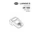
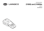
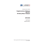
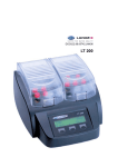
User Manual
DOC022.53.80400
Pocket Pro™ Salinity
1
Specifications
Specifications are subject to change without notice.
Specification
Details
Dimensions (W x D x H)
37 x 30 x 170 mm (1.45 x 1.18 x 6.69 in.)
Enclosure rating
IP67
Weight
135 g (0.297 lb) with batteries
Power requirements (internal)
AAA alkaline batteries (4x)
Battery life
450 hours
Operating temperature
0 to 50 °C (32 to 122 °F)
Storage temperature
–20 to 60 °C (–4 to 140 °F)
Operating humidity
80% (non-condensing)
Altitude
2000 m (6562 ft)
Instrument range
0.00 to 10.00 ppt
Resolution
0.01 ppt
Accuracy
±1% FS
Calibration points
1 point
Note: Temperature calibration is not available.
Auto-recognition calibration standard
12.88 mS/cm
Certifications
CE mark
Warranty
1 year for manufacturing faults only. Damage from use is not covered.
General information
In no event will the manufacturer be liable for direct, indirect, special, incidental or
consequential damages resulting from any defect or omission in this manual. The
manufacturer reserves the right to make changes in this manual and the products it
describes at any time, without notice or obligation. Revised editions are found on the
manufacturer’s website.
Safety information
NOTICE
The manufacturer is not responsible for any damages due to misapplication or misuse of this
product including, without limitation, direct, incidental and consequential damages, and disclaims
such damages to the full extent permitted under applicable law. The user is solely responsible to
identify critical application risks and install appropriate mechanisms to protect processes during a
possible equipment malfunction.
Please read this entire manual before unpacking, setting up or operating this equipment.
Pay attention to all danger and caution statements. Failure to do so could result in serious
injury to the operator or damage to the equipment.
Make sure that the protection provided by this equipment is not impaired. Do not use or
install this equipment in any manner other than that specified in this manual.
Use of hazard information
DANGER
Indicates a potentially or imminently hazardous situation which, if not avoided, will result in death
or serious injury.
2
WARNING
Indicates a potentially or imminently hazardous situation which, if not avoided, could result in
death or serious injury.
CAUTION
Indicates a potentially hazardous situation that may result in minor or moderate injury.
NOTICE
Indicates a situation which, if not avoided, may cause damage to the instrument. Information that
requires special emphasis.
Precautionary labels
Read all labels and tags attached to the instrument. Personal injury or damage to the
instrument could occur if not observed. A symbol on the instrument is referenced in the
manual with a precautionary statement.
This symbol, if noted on the instrument, references the instruction manual for operation and/or safety information.
Electrical equipment marked with this symbol may not be disposed of in European public disposal systems after
12 August of 2005. In conformity with European local and national regulations (EU Directive 2002/96/EC), European
electrical equipment users must now return old or end-of-life equipment to the Producer for disposal at no charge to
the user.
Note: For return for recycling, please contact the equipment producer or supplier for instructions on how to return end-of-life
equipment, producer-supplied electrical accessories, and all auxiliary items for proper disposal.
Certification
Canadian Radio Interference-Causing Equipment Regulation, IECS-003, Class A:
Supporting test records reside with the manufacturer.
This Class A digital apparatus meets all requirements of the Canadian InterferenceCausing Equipment Regulations.
Cet appareil numérique de classe A répond à toutes les exigences de la réglementation
canadienne sur les équipements provoquant des interférences.
FCC Part 15, Class "A" Limits
Supporting test records reside with the manufacturer. The device complies with Part 15 of
the FCC Rules. Operation is subject to the following conditions:
1. The equipment may not cause harmful interference.
2. The equipment must accept any interference received, including interference that
may cause undesired operation.
Changes or modifications to this equipment not expressly approved by the party
responsible for compliance could void the user's authority to operate the equipment. This
equipment has been tested and found to comply with the limits for a Class A digital
device, pursuant to Part 15 of the FCC rules. These limits are designed to provide
reasonable protection against harmful interference when the equipment is operated in a
commercial environment. This equipment generates, uses and can radiate radio
frequency energy and, if not installed and used in accordance with the instruction manual,
may cause harmful interference to radio communications. Operation of this equipment in
a residential area is likely to cause harmful interference, in which case the user will be
required to correct the interference at their expense. The following techniques can be
used to reduce interference problems:
3
1. Move the equipment away from the device receiving the interference.
2. Reposition the receiving antenna for the device receiving the interference.
3. Try combinations of the above.
Product overview
The Pocket Pro™ salinity tester measures the salinity of general water samples. Refer to
Figure 1. This tester is waterproof and floats.
Figure 1 Product features
1 Sensor cap
3 Keypad
5 Lanyard attachment
2 Sensor
4 Display
6 Pocket clip
Product components
Make sure that all components have been received. Refer to Figure 2. If any items are
missing or damaged, contact the manufacturer or a sales representative immediately.
4
Figure 2 Product components
1 Pocket Pro tester
3 Lanyard
2 AAA alkaline batteries (4x)
4 SINGLET™ (12.88 mS/cm)
Install the batteries
CAUTION
Explosion hazard. Incorrect battery installation can cause the release of explosive gases.
Be sure that the batteries are of the same approved chemical type and are inserted in the
correct orientation. Do not mix new and used batteries.
WARNING
Fire hazard. Battery substitution is not permitted. Use only alkaline batteries.
Install the four AAA alkaline batteries in the tester. Refer to the illustrated steps in
Figure 3.
Figure 3 Install the batteries
User interface and navigation
Display description
Figure 4 shows the measurements, calibration standard information and indicator icons
shown on the display. Table 1 gives descriptions of the icons.
5
Figure 4 Display overview
1 Calibration icon
4 Battery icon
7 Calibration standard expected1
2 Lock icon
5 Parameter value
8 Temperature
3 Parameter
6 Calibration standard measured for
last calibration (high)
1
Shows during calibration
Table 1 Display icons
Icon Description
Shows the battery power level. Flashes when the battery power is less than 10%.
Shows when the lock feature is on. When the lock feature is on, the parameter value on the display does not change.
Push to set the lock feature to on or off.
Shows when the tester is in calibration mode.
Keypad description
Figure 5 shows the keypad. Table 2 gives the key descriptions.
Figure 5 Keypad overview
1 Power key
6
2 Calibration/Settings key
3 Lock key
Table 2 Key functions
Key
Description
Push and hold to set the power to on or off.
Push to start a calibration. To exit a calibration, push and hold.
Push and hold until "SEt" shows on the display to go to the settings menu. To exit the settings menu, push and hold
until "End" shows on the display. When in the settings menu, push to scroll through the settings.
Note: Power cannot be set to off while in settings or calibration mode.
Push to set the lock feature to on or off. When the lock feature is on, the lock icon shows and the parameter value on
the display does not change.
Calibration
CAUTION
Chemical exposure hazard. Obey laboratory safety procedures and wear all of the
personal protective equipment appropriate to the chemicals that are handled. Refer to the
current safety data sheets (MSDS/SDS) for safety protocols.
Calibrate the tester before initial use and when:
•
•
Results drift
Results are not accurate
Before the initial calibration and after a dry storage, soak the sensor for several minutes
in the sample or tap water.
Calibrate
Items to collect: One auto-recognition calibration standard
1. Set the power to on.
2. Remove the cap from the sensor.
3. Push to go to calibration mode.
The auto-recognition standard(s) the tester expects to measure shows on the bottom
line.
4. Rinse the sensor and cap with deionized water and blot dry.
5. Pour the calibration standard shown into the cap to the fill line.
6. Put the sensor fully into the cap.
7. When the measurement is stable, push to save the calibration and go to
continuous measurement mode. The measured value will flash 3 times and then stop.
Then, "END" shows on the display.
8. Rinse the sensor and cap with deionized water and blot dry.
Measurement
Note: Air bubbles under the probe tip when submerged can cause slow stabilization or error in
measurement. Shake the tester from side to side to remove air bubbles.
1.
2.
3.
4.
5.
6.
Set the power to on.
Remove the cap from the sensor.
If the lock icon shows on the display, push to go to continuous measurement mode.
Rinse the sensor and cap with deionized water and blot dry.
Pour the water sample into the cap to the fill line.
Put the sensor fully into the cap. The measured value shows on the top line.
7
7. To keep the measured value on the display when the sensor is removed from the
sample, push .
Note: The lock icon shows on the display when the measurement is stable.
8. To measure another sample, do steps 3–7.
9. When done with measurements:
a. Rinse the sensor and cap with deionized water.
b. Put the cap on the tester.
c. Set the power to off.
Advanced operation
Configure the settings
1. Push and hold
until "SEt" shows on the display.
2. Push to scroll through the settings. The current value of the setting shows on the
bottom line.
Option Description
Unit
Select the temperature unit that shows on the display—Celsius (default) or
Fahrenheit.
Unit
Select the salinity unit that shows on the display— ppt or %.
AOFF
Set the auto-off feature to on (default) or off. When set to on, power is automatically
set to off after 8 minutes of no activity.
rSEt
Change the settings to the factory defaults—Yes or No (default). When set to Yes,
changes the settings to the factory settings and default values.
3. To change the value of the setting, push
4. When done with changes, push and hold
measurement mode.
or
.
until "End" shows to go to continuous
Maintenance
CAUTION
Multiple hazards. Only qualified personnel must conduct the tasks described in this
section of the document.
Clean the sensor
Clean the sensor when:
•
•
Stabilization is slow
Results drift or are not accurate
1. Soak the sensor in the applicable cleaning agent. Refer to Table 3.
2. Rinse or soak the sensor in deionized water for 1 minute.
Table 3 Cleaning agents
Contaminant
Cleaning agent
Time
Grease, oils and fats
Electrode cleaning solution
2 hours maximum
Mineral buildup
10% hydrochloric acid (HCl) solution
5 minutes maximum
8
Replace the batteries
When the battery icon flashes or the tester will not come on, replace all four batteries.
Refer to Install the batteries on page 5.
Troubleshooting
Message
"- - - -"
(top line)
"- - - -"
(bottom line)
Possible cause
Solution
The parameter value is not within the
measurement range of the tester. Refer to
Specifications on page 2.
Make sure that the value of the sample is within the
measurement range of the tester. Gently clean the
sensor. Refer to Clean the sensor on page 8. Calibrate
as necessary.
The temperature value is not within the
operating temperature range of the tester or
a temperature sensor failure occurred. Refer
to Specifications on page 2 for the operating
temperature range.
Make sure that the sample temperature is within the
operating temperature range of the tester. Contact
technical support as necessary.
Battery icon flashes The batteries have less than 10% power
remaining.
Note: The tester can still be used if a temperature sensor failure
has occurred, but without automatic temperature compensation.
Replace all four batteries. Refer to Install the batteries
on page 5.
Replacement parts
WARNING
Personal injury hazard. Use of non-approved parts may cause personal injury, damage to
the instrument or equipment malfunction. The replacement parts in this section are
approved by the manufacturer.
Note: Product and Article numbers may vary for some selling regions. Contact the appropriate
distributor or refer to the company website for contact information.
Table 4 Replacement parts
Description
AAA alkaline batteries
Lanyard
SINGLET, 12.88 mS/cm
Quantity
Item no.
4/pkg
4674300
1
201305
20/pkg
2771520
9
HACH COMPANY World Headquarters
P.O. Box 389, Loveland, CO 80539-0389 U.S.A.
Tel. (970) 669-3050
(800) 227-4224 (U.S.A. only)
Fax (970) 669-2932
[email protected]
www.hach.com
©
HACH LANGE GMBH
Willstätterstraße 11
D-40549 Düsseldorf, Germany
Tel. +49 (0) 2 11 52 88-320
Fax +49 (0) 2 11 52 88-210
[email protected]
www.hach-lange.de
Hach Company/Hach Lange GmbH, 2013. All rights reserved.
HACH LANGE Sàrl
6, route de Compois
1222 Vésenaz
SWITZERLAND
Tel. +41 22 594 6400
Fax +41 22 594 6499
09/2013, Edition 1