1
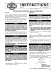
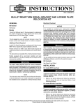
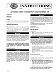
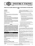
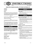
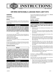
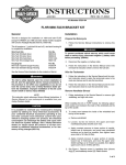
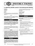
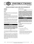
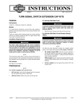
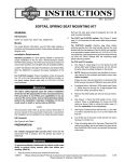
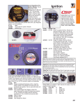
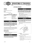
-J04588
REV. 2008-11-17
ROAD TECH ZUMO GLOBAL POSITIONING SYSTEM (GPS) FAIRING
MOUNTING KIT
Electrical Overload
GENERAL
Kit Number
92366-08
Models
This kit is required when using a Road Tech™ Zumo ™ GPS
unit on specific model motorcycles.
For model fitment information, see the P&A retail catalog or
the Parts and Accessories section of www.harley-davidson.com
(English only).
Additional Parts Required
A Road Tech Zumo GPS System Kit, part number 92357-08
is required. This item is available from a Harley-Davidson
dealer.
If the wires of circuit [29B] are already in use, a black-wire
multiple accessory harness (part number 70458-05) and an
orange/white-wire multiple accessory harness (part number
70459-05) will need to be purchased.These items are available
from a Harley-Davidson dealer.
For FLHT standard models without radio: See the P&A retail
catalog or the Parts and Accessories section of www.harleydavidson.com (English only) for a selection of Genuine Motor
Accessory ear bud speakers, helmet headsets or radio receiver
options that will allow use of the turn-by-turn voice instruction
feature of the Road Tech Zumo, or the XM satellite radio
capability (available separately).
It is possible to overload your motorcycle's charging
system by adding too many electrical accessories. If your
combined electrical accessories operating at any one time
consume more electrical current than your vehicle's
charging system can produce, the electrical consumption
can discharge the battery and cause vehicle electrical
system damage. See a Harley-Davidson dealer for advice
about the amount of current consumed by additional
electrical accessories, or for necessary wiring changes.
(00211b)
When installing any electrical accessory, be certain not
to exceed the maximum amperage rating of the fuse or
circuit breaker protecting the affected circuit being modified. Exceeding the maximum amperage can lead to electrical failures, which could result in death or serious injury.
(00310a)
The Road Tech Zumo requires up to 1.08A additional current
from the electrical system.
Kit Contents
See Figure 4 and Table 1.
INSTALLATION
Service Manual Required
The rider's safety depends upon the correct installation
of this kit. Use the appropriate service manual procedures.
If the procedure is not within your capabilities or you do
not have the correct tools, have a Harley-Davidson dealer
perform the installation. Improper installation of this kit
could result in death or serious injury. (00333a)
NOTE
NOTE
Do not use solvent-based chemicals or waxes directly on the
plastic or rubber components as they can affect the overall
performance and appearance of the plastic and rubber.
Installing the Mounting Bracket
1.
Refer to the service manual and follow the instructions
given to remove the main fuse.
2.
Remove the outer fairing and windshield. Refer to the
service manual.
This instruction sheet references service manual information.
A service manual for this model motorcycle is required for this
installation and is available from a Harley-Davidson dealer.
-J04588
1 of 5
Models WITHOUT radio: Obtain the power harness (F)
from the Road Tech Zumo GPS System Kit.
is05900
12. Insert the round 4-pin DIN connector (O) from the power
harness (and the audio cable end without the rubber boot,
if present) up through the 11/16 inch (17 mm) diameter
hole drilled earlier, so the connector (and cable end) are
sticking up out of the hole.
13. Install the grommet (7) around the harness (and cable
end), and insert the grommet into the hole. Leave
approximately 8 inches (200 mm) of the harness (and
audio cable) pointing rearward.
Figure 1. Road Tech Zumo Drilling Template Placement
3.
See Figure 1. Obtain the drilling template from the kit.
4.
Position the template on the back side of the inner fairing,
in the upper left corner above the fuel gauge, aligning the
template to the top of the inner fairing and the plastic rib
as shown.
14. Install the GPS mount and gasket over the harness (and
cable end). Direct the harness (and cable end) through
the hole in the mount. Be careful not to pinch the wires.
15. Fasten the GPS mount to the inner fairing with two 1/4-20
screws (4), flat washers (5) and locknuts (6). Tighten to
60-70 in-lbs (6.8-7.9 Nm)
Installing the Cradle
1.
Obtain the GPS cradle (B) from the Road Tech Zumo GPS
System Kit.
5.
Drill a 9/32 inch (7 mm) diameter hole through the inner
fairing per the template.
2.
6.
See Figure 4. Position the gasket (2) and GPS mount (1)
onto the face of the inner fairing, aligning the upper hole
in the mount with the hole drilled in the previous step.
Position the cradle to the GPS mount (1). Route the power
harness (and audio cable end) out through the slot in the
bottom of the mount.
3.
Insert a flat head screw (3) through one of the holes in the
cradle and into the corresponding hole in the GPS mount,
but do not fully tighten.
4.
Install the remaining three flat head screws. Incrementally
tighten the four screws to 14-20 in-lb (1.58-2.26 Nm).
5.
Plug the round four-pin DIN connector (O) on the Road
Tech Zumo power harness (F) into the front of the cradle
and fasten securely with the mounting screws (D).
7.
Temporarily install one of the screws (4) through the upper
hole to help align the GPS mount.
Mark the location of the lower mounting hole on the face
of the inner fairing, using the GPS mount and gasket as
a template. Mark the location of the wire routing hole using
the guide hole (S) in the gasket as a template.
8.
Remove the screw, GPS mount and gasket from the inner
fairing.
9.
Drill a 9/32 inch (7 mm) diameter hole through the inner
fairing in the lower mounting location.
For models WITH radio: Plug the 3.5 mm jack plug on
the audio cable into the AUX-IN port on the left side of the
GPS cradle under the rubber flap (P).
For models WITHOUT radio: Plug the 3.5 mm jack plug
on the earphone extension cable or helmet headset audio
cable (purchased separately) into the AUX-IN port on the
left side of the GPS cradle under the rubber flap (P).
Drill an 11/16 (17 mm) diameter hole through the inner
fairing in the wire routing location.
is05901
NOTE
2
The harness (and audio cable, if so equipped) lengths may
need to be adjusted by pulling more harness and cable through
the fairing.
1
Routing and Connecting the Wiring
1.
1. Gasket
2. Wire routing guide hole and ribs
See Figure 3, and the interconnect harness wiring diagram
in the service manual.
Proceed according to the availability of the black (1) and
orange/white (2) wires of the position lamp circuit [29B] of
the vehicle main harness, located near the headlamp:
Figure 2. Remove Gasket Ribs and Guide Hole
10. See Figure 2. Remove the wire routing guide hole and
four ribs (2) from the gasket (1).
11. Models WITH radio: Obtain the power harness (F) and
audio cable (G) from the Road Tech Zumo GPS System
Kit.
-J04588
2 of 5
If the wires of circuit [29B] are unused, and the female
tab connectors on the wire ends are intact:
NOTE
When installing the jack plug to the radio port socket:
a.
Remove the tape tying the black (1) and orange/white
(2) wires of circuit [29B] to the vehicle main harness.
•
Roll back the outer lip of the rubber seal.
•
b.
See Figure 4. Obtain the male tab terminals (9) and
housings (10) from the kit. Follow the service manual
instructions to crimp the terminals onto the free ends
of the Road Tech Zumo power harness (F). Insert a
terminal and wire into each tab housing.
Install the plug into the AUX port on the front of the radio
unit.
•
Gently roll the seal back to its original shape to form a seal
over the radio unit port.
Connect the red wire/tab housing from the power
harness to the orange/white wire and tab housing
from the unused circuit [29B].
4.
Plug the 3.5 mm stereo jack (with rubber boot attached)
on the audio cable into the AUX port on the front of the
radio.
5.
Use three cable straps (13) to keep the wires clear of
gauges and other items under the fairing.
6.
ALL models: Install the Road Tech Zumo GPS unit into
the cradle mount per the procedures that follow this section.
c.
d.
connect the black wire/tab housing from the power
harness to the black wire/tab housing of circuit [29B]
This will help eliminate "spring-back" of the plug out of the
socket.
If the wires of circuit [29B] are already in use:
a.
Disconnect any existing accessories from connector
[29B] of the vehicle main harness.
b.
See Figure 4. Obtain the multiple accessory Y-harnesses (items Q and R, purchased separately).
c.
d.
Connect the single-terminal end of each harness to
the corresponding color wire terminal on connector
[29B].
1
2
1. Black (ground) wire
2. Orange/ white wire
Figure 3. Wires for GPS Connection
3.
7.
Connect all accessories to the two available connectors on each Y-harness.
is00177
2.
NOTE
Verify that the ignition/light key switch is in the OFF position
before installing the main fuse.
Obtain one of the 2A fuses (11) from the kit (the second
is a spare), and open the cover of the fuse holder on the
GPS harness. Plug the fuse into the fuse holder, and close
the cover.
For models with radio: Route the audio cable (G) out of
the inner fairing through the hole for the handlebars. Use
a clip (12) to retain the cable along the inner fairing.
Verify that the ignition/light key switch is in the OFF position.
Refer to the service manual and follow the instructions
given to install the main fuse.
8.
Test the Road Tech Zumo unit for proper operation.
9.
Install the outer fairing and windshield. Refer to the service
manual.
ROAD TECH ZUMO UNIT INSTALLATION
TO CRADLE MOUNT
1.
See Figure 5. Obtain the Road Tech Zumo unit (A) from
the GPS Kit.
2.
Flip the lever (M) on the cradle mount (B) up. Flip the
weather cap (L) open.
3.
Position the Road Tech Zumo unit into the cradle mount,
and flip the lever (M) down.
4.
Use the security screwdriver (E) to tighten the security
screw (N).
5.
Plug the 3.5 mm jack plug on the earphone into the earphone extension cable, or the helmet headset audio cable
into the AUX-IN port on the left side of the GPS cradle.
ROAD TECH ZUMO UNIT OPERATION
NOTES
Do not use solvent-based chemicals or waxes directly on the
plastic or rubber components as they can affect the overall
performance and appearance of the plastic and rubber.
Refer to the instructions that came with the Road Tech Zumo.
-J04588
3 of 5
SERVICE PARTS
S
is05851
2
M
1
6
13
N
B
6
5
3
4
8
F
7
5
4
G
O
F
P
11
12
L
Q
9
10
A
R
Figure 4. Service Parts, Zumo GPS Fairing Mounting Kit
Table 1. Service Parts, Road Tech Zumo GPS Fairing Mounting Kit
Item
Description (Quantity)
Part Number
1
Fairing mount, Road Tech Zumo
92305-08
2
Gasket, Road Tech Zumo fairing mount
92320-08
3
Screw, hex socket, flat head, #8-32 x 1-1/4 inch (32 mm) long (4)
3098
4
Cap screw, hex socket, button head, 1/4-20 x 3/4 inch (19 mm) long (2)
923
5
Flat washer, 1/4 inch (6.4 mm) ID (4)
6703
6
Hex locknut, 1/4-20 (2)
7686
7
Grommet, split
11667
8
Drilling template
92391-08
9
Tab terminal, male, #14-18 AWG (2)
9853
10 Housing, tab terminal, male, one-way (2)
72053-92
11 Fuse, blade type, 2A (2)
54305-98
12 Clip, adhesive-backed (3)
10271
13 Cable strap (10)
10006
-J04588
4 of 5
SERVICE PARTS
is05802
E
C
G
D
M
N
O
B
A
F
L
H
Figure 5. Service Parts, Zumo GPS Unit Kit
Table 2. Service Parts, Road Tech Zumo GPS Kit
Kit
Item
Description (Quantity)
Part Number
Kit 92357-08
Road Tech
Zumo GPS
(must be purchased
separately)
A
Road Tech Zumo unit
Not sold separately
B
Cradle, Zumo GPS
Not sold separately
C
Cradle mount service kit (includes items D and E)
92379-08
D
•
Harness screw, M2 x 3.5 mm (2)
See garmin.com
E
•
Screwdriver, security
See garmin.com
F
Power harness assembly, Road Tech Zumo
See garmin.com
G
Audio cable
92389-08
H
Carrying case
92156-08
I
PCB/USB cable (not shown)
See garmin.com
J
A/C charger (not shown)
See garmin.com
K
User's manual, Road Tech Zumo (not shown)
See garmin.com
Reference items mentioned in text:
-J04588
L
Weather cap
M
Lever
N
Security screw
O
Round 4-pin DIN connector on harness (F)
P
Rubber flap (on left side of GPS cradle)
Q
Harness, multiple accessory (black wires) (separate purchase if needed) 70458-05
R
Harness, multiple accessory (orange/white wires)
(separate purchase if needed)
S
Wire routing guide hole (and ribs) in fairing mount gasket
70458-05
5 of 5