1
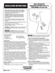
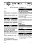
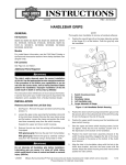
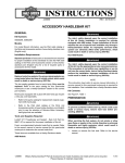
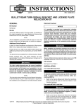
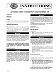
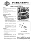
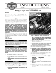
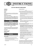
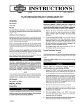
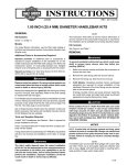
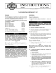
INSTRUCTIONS
®
REV. 06-24-2004
-J03277
Kit Number 76364-04
INSTALLATION KIT, RISER MOUNT RADIO, FXDL
General
Installation
This kit is required when installing a Riser Mount Radio (Part
Number 76360-03) on a 2001 or later FXDL (Dyna Low
Rider®) model motorcycle. The Riser Mount Radio is available
separately at any Harley-Davidson dealer:
1WARNING
To prevent accidental vehicle start-up, which could
cause death or serious injury, disconnect battery cables
(negative (-) cable first) before proceeding. (00307a)
This kit is not compatible with internally wired handlebars or
some accessories with conflicting mounting requirements.
See the Service Parts illustration for kit contents.
CAUTION
It is possible to overload your motorcycle’s charging
system by adding too many electrical accessories. If
your combined electrical accessories operating at any
one time consume more electrical current than your
vehicle’s charging system can produce, the electrical
consumption can discharge the battery and cause vehicle electrical system damage.
See a Harley-Davidson dealer for advice about the
amount of current consumed by additional electrical
accessories, or for necessary wiring changes. (00211b)
1WARNING
When installing any electrical accessory, be certain not
to exceed the maximum amperage rating of the fuse or
circuit breaker protecting the affected circuit being modified. Exceeding the maximum amperage can lead to
electrical failures, which could result in death or serious
injury. (00310a)
1WARNING
Disconnect negative (-) battery cable first. If positive (+)
cable should contact ground with negative (-) cable connected, the resulting sparks can cause a battery explosion, which could result in death or serious injury.
(00049a)
1. Refer to the Service Manual and the instructions for Riser
Mount Radio Kit 76360-03 to disconnect the battery
cables (negative cable first), and remove the battery from
the vehicle.
2. Drain the front brake system. See BLEEDING BRAKES
in the Service Manual.
NOTE
Cover the front fender and the front of the fuel tank with clean
shop towels to prevent scratching. Damage to the finish
could result.
3. Remove and discard the brake line that runs from the
front-brake master cylinder to the front-brake caliper.
See FRONT BRAKE MASTER CYLINDER in the
Service Manual.
This radio kit requires up to 1.5 amps additional current
from the electrical system.
1WARNING
Brakes are a critical safety component. Contact a
Harley-Davidson dealer for brake repair or replacement.
Improperly serviced brakes can adversely affect brake
performance, which could result in death or serious
injury. (00054a)
1WARNING
The rider’s safety depends upon the correct installation
of this kit. Use the appropriate Service Manual procedures. If the procedure is not within your capabilities or
you do not have the correct tools, have a HarleyDavidson dealer perform the installation. Improper
installation of this kit could result in death or serious
injury. (00333a)
NOTE
A Service Manual for your model motorcycle is available
from any Harley-Davidson dealer.
CAUTION
Do not remove or install the master cylinder assembly
without first positioning a 5/32-inch (4mm) thick insert
between the brake lever and lever bracket. Removing or
installing the master cylinder assembly without the
insert in place may result in damage to the rubber boot
and plunger on the front stoplight switch. (00324a)
NOTE
A small section of corrugated cardboard or the eyelet of an
ordinary cable strap can be used for this purpose.
4. See Figure 1. Squeeze the brake lever and place the
insert between the brake lever and lever bracket.
i03510
3
1
2
1. Brake lever
2. 5/32 inch thick insert
3. Brake lever bracket
Figure 1. Install Cardboard Insert
1 of 5
5. Using a T27 TORX drive head, remove the front-brake
master cylinder and clutch-lever assemblies (refer to
CLUTCH CABLE in the Service Manual) from the handlebar.
6. Using a T25 TORX drive head, remove the switch housings and attached wiring from the stock handlebar. Refer
to HANDLEBAR SWITCHES in the Service Manual.
Carefully set the switch assemblies on the towel-covered fuel tank.
7. Refer to the THROTTLE CONTROL section of the
Service Manual to disconnect the throttle cables from
the existing right grip/ throttle sleeve assembly.
8. See Figure 2. Remove the four hex socket head screws
(1) retaining the original equipment handlebar upper
clamp (2). Save the upper clamp for re-installation. The
screws can be discarded.
9. Remove and discard the original handlebar (3).
13. Install the rubber boot (2) from this kit over the original
equipment indicator lamp housing. Install the indicator
lamp assembly into the indicator bracket (1) from this kit.
NOTE
To make sure that the handlebar is centered, verify that the
knurled areas on the outboard side of each riser are equal.
14. See Figure 3. Place the new handlebar (2) onto the handlebar risers (1). In the sequence shown, attach the indicator bracket (6), along with the new riser mounting
plate (5) and spacers (4) from the radio kit, and the original equipment handlebar upper clamp (3) removed in
Step 8. Snug the upper screws, but do not fully tighten.
1WARNING
Improperly aligned handlebars can contact the fuel tank
when turned to the left or right. Contact with the fuel
tank while riding can cause loss of vehicle control
resulting in death or serious injury.
10. Remove and discard the hex head bolts (5) located
underneath the upper fork bracket. Remove and discard the stock handlebar risers (4). Save the remaining
hardware, taking note of the positioning and orientation
of each item.
15. Slowly turn the front wheel to the full right fork stop and
then the full left fork stop to be sure the handlebar does
not contact the fuel tank. If contact occurs and the handlebars are properly centered, raise the handlebar
angle as necessary until proper clearance is obtained.
11. See Figure 3 and the Service Parts illustration. Align the
new risers (17 and 18) from the kit, the saved cup
washers, bushings and spacers, and the ground wire
(on the right side only). Secure with two new hex head
bolts (19) and lockwashers (20) from the kit. Tighten to
50-60 ft lbs (68-81 Nm).
16. Tighten the upper handlebar-clamp screws as follows:
12. Remove the indicator lamps (A) from the headlamp
bracket. See INDICATOR LAMPS in the Service
Manual.
i02650
a. Tighten the front screws until the upper handlebar
clamps make contact with the handlebar riser.
b. Tighten the rear screws to 12-16 ft-lbs (16.3-21.7 Nm).
c. Tighten the front screws to 12-16 ft-lbs (16.3-21.7 Nm).
NOTE
There will be a slight gap between the upper clamps and the
risers toward the rear of the handlebars after tightening.
i02651
1
6
2
5
3
4
3
2
4
1
1
2.
3
4
5
Clamp screw (4)
Upper clamp
Handlebar
Handlebar riser
Hex head bolts (2)
5
Figure 2. Removing the Original Equipment Handlebar
-J03277
1.
2.
3.
4.
5.
6.
New riser (2)
New handlebar
Original upper clamp
Spacers from radio kit
Riser mounting plate from radio kit
New indicator bracket
Figure 3. Replacement Risers and Handlebar
2 of 5
1WARNING
Harley-Davidson Adhesive contains METHYL ETHYL
KETONE, a chemical known to the State of California to
cause cancer or other reproductive harm.
i05648
4
2
1WARNING
Use Harley-Davidson Adhesive in well ventilated areas
only. Vapors are flammable and can be harmful to breath.
Avoid contact with eyes, mucous membranes, or prolonged contact with skin. Keep out of reach of children.
3
1.
2.
3.
4.
License plate bracket
Ground strap
Antenna bracket
Antenna mounting surface
1
Figure 4. Antenna Mounting
17. Install the headlamp bracket trim (3) over the indicator
lamp opening in the headlamp bracket.
18. Complete the installation of the radio and mounting
brackets per the instructions in the radio kit.
19. Obtain the antenna bracket (4), antenna cable (6) and
ground strap (5) from this kit, and the antenna mounting
base (C) and antenna from the radio kit.
20. See Figure 4. Remove the fasteners holding the right
side of the license plate to the license plate bracket (1).
Discard the screw and nut, but retain the flat washers.
21. See the Service Parts illustration. Install the antenna
bracket (4) and ground strap (5) as shown, with the
antenna mounting surface toward the rear, using the
screw (E) and nut (F) from the radio kit, and the flat
washers (D) saved earlier.
20. Crimp the 5/16-inch ring terminal (7) from this kit onto
the other end of the ground strap. Attach that end of the
ground strap to the frame ground under the seat.
23. Obtain the new left hand handlebar grip (16) and the
adhesive (22) from this kit.
24. Apply a coat of adhesive to the inside surface of the grip
one inch (25.4 mm) from the open end. Apply a coat of
adhesive to the left end of the handlebar.
25. Immediately push the grip completely onto the end of
the handlebar using a twisting motion. Do not hesitate
when installing the grip or the adhesive may dry before
the installation is complete.
NOTE
At normal room temperature (70° F., 21° C), allow 6-8 hours
to elapse for the adhesive to fully cure.
26. Install the left-side handlebar switch controls. See HANDLEBAR SWITCHES, INSTALLATION in the Service
Manual.
27. Refer to the THROTTLE CONTROL section of the
Service Manual to re-install the throttle cables to the
original equipment right grip/ throttle sleeve assembly.
28. Install the right-side handlebar switch controls. See
HANDLEBAR SWITCHES, INSTALLATION in the
Service Manual.
29. Install the front-brake master cylinder. See FRONT
BRAKE MASTER CYLINDER in the Service Manual.
21. Complete the antenna installation and route the antenna
cable per the instructions in the radio kit.
22. Mount the radio and complete the installation per the
radio kit instructions.
-J03277
3 of 5
1WARNING
Replace brake-line gaskets. Re-using original gaskets
can cause brake failure and loss of vehicle control,
which could result in death or serious injury. (00318a)
CAUTION
Avoid leakage. Be sure gaskets, banjo bolt(s), brake line
and caliper bore are clean and undamaged before
assembly. (00321a)
30. Obtain the new front-brake line assembly (8) and new
steel/ rubber washers (9 and 10) from the kit, and install
them in place of the original equipment components.
CAUTION
Do not remove or install the master cylinder assembly
without first positioning a 5/32-inch (4mm) thick insert
between the brake lever and lever bracket. Removing or
installing the master cylinder assembly without the
insert in place may result in damage to the rubber boot
and plunger on the front stoplight switch. (00324a)
31. See Figure 1. Squeeze the brake lever, and remove the
insert between the brake lever and lever bracket.
32. Fill the brake master cylinder and bleed the brakes. See
BLEEDING HYDRAULIC BRAKES in the Service
Manual.
33. Obtain the new clutch cable (12) and anchor pin (13)
from this kit, and install them in place of the original
equipment. Refer to CLUTCH CABLE in the Service
Manual to re-install the clutch-lever assembly to the
handlebar.
1WARNING
Connect positive (+) battery cable first. If positive (+) cable
should contact ground with negative (-) cable connected,
the resulting sparks can cause a battery explosion, which
could result in death or serious injury. (00068a)
34. Refer to the Service Manual and follow the instructions
given to re-install the battery and attach the battery
cables (positive cable first).
-J03277
Safety Check
35. Turn the Ignition/Light Key Switch to IGNITION and test
each handlebar switch for proper operation.
36. Turn the handlebar to the left and right steering stops,
testing the handlebar control functions at each stop.
1WARNING
Wires and cables must not pull tight when handlebars are
turned fully to left or right fork stops. Be sure wires and
cables are clear of fork stops at steering head so they will
not be pinched when fork is turned against stops.
Steering must be smooth and free with no binding or
interference. Interference with steering could result in
loss of vehicle control and death or serious injury.
37. Apply the front brake hand lever to test operation of the
brake lamp.
38. Refer to the Service Manual, and follow instructions to
install the seat.
1WARNING
After installing seat, pull upward on front of seat to be
sure it is in locked position. While riding, a loose seat
can shift causing loss of control, which could result in
death or serious injury. (00070a)
1WARNING
Prior to starting engine, verify that the throttle control
will snap back to the idle position when released. A
throttle control that prevents the engine from automatically returning to idle can lead to a loss of control,
which could result in death or serious injury.
1WARNING
After servicing the brake system, test brakes at low
speed. If brakes are not operating properly, testing at
high speeds can cause loss of control, which could
result in death or serious injury. (00289a)
4 of 5
®
Part No. 76364-04
Service Parts
Date 06/04
Radio Installation Kit, FXDL
i02652
10
10
8
A
B
E
3
D
C
D
1
4
F
15
2
6
16
5
9
12
9
7
22
13
18
21
17
20
14
11
19
Item
1
2
3
4
5
6
7
8
9
10
11
12
13
14
Description (Quantity)
Bracket, indicator
Boot, connector housing
Headlamp bracket trim
(adhesive-backed)
Bracket, antenna
Strap, antenna ground
Cable, antenna
Terminal, ring, 5/16 in
Brake line assembly, front, single
Gasket, 0.37 in. I.D. (2)
Gasket, banjo, 0.43 in. I.D. (2)
Cable strap, 5.5 in (140 mm) (8)
Cable, clutch
Pin, anchor
“O”-ring
-J03277
Part No.
76193-03
69536-04
67834-83
76270-03
70462-03
76220-03
9859
45121-96
41731-88A
41733-88
10065
38661-00
45036-88
11179
Item
15
16
17
18
19
20
21
22
Description (Quantity)
Handlebar
Grip, handlebar (left)
Clamp, handlebar lower (riser) (right)
Clamp, handlebar lower (riser) (left)
Bolt, hex head,
1/2-13 x 2-3/4 in. long (2)
Lockwasher, split, 1/2 in.(2)
Retainer, wire
Adhesive
Part No.
56081-82A
56206-96
56542-86A
56541-86A
3471
7068
70345-84
99839-95
Items mentioned in text, but not in kit
A
Original equipment indicator lamps
B
Riser mounting plate from the Radio Kit
C
Antenna mounting base from the Radio Kit
D
Original equipment flat washers
E
1/4-20 screw from the Radio Kit
F
1/4-20 locknut from the Radio Kit
5 of 5