1
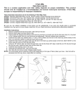
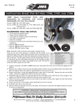
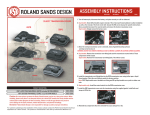
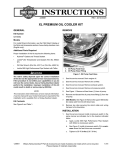
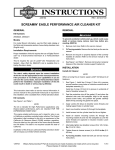
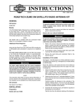
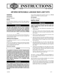
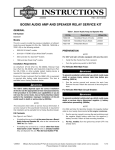
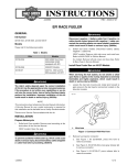
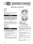
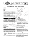
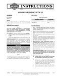
-J05041
REV. 2014-09-11
SOFTAIL SPRING SEAT MOUNTING KIT
Remove the seat, grab strap (if equipped) and rear tab
seat mounting hardware.
GENERAL
Kit Numbers
2.
54375-10, 54376-10A, 54377-10A, 52000014A
Models
For model fitment information, see the P&A retail catalog or
the Parts and Accessories section of www.harley-davidson.com
(English only).
Installation Requirements
Separate purchase of a Solo Spring Saddle is required for
proper installation of this kit. See a Harley-Davidson dealer,
the P&A retail catalog or the Parts and Accessories section of
www.harley-davidson.com (English only) for available saddles.
Loctite® 243 Medium Strength Threadlocker and Sealant-Blue
(Part No. 99642-97) is required for proper installation of this
kit.
For FXST and FLSTSB models: See Figure 6. Install
plug (17) in the fender hole left vacant after seat hardware
removal.
For FLST/C/N models: Remove one large plastic
retaining washer from the stud bracket. Secure the stud
bracket with two flat washers (Part No. 6235, not supplied)
or an equivalent washer stack with a 0.10-0.25 in (2.5-6.4
mm) thickness, and the previously removed seat mounting
nut (Part No. 3633). Repeat with the remaining large
plastic retaining washer.
For FXS and FLS models:
a.
See Figure 6. Install plug (17) in the fender hole left
vacant after seat hardware removal. Do not remove
the grab strap mounting hardware in the fender.
b.
NOTE: Electrical connectors are identified in the service manual by the numbers and letters shown here
within brackets.
For FLST/C/N models: Proper installation of this kit requires
four 1/4 in (6.4 mm) flat washers (Part No. 6235 or similar), or
two equal washer stacks, each with a 0.10-0.25 in (2.5-6.4
mm) thickness.
Follow service manual instructions to disconnect the
ECM harness connector [78B] and remove the ECM.
c.
If equipped with a "tall tower" ECM caddy (see Figure
1), follow steps 2d through 2h. If not equipped with
a tall tower caddy, proceed to Step 3.
d.
Remove the ECM caddy per service manual instructions.
e.
See Figure 1. Place the ECM caddy (3) on a firm
surface. Place a straightedge (2) across the ECM
caddy as shown. Mark or scribe the taller tower (1)
from the underside of the straightedge.
This instruction sheet refers to service manual information. A
service manual for this year/model motorcycle is required for
this installation and is available from a Harley-Davidson dealer.
f.
See Figure 2. Measure from the first line (1), and mark
or scribe a second line (2) 0.12 in (3 mm) above the
first line.
Kit Contents
g.
Cut off the top of the tower at the second line with a
hacksaw or similar tool.
h.
Clean all cutting debris from the tower. Place the ECM
caddy into position, but do not fasten into place at this
time. Install the ECM, but do not connect the harness
at this time.
The rider's safety depends upon the correct installation
of this kit. Use the appropriate service manual procedures.
If the procedure is not within your capabilities or you do
not have the correct tools, have a Harley-Davidson dealer
perform the installation. Improper installation of this kit
could result in death or serious injury. (00333a)
NOTE
See Figure 6 and Table 1.
PREPARATION
NOTE
For vehicles equipped with security siren: Verify that the
Hands-Free Fob is present. Turn the ignition key switch to
IGNITION.
To prevent accidental vehicle start-up, which could cause
death or serious injury, remove main fuse before proceeding. (00251b)
1. See the service manual and remove the main fuse.
-J05041
Many Harley-Davidson® Parts & Accessories are made of plastics and metals which can be recycled.
Please dispose of materials responsibly.
1 of 6
is07038
is07301
1
1
2
2
3
1. Tall tower
2. Straightedge
3. ECM caddy
7
Figure 1. Place Straightedge Across Caddy
9
2
is07037
1
3
5
6
8
1. First scribed line
2. 1/8 in (3 mm) distance
4
Figure 2. Cut Top of Tower
3.
For ALL models: See Figure 3. If not already done, disconnect the ECM connector [78B] (7) and tail lamp connector [7] (2).
4.
Remove the tail lamp connector (2) and data link connector
(9) from the T-studs.
NOTE
If the right-side ground cables cannot be relocated to the leftside ground location, they can be mounted to the right side
under the harness retaining bracket (8) later in the installation.
5.
Relocate the grounding cables as follows:
a.
Remove the right-side (5) and left-side (6) ground
screws.
b.
Secure all ground cables to the left-side ground location with the screw (6). Tighten the left-side screw to
90-110 in-lbs (10-12 Nm).
c.
-J05041
7
1.
2.
3.
4.
5.
6.
7.
8.
9.
ECM cover mounting hole
Tail lamp connector [7]
Pivot block mounting hole (2)
Spring saddle mounting bracket location (2)
Right-side ground screw
Left-side ground screw
ECM connector [78B]
Harness retaining bracket
Data link connector [91A]
Figure 3. Install Spring Saddle
Save the right-side ground screw for later installation.
2 of 6
All other models: See Figure 6. Apply Loctite 243-Blue
to the threads of screws (15). Install the spring saddle
mounting bracket (14) and two screws (15) over the
mounting flange of the ECM caddy, and fasten to the
vehicle frame. Tighten the screws to 96-120 in-lbs (11-13
Nm).
is06400
5
1
2
3
6
4
5
2
1.
2.
3.
4.
5.
6.
Screw, 5/16-18 x 3.5 in (89 mm) long
Washer, 5/16 in (7.9 mm) ID (2)
Pivot block
Pivot sleeve
Pivot bushing (2)
Hex nut
7.
NOTES
Before installing the lower frame cover, secure any remaining
right-side ground cables between the harness retaining bracket
(8) and the vehicle frame.
Move harnesses as necessary to allow the frame covers to
mount without interference. The ribs on the underside of the
lower frame cover should rest on the battery without pinching
the harness.
8.
See Figure 6. Install the lower frame cover (24) using the
right-side ground screw saved earlier. Tighten the screw
to 90-110 in-lbs (10-12 Nm).
9.
Install the upper frame (ECM) cover (18, 19, 22 or 23)
over the ECM. Align the cover so the lower tab fits into
the slot of the lower frame cover. Secure with the hex
socket button head screw (16) from the kit. Tighten the
screw to 60-90 in-lbs (7-10 Nm).
Figure 4. Pivot Block Assembly
FRAME COVER INSTALLATION
1.
See Figure 4. Press two pivot bushings (5) into the pivot
block (3) using one of the following methods:
Method 1, use a suitable press or vise, being careful to
protect bushing surfaces, or
Method 2, use the supplied hardware from the kit to seat
the bushings as follows:
a.
Install two bushings (5) into the pivot block (3) and
secure with the 3.5 in (89 mm) long screw (1), pivot
sleeve (4), two washers (2) and nut (6).
See Figure 3. Plug the ECM connector (7) into the ECM,
and mate the tail lamp connector halves (2).
SPRING SADDLE ASSEMBLY
1.
See Figure 5. Place the saddle (1) upside down on a clean
surface.
2.
Install each spring (2) to the seat as shown with a hex
socket flat head screw (3) from the kit, but do not fully
tighten at this time.
3.
b.
Tighten the nut to seat the bushings until there is face
contact with the pivot block.
c.
Remove the nut, screw, pivot sleeve and washers,
and save for later installation.
Align the springs so they are parallel to each other and
the seat. Verify that the springs are seated against the
metal seat pan under the edge of the leather. Secure the
saddle to the springs. See Figure 6.
2.
Get the two 1/4-20 x 5/8 in (16 mm) long hex socket head
screws from the kit (see Figure 6, Item 8). Apply Loctite
243-Blue to the screw threads.
Seats with 1/2 in hole: secure with screws (13). Tighten
the screws to 25-30 ft-lbs (34-41 Nm).
3.
See Figure 3. Fasten the pivot block to the mounting holes
at (3) with the screws from Step 2. Tighten the screws to
90-110 in-lbs (10-12 Nm).
4.
Remove screws at (4), if equipped. The screws can be
discarded or properly disposed of.
5.
FLST/C/N models: Install the clip nut (see Figure 6, Item
20) for upper cover installation.
6.
a.
Using a drill, enlarge the hole (Item 1, Figure 3) to a
diameter of 9/32-5/16 in (7-8 mm).
b.
Apply paint to any metal exposed during drilling to
prevent corrosion.
c.
Install the clip nut (item 20, Figure 6) over the sheet
metal edge of the ECM bracket and align the holes.
Seats with 3/8 in hole: secure with screws (26) and
spacers (25). Tighten the screws to 120-144 in-lbs (1416 Nm).
4.
Install the seat pivot bracket (4) to the seat as shown with
three hex socket head screws (6) and washers (5). The
bracket will sit on top of the leather at the front of the seat.
Center the screws in the bracket slots. Alternately tighten
the screws to 48-72 in-lbs (5.5-8.0 Nm).
FLST/C/N models: See Figure 6. Apply Loctite 243-Blue
to the threads of screws (15). Install the spring saddle
mounting bracket (14) over the two spacers (21) with the
two screws (15). Tighten the screws to 96-120 in-lbs (1113 Nm).
-J05041
3 of 6
is06403
3.
Position the front pivot bracket (9, assembled to the
saddle) over the pivot block.
4.
Install a washer onto the threads of the screw. Insert the
screw through the pivot bracket, a spacer, the pivot block
and sleeve, the remaining spacer and pivot bracket. Do
not install the nut or second washer at this time.
5
6
3
4
2
1
1.
2.
3.
4.
5.
6.
Saddle
Spring (2)
Flat head screw (2)
Pivot bracket
Washer, 1/4 in (6.4 mm) ID (3)
Screw, 1/4-20 x 1/2 in (12.7 mm) long (3)
NOTE
If the spring holes do not align with the rear seat bracket
mounting holes, loosen the front pivot bracket on the seat and
reposition until the seat and springs align properly. Tighten the
pivot bracket screws to 48-72 in-lbs (5.5-8.0 Nm). Repeat as
necessary.
5.
Pivot the seat over so the springs rest on the posts of the
rear seat mounting bracket (14, fastened to the vehicle
frame earlier). Position the seat so the springs align with
the mounting holes on the posts.
6.
See Figure 6. Secure the springs to the rear mounting
bracket with flat head screws (13). Tighten the screws to
25-30 ft-lbs (34-41 Nm).
7.
Secure the screw with the washer (2) and nut (6). Tighten
the nut and screw to 96-120 in-lbs (11-13 Nm).
Figure 5. Install Pivot Bracket to Saddle
SPRING SADDLE INSTALLATION
1.
2.
See Figure 6. Get the 3.5 in (89 mm) long screw (1), two
washers (2), the pivot sleeve (4), hex nut (6) and two pivot
spacers (7) from the kit. Insert the pivot sleeve into the
pivot block (3, mounted to the vehicle frame).
Apply Loctite 243-Blue to the threads of the long pivot
screw (1).
After installing seat, pull upward on seat to be sure it is
locked in position. While riding, a loose seat can shift
causing loss of control, which could result in death or
serious injury. (00070b)
8.
-J05041
See the service manual and install the main fuse.
4 of 6
SERVICE PARTS
17
FXST; FLST/C/N
FLSTSB
16
16
25
20
13
12
1
26
13
9
10
19
18
is06374c
12
11
8
FXS; FLS
FLSTF/FB
16
15
15
2
24
7
13
5
16
13
14
22
23
3
4
6
21
5
7
2
Figure 6. Service Parts: Softail Spring Seat Mounting Kit
Table 1. Service Parts
Item
Description (Quantity)
Part Number
1
Screw, hex socket button head, 5/16-18 x 3.5 in (89 mm) long
Not sold separately
2
Washer, 3/8 in (9.5 mm) ID x 13/16 in (20.6 mm) OD (2)
6400HB
3
Pivot block
52264-08
4
Pivot sleeve
9725
5
Pivot bushing (2)
52253-08
6
Hex nut, 5/16-18
7748W
7
Pivot spacer, nylon (2)
Not sold separately
8
Screw, hex socket head, with washer (SEMS), 1/4-20 x 5/8 in (15.9 mm) long (2)
3061
9
Pivot bracket
Not sold separately
10 Washer, 1/4 in (6.4 mm) ID x 3/4 in (19.0 mm) OD (3)
6253W
11 Screw, hex socket button head, 1/4-20 x 1/2 in (12.7 mm) long (3)
3063
12 Spring, seat (2)
Not sold separately
13 Screw, hex socket flat head, 1/2-13 x 1.0 in (25.4 mm) (4)
Not sold separately
14 Spring saddle mounting bracket
Not sold separately
15 Screw, hex flange head, self-tapping, 1/4-20 x 1.0 in (25.4 mm) (2)
939
16 Screw, hex socket button head, 1/4-20 x 3/4 in (19.0 mm)
923
17 Hole plug, for 0.406 in (10.3 mm) diameter hole (black)
761
18 ECM (upper frame) cover (for Kit 54375-10 only; FXST and FLSTSB models)
49801-10
19 ECM (upper frame) cover (for Kit 54376-10 only; FLST/C/N models)
49802-10
20 Clip nut, 1/4-20 (for Kit 54376-10 only; FLST/C/N models)
8108
21 Spacer, metal (2 - for Kit 54376-10 only; FLST/C/N models)
Not sold separately
22 ECM (upper frame) cover (for Kit 54377-10 only; FLSTF/FB models,)
49803-10
23 ECM (upper frame) cover (for Kit 52000014 only; FXS and FLS models,)
69200097
24 Lower frame cover
49800-10
-J05041
5 of 6
Table 1. Service Parts
Item
Description (Quantity)
Part Number
25 Spacer, seat support (2)
52100019
26 Screw, hex button head, 3/8 in (2)
10200368
-J05041
6 of 6