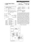
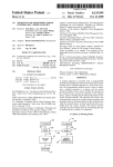
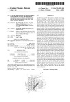
1
US005 95 8024A
Ulllted States Patent [19]
[11] Patent Number:
Typaldos et al.
[45]
[54]
5,958,024
Date of Patent:
SYSTEM HAVING A RECEIVE DATA
Sep. 28, 1999
OTHER PUBLICATIONS
Am186TMED/EDLV Microcontrollers
ASYNCHRONOUS SERIAL RECEIVER
[75]
User’s Manual,
Am186TMED,
Advanced Micro Devices,
High Inc.,
Performance,
80C186—and
80C188—C0mpatible, 16—Bit Embedded Microcontroller,
Advanced Micro Devices, Inc., Mar. 1997, pp. 1, 2, 13, 47
and 48
Inventors: Melanie D. Typaldos, Buda; Patrick E.
Maupin, Austin, both of Tex
Am186TMES and AmZ88TMES User’s Manual, Advanced
[73] Assignee: Advanced Micro Devices, Inc., Austin,
Micro Devices, Inc., 1997, pp. i through ii, 9—1 through
9—14, and 10—1 through 10—14.
Am186TMES/ESLVa'1dAmZ88TMES/ESLV>Advanced Micro
Devices, Inc., Publication 20002, Rev. B, Amendment /0,
Feb. 1997, pp. 1 through 12, pp. 25 through 52.
Tex~
Primary Examiner—Thomas C. Lee
[21] APPT- NOJ 08/920,930
-
_
[22] Filed.
Assistant Examiner—IlWoo Park
Attorney, Agent, or Firm—Akin, Gump, Strauss, Hauer &
Aug. 29, 1997
F61 d, LLP
[51]
Int. Cl.6 ........................... .. G06F 13/28; G06F 13/42
[52]
US. Cl. ................................. .. 710/26; 710/9; 710/14;
[58]
[57]
ABSTRACT
710/30; 709/221; 709/234; 711/156
An asynchronous serial port having a control register and at
Field of Search .......................... .. 324/312; 364/133;
least one data register exchanges data With a serial bus. The
370/438, 535; 375/220; 395/850, 250, 286,
309, 500, 566; 709/221, 234; 711/156;
asynchronous serial port includes an indicator representing
Whether the data register contains all of the data bits, or
710/9, 14, 26, 30
Whether some of the data may be stored in the control
register. When a nine-bit data source (or any data source
[56]
References Cited
having more than eight bits of data) is received, the bits need
not be divided among multiple registers, but can all be stored
U-S~ PATENT DOCUMENTS
in the receive-data register. This is particularly useful during
4 631 666 12/1986 Harris et al. .......................... .. 395/309
DMA or when the exchange of data has been Suspended> for
4698:5302 10/1987 Goke et aL
4,713,748 12/1987 Magar et a1_
370/535
395/566
example by an interrupt, While additional frames may be
received by the asynchronous serial port. Because frames are
4,785,396
4,823,305
11/1988 Murphy et a1, __
4/1989 Holdren et a1. ........ ..
395/286
395/850
stored in a single register When an extended Write bit or an
extended read bit is set. Further, the receive data register also
4,885,538 12/1989 Hoenniger, III et a1
4,972,432 11/1990 Wilson et al. ......... ..
571507359 9/1992 Wllson et a1‘
324/312
375/220
370/438
stores status bits associated With received data. This is
especially useful during DMA Operations, When Status,
including parity, frame, or overrun errors can be associated
2211:1320? a1‘
With a particular data item examining the stored DMA data
525481711
5,596,724
8/1996 Brant et a1. .... ..
1/1997 Mullins et a1. ..
395/182.03
395/250
5,812,820
9/1998 Loram ................................... .. 395/500
“Self
24 Claims, 7 Drawing Sheets
|— * - - — EXTENDED WHITE (EXDWR) \ 500
I
lr- - EXTENDED READ (EXDRD)\ 502
|
7
15
I I
506
I
I
I
I
I
I
I
A1466
I
I
I
I
I
I
|
|
504 \AnnREss BIT (AB)——‘
I
\AnnREss BIT ENABLE (ABEN) ------------------------ -
'
IHSPCTL
,- —————————————————— —-N0 DATA AVAILABLE (ND]\ 516
|
I
| ———————————— —— FRAMING ERROR (FER)\ 518
I
r ————————— —— nvERRuN ERR0R (0ER)\ 520
1
i
g
,- —————— —-PARITY ERR0R (PER)\ 522
|
1
|
|
|--"" MATCH (MATCH)\ 524
l
l
I
1
I
r’- ' BREAK (BRK)\ 526
15
7
I
I
I
f 54a
I
I
I
l
0
Ellllllll
14 \AnnREss BIT (AB) - J
IHSPRXR
l
|
|
|
l
l
512\REcElvEn DATA (RDATA) —----L--'---\---L--L--L--'---*
U.S. Patent
START
Sep.28, 1999
Sheet 2 of7
5,958,024
[9X9XMXWXMXDSICMAF
(PRIOR AR'D
FIG. 1a
_\START
4)
STOP
9
(PRIOR ART)
FIG. 1b
133
ASYNCHRONOUS SERIAL REGISTERS
CONTROL REGISTER
STATUS REGISTER
INTERRUPT CONTROL REGISTER
QQ
BAUD RATE DIVISOR REGISTER
RECEIVE REGISTER
TRANSMIT REGISTER
FIG. 3
gg
l
I 6
U.S. Patent
Sep.28, 1999
15
Sheet 4 0f 7
7
I I I I
48
RESERVED
l
602-J
I
604/BRKI ___I
606/3 RKO———
RB8 --'-
608/
I'l]
HDR
HRE‘
I
FIG. 5
U
7
I5
TI I I I I I I H I I I I I I
RDATA
RESERVED
FIG. 6
7
15
,
56
I I I I I I I
I I I I I I I
RESERVED
TDATA
FIG. 7
5,958,024
U.S. Patent
Sep.28, 1999
Sheet 6 of7
5,958,024
com
N
o
n
U
m
M UU
.UE:
w:
U.S. Patent
Sep.28, 1999
Sheet 7 0f 7
f 812
f- 800
INTERRUPT
SERVICE ROUTINE
802
INTERRUPT
SERVICE ROUTINE
814
READ
STATUS
816
OTHER I
PRDCES
RETURN
FROM ISR
FIG. 12A
FIG. 12B
5,958,024
1
2
SYSTEM HAVING A RECEIVE DATA
REGISTER FOR STORING AT LEAST NINE
DATA BITS OF FRAME AND STATUS BITS
INDICATING THE STATUS OF
ASYNCHRONOUS SERIAL RECEIVER
ends. This data rate is knoWn as the baud rate, Which is the
inverse of one bit period. The baud rate is generally one of
a number of prede?ned rates, Which are standard Within the
industry. Such rates include 1200, 2400, 4800, 9600, 192K,
288K, 333K, and 54K baud and high data transfer rates.
Due to the prevalence of serial data communication, many
BACKGROUND OF THE INVENTION
microcontrollers include one or more asynchronous serial
1. Field of the Invention
The apparatus and method according to the invention
pertains to microcontrollers, and more speci?cally, to a
ports (ASPs) Which can transmit and receive data one bit at
a time. Such microcontrollers typically employ interrupt
10
signals to notify the microprocessor core that an ASP
requires services. An ASP typically issues an interrupt
request signal When a data unit has been received by the ASP
microcontroller providing high asynchronous serial port
data rates using direct memory access.
and needs to be transferred from the ASP to an external
2. Description of the Related Art
memory unit, When the ASP is ?nished transmitting a data
Although consumers readily recogniZe the impact of
personal computers in our society, they may be less aWare of
unit and the next data unit to be transmitted must be
transferred from the external memory unit to the ASP, or
other manifestations of microcomputers Within everyday
When an error occurs.
life. Industrial and consumer products often require dedi
cated intelligence of their oWn, and to this end, the same
technology that poWers a personal computer has found its
Way into everyday industrial and consumer goods, such as
cellular phones, televisions, stereo systems, and a Wide
An ASP can be con?gured for a variety data formats,
although historically seven or eight data bits are typical
values. A number of nine-bit serial protocols, hoWever, have
20
been developed using microcontrollers, including a nine-bit
asynchronous serial protocol in conjunction With direct
variety of other products. Similarly, scienti?c
instrumentation, communications systems, and control sys
tems invariably include microcontrollers.
memory access. Such protocols are described in US. patent
25
A centerpiece of this technology is knoWn as a
microcontroller, or embedded controller, Which in effect is a
microprocessor as used in a personal computer, but With a
great deal of additional functionality combined onto the
same monolithic semiconductor substrate (i.e., chip). In a
application Ser. No. 08/807,103, now US. Pat. No. 5,896,
549, entitled “System for selecting betWeen internal and
external DMA request Where ASP generates internal request
is determined by at least one bit position Within con?gura
30
typical personal computer, the microprocessor performs the
tion register”, ?led Feb. 4, 1997, by John P. Hansen, Louis
R. Stott, and Melanie D. Typaldos, and US. patent appli
cation Serial No. 08/775,262, entitled “A Microcontroller
Having HardWare Features Supporting 9-Bit Serial Proto
basic computing functions, but other integrated circuits
cols During DMA Data Transfers to and from one or more
perform functions such as communicating over a network,
Asynchronous Serial Ports,” ?led Feb. 4, 1997, by John P.
controlling the computer memory, and providing input/
output With the user.
In a typical microcontroller, many of these functions are
35
reference. These protocols are also described in the
Am186ES Users Manual and Am186ED Users Manual, both
embedded Within the integrated circuit chip itself. A typical
by Advanced Micro Devices, Inc. of Sunnyvale, Calif. As
microcontroller, such as the Am186EM or AM186ES by
Advanced Micro Devices, Inc., of Sunnyvale, Calif., not
only includes a core microprocessor, but further includes a
memory controller, a direct memory access (DMA)
described in those applications, and as discussed beloW, a
40
grated circuits, requiring a larger area and increasing the siZe
of the product. By embedding these functions Within a single
chip, siZe is dramatically reduced, often important in con
separate control bit is set or reset to act as the ninth data bit
during transmission and reception of data. To support DMA
using such 9-bit protocols, When that particular bit is
controller, an interrupt controller, and both asynchronous
and synchronous serial interfaces. In computer systems,
these devices are typically implemented as separate inte
Hansen, Ronald W. Stents, and Melanie D. Typaldos, both of
Which are commonly assigned and hereby incorporated by
received as a certain value, an interrupt is caused to indicate
that the ninth data bit has in fact been set.
45
Expanded functionality, hoWever, in providing asynchro
nous communication using direct memory access and in
providing data bits greater than a standard eight data bits is
alWays desirable.
sumer products.
From a consumer products designer’s vieWpoint, often the
SUMMARY OF THE INVENTION
particular combination of added features make a particular
microcontroller attractive for a given application. Many
According to the invention, standard serial receive and
microcontrollers are available that use the standard 80x86
transmit registers are modi?ed to hold extended data. Rather
microprocessor instructions, alloWing for softWare to be
easily developed for such microcontrollers. Because of the
than providing eight data bits in the receive and transmit data
55
similar execution unit instruction sets, the added features
registers and then providing the ninth data bit in a status or
control register, When the extended mode according to the
often become principal differentiating criteria betWeen par
invention is enabled, all nine transmit or receive data bits are
ticular microcontrollers.
An asynchronous serial communications port is one such
placed into a 16-bit transmit or receive register. Then, Word
Wide DMA Writes and reads can properly send and receive
common additional feature in a microcontroller. An asyn
chronous serial link alloWs the microcontroller to commu
60
nicate With other devices or over data lines by sequentially
sending and receiving bits of data. The “asynchronous”
nature indicates these ports do not provide a separate clock
signal to clock the data. Instead, the rate at Which data is sent
and received must be predetermined or prenegotiated, and
independently controlled on both the sending and receiving
all nine data bits simultaneously, rather than requiring inter
rupt When the ninth data bit is set.
65
Further, the extended receive data register also includes
certain helpful status bits associated With the data actually
received Within the high order byte of the data. In addition
to the ninth data bit, match detect, overrun, break, frame
error, and parity error values are all held in the high order
byte of the 16-bit receive register. Thus, DMA reads not only
5,958,024
3
4
read data from the asynchronous serial port, but read the
status associated With that data. This is helpful in providing
DETAILED DESCRIPTION OF THE
PREFERRED EMBODIMENT
a correspondence betWeen any particular data errors and the
data item Which caused the error. This prevents the need for
an interrupt on an error condition, Which could ultimately
result in an overrun condition if the interrupt service routine
Turning to FIG. 1, shoWn is a block diagram of a typical
microcontroller M implemented according to the invention.
Such a microcontroller is preferably implemented on a
could not service the serial port quickly enough.
single monolithic integrated circuit. The microcontroller M
Additionally, as the DMA data is received and stored, the
asynchronous status register accumulates any errors that
preferably includes an internal bus 100 coupling a variety of
functional units and registers used to control and monitor
those units. These include a clock and poWer management
might occur. The status register error bits are only reset When
10
read, so an error on any of the DMA transfers Will set the
corresponding status bit for the remainder of the DMA Then,
softWare can ?rst check the status register. If it has no errors
set, the DMA occurred Without error. Only if an error
occurred is it necessary to examine the memory Where the
status bits Were stored along With the received data.
15
When used With DMA, the nine bit single data reading
according to the invention also prevents the need to provide
separate interrupt code to “?x” the data in memory When the
a programmable input/output (PIO) unit 132 With corre
sponding PIO registers 134, an asynchronous serial port 136
With corresponding asynchronous register 138, and a syn
chronous serial port 140 With corresponding synchronous
interrupt. Instead, the DMA itself handles the transfers of the
ninth bit.
The techniques according to the invention is further useful
registers 142. The clock and poWer management unit 102
includes external pads connected to a crystal 144, Which
even When DMA is not used to access the serial port. If the 25
execution unit polls the serial port, providing all nine data
bits in a single read or providing the status bits With the data
bits both reduce the number of serial port reads necessary to
obtain data and status. This is especially bene?cial at high
data rates, Where serial port reads can absorb a signi?cant
portion of the execution units bandWidth.
All of these features are especially helpful in high speed
provides the timing not only for the execution unit 124, but
also for generating the serial clock in the asynchronous
serial port 136.
The block diagram of the microcontroller M is typical of
microcontrollers, and could be for example, the Am186EM
microcontroller by Advanced Micro Devices, Inc., of
Sunnyvale, Calif. The techniques and circuitry according to
the invention, hoWever, could be applied to a Wide variety of
microcontrollers. Further, the term “microcontroller” has
differing de?nitions in industry. Some companies refer to a
asynchronous communications.
35
processor core With additional features (such as I/O) as a
“microprocessor” if it has no onboard memory, and digital
signal processors (DSPs) are noW used for both special and
general purpose controller functions. So as here used, the
obtained When the folloWing detailed description of the
preferred embodiment is considered in conjunction With the
term “microcontroller” covers all of the products, and gen
erally means an execution unit With added functionality all
implemented on a single monolithic integrated circuit.
In many cases, a microcontroller containing an asynchro
folloWing draWings, in Which:
FIG. 1 is a block diagram of a typical microcontroller in
Which the techniques according to the invention can be
implemented;
nous serial port is con?gured to begin receiving asynchro
FIG. 1A is a diagram of a data frame used in asynchronous
serial communications;
FIG. 2 is a DMA unit block diagram illustrating a DMA
unit With tWo DMA channels in the microcontroller of FIG.
isters 108, a timer control unit 110 With corresponding timer
registers 112, a direct memory access (DMA) unit 114 With
corresponding DMA registers 116, a bus interface unit 118
With corresponding bus interface registers 120, an execution
unit 124 Which is essentially a microprocessor core, a chip
select unit 126 With corresponding chip select registers 128,
ninth bit is set. It also eliminates the need to recon?gure or
restart the DMA that may have been terminated by the
BRIEF DESCRIPTION OF THE DRAWINGS
A better understanding of the present invention can be
unit 102 With corresponding clock/power registers 104, an
interrupt control unit 106 With corresponding interrupt reg
45
nous data via the asynchronous serial port 136. It Will be
recogniZed that the execution unit 124 of the microcontroller
M executes instructions of softWare programs. The micro
controller M can be con?gured to cause an interrupt from the
1;
asynchronous serial port 136 When an asynchronous device
sends data to the microcontroller M. That interrupt is then
interpreted by the interrupt control unit 106 on the internal
bus 100. Upon receiving an interrupt, the execution unit 124
stops program execution, saves the contents of certain
FIG. 3 is a block diagram illustrating typical asynchro
nous serial registers in the microcontroller of FIG. 1;
FIG. 4 is a block diagram illustrating bits Within a serial
port control register of the serial port registers of FIG. 3;
FIG. 5 is a block diagram illustrating bits of a serial port
critical registers (i.e., saves its internal state), and begins
executing instructions of an appropriate interrupt service
status register of the serial port registers of FIG. 3;
FIGS. 6 and 7 are typical receive and transmit registers
historically used as part of the asynchronous serial registers
of FIG. 3;
FIG. 8 is a high speed serial port control register including
additional features according to the invention;
FIGS. 9 and 10 are high speed serial port transmit and
receive data registers extended according to the invention;
55
routine (such as an interrupt handler) associated With the
asynchronous serial port 136. When execution of the inter
rupt service routine is completed, the execution unit 124
restores the saved contents of the critical registers (i.e.,
restores the internal state) and resumes execution of the
interrupted program at the point Where the interruption
occurred.
FIG. 11 is a diagram illustrating the use of the extended
ASYNCHRONOUS COMMUNICATION
PROTOCOL
receive data register according to the invention in conjunc
tion With direct memory access; and
FIG. 12A and 12B are ?oWcharts illustrating interrupt
service routines according to both the prior art and the
invention.
65
Asynchronous serial communication is a standard means
of transmitting data over distances greater than about 25
feet. In serial data communication, each unit of data (e.g., an
5,958,024
5
6
8-bit byte representing the character) is transmitted one bit
registers 138. The asynchronous serial port registers 138
at a time over a transmission medium (e.g., a pair of Wires,
a coaxial cable, etc.). Asynchronous communication can
begin With a communication “handshake” during Which the
include a control register 46, a status register 48, a baud rate
divisor register 52, a receive register 54 also referred to as
a receive data register, and a transmit register 56 also
sender and the receiver of communication negotiate a set of
rules for communicating data. The set of rules can include
referred to as a transmit data register. In some
the speed at Which information Will be transferred, the
number of bits per frame, and the format of any overhead
information, as Well as other matters. A “frame” of data
typically includes a sequence of consecutive data bits,
possibly together With one or more overhead bits. Overhead
10
bits include any start bits and stop bits, and de?ne any parity
bits that may be used.
Referring noW to FIG. 1A, a diagram of a data “frame”
microcontrollers, an interrupt control register 50 is also
included. In multiple ASP microcontrollers, each of these
registers exist for each of the serial ports.
The ASP 136 is typically bidirectional, i.e. is capable of
both sending data and receiving data. The status register 48
operates in conjunction With the receive register 54 When the
port 136 receives data, and operates in conjunction With the
transmit register 56 When the port 136 sends data.
used in asynchronous serial communication is shoWn. Dur
ing each frame, data is digitally transmitted by sending a
15
start bit, a number of data bits and possibly one or more
Referring noW to FIG. 4, a serial port control register 46
is shoWn. The serial port control register 46 contains 16 bits,
parity bits, and a stop bit from the sender to the receiver.
Thereafter, additional frames are also transmitted. The data
frame includes multiple data bits 2 transmitted betWeen a
start bit 4 and one or more stop bits 6. Data bits 2 include
20
n bits of data unit, DO through Dn_1, Where n is typically 7
or 8, and an optional parity bit 8 Which may be added to
facilitate error detection. The start bit (invariably 0) is
typically transmitted before the ?rst character bit, and one or
more stop bits (invariably 1) are transmitted after the last
character bit. The start bit 4 signals the beginning of the
frame, and the one or more stop bits signal the end of the
frame. The start bit 4 and the stop bits 6 are used to
synchroniZe a transmitter and a receiver during asynchro
nous serial communication. The transmitter and receiver
SERIAL PORT CONTROL REGISTER
numbered according the radix notation in Which the bits are
[15:0]. Bits [15:13] 302 are the DMA control bits for the
particular serial port. Bit [12] 304 is an RSIE bit, the Receive
Status Interrupt Enable bit, Which enables the serial port to
generate an interrupt request When an exception occurs
25
during data reception. Bit [11] 306 is a BRK bit, for sending
abreak signal. Bit [10] 308 is the “transmit bit 8 (TB8)”
indicator, storing the ninth data bit in modes tWo and three.
As explained beloW, mode 2 alloWs 9-bit communication,
and mode 3 alloWs either 8- or 9-bit communication. Bit [9]
310 is a Flow Control Enable bit. Bit [8] 312, the transmit
30
ready interrupt enable (TXIE) bit, commands an interrupt
must both use the same set of rules designating hoW many
request Whenever a transmit holding register is empty and
bits are transmitted per second (i.e., the baud rate), hoW
many bits are included in a data unit, Whether a parity bit is
included, and hoW any stop bits are added after the data bits.
Microcontrollers have been implemented that can operate
in 7, 8, or 9-bit serial protocols to transfer data using
35
generate transmit interrupt requests at all.
Bit [7] 314 is the Receive Data Ready Interrupt Enable
(RXIE) bit, Which causes the asynchronous serial port 136
the bit is set. When the bit is reset, the serial port does not
to generate an interrupt request Whenever the receive reg
ister contains valid data and the RXIE bit is set. Bit [6] 316
indicates Whether the transmit section of the serial port is
asynchronous serial communication. In some systems, a
header byte or header frame has included the number of data
bits transmitted per succeeding data frame, alloWing use of
the ninth bit of each succeeding data frame to be used for
enabled and able to generate interrupt requests. Bit [5] 318
40
indicates Whether the receive section of the serial port is
45
enabled and able to generate interrupt requests. Bit [4] 320,
the even parity (EVN) bit, commands even parity checking
When set, and odd parity checking When reset. Bit [3] 322,
the parity enable (PE) bit, enables parity checking When set.
Bits [2:0] 324 indicate the mode of operation. Mode 1
parity (i.e., simple error detection techniques). In other
systems, the ninth bit of data has been used to indicate the
?nal frame in a series of frames, such that the ninth bit is 0
in each of the frames except for the last frame, While in the
last frame the ninth bit is set to 1. Nine-bit serial protocols
are commonly used to manage communications betWeen
multiple microcontrollers coupled to a common transmis
sion medium. In such a case, each data packet typically
alloWs either 7 or 8 data bits per frame, With either 1 or 0
parity bits and one stop bit. Mode 2 alloWs 9 data bits per
frame and one stop bit. Parity is disabled, since the parity bit
includes one or more “header” frames at the beginning of the
data packet. Each data packet may also include one or more
is used for data. Mode 3 alloWs either 8 or 9 data bits per
frame and one stop bit. Either 1 or 0 parity bits are used. As
“trailer” frames at the end of the data packet. One of the
header frames typically includes a unique device identi?ca
tion (ID) number assigned to the intended receiver. The
trailer frames may include, for example, the last data units
of the data packet or a cyclic redundancy check (CRC) value
stated, in modes 2 and 3, nine data bits are supported. In
mode 2, the serial port receiver Will not complete a data
reception unless the ninth data bit is set (high). Any char
acter received With the ninth data bit reset (loW) is ignored.
The transmit portion of the port behaves identically With the
mode 3 operation. Mode 2 can be used in conjunction With
55
for error detection. In FIG. 1B, a ninth data bit 9 is set to 1
in the header and trailer frames and is set to 0 in other data
mode 3 to alloW for multidrop communications over a
common serial link. The serial port is con?gured as mode 2
packet frames.
When operating under a 9-bit protocol, the loWest-order
eight bits (bits 7:0) are transmitted in a data byte, and the
ninth bit (bit 8) is transmitted in place of the parity bit. Such
a protocol is illustrated in FIG. 1B, Where the ninth bit 9
folloWs the initial eight data bits.
60
initially. Each time data is received With the ninth bit set, the
data is compared by softWare against a unique ID for this
receiver. If the received data does not match the port ID, the
port is left in mode 2. If the received data matches the port
ID, softWare recon?gures the serial port to mode 3, alloWing
it to receive 9-bit data With the ninth bit reset. Mode 4 alloWs
ASYNCHRONOUS SERIAL PORT REGISTERS
As shoWn in FIG. 1, and as further shoWn in FIG. 3, the
typical microcontroller M includes asynchronous serial port
65
only 7 data bits and 1 stop bit, and parity is disabled.
Although modes 0, 5, 6, and 7 are de?ned, these modes are
reserved.
5,958,024
8
7
transmit register 56. Each of these registers is capable of
storing data in the loWer-order byte (bits [710]) of the
In a serial multidrop con?guration, multiple serial ports
are attached to the same serial line. The master serial port is
con?gured in mode 3 While the slave serial ports are
respective register, While the upper-order byte (bits [15 :8])
con?gured in mode 2. The master polls the other devices by
sending out status request packets. Each of these status
request packets begins With an address byte (i.e., ninth data
bit is set). The slave ports report a receive character for the
address byte since the ninth bit is set. Each port then
has historically been reserved. The microcontroller M is
typically able to exchange data in the receive register 54 and
the transmit register 56 With various memory units, accord
ing to the softWare running in the execution unit 124.
attempts to match the address against its oWn address. If the
addresses do not match, the port remains in mode 2 and
ignores the remainder of the message. If the addresses
When data is received by the asynchronous serial port
136, the data is initially stored in the receive register 54. The
10
match, softWare recon?gures the port into mode 3. The tWo
mode 3 ports are able to exchange data freely.
Only ports Which are actively exchanging data (i.e., ports
in mode 3) have hardWare handshaking enabled. Thus,
15
microcontroller M is also typically able to transmit data in
the transmit register 56. Whether the data in the receive
register 54 and the transmit register 56 are valid is deter
mined by examining the status register 48. Bit [7] 610 of the
status register 48 (see FIG. 6) is the read-only Receive Data
Ready (RDR) bit indicating Whether the receive data register
multiple devices may not be driving the hardWare handshak
ing lines. HardWare handshaking is not supported for the
mode 2 con?guration and is not enabled. Nor is hardWare
bit, indicating Whether the transmit holding register 56 is
handshaking enabled When more than tWo devices may be
ready to accept data for transmission.
54 contains valid data. Bit [6] 612 of the status register 48
is the read-only Transmit Holding Register Empty (THRE)
con?gured as mode 3 at any one time.
DMA AND EXTERNAL DEVICES
Mode 3 supports 8 data bits When parity is enabled and 9
data bits When parity is disabled. Historically, When not
As shoWn in FIG. 1, a typical microcontroller includes a
DMA Unit 114. Direct memory access (DMA) is a Well
using parity, the ninth bit (bit 8) for transmission is set by
Writing a 1 to the TB8 ?eld in the serial port control register.
The ninth data bit for the receive is then read in the RB8 ?eld
25
of the serial port status register. In multidrop
communications, parity is disabled, and the softWare inter
microcontrollers include a DMA unit Which controls DMA
data transfer operations. The execution unit 124 simply
initialiZes control registers Within the DMA unit 114 With
transfer control information. The transfer control informa
tion typically includes the ?rst address at the source of the
block of the data to be transferred (i.e., the source address),
the ?rst address of the destination of the block of data to be
prets receive characters as data as long as the ninth data bit
is reset (loW). When a character is received With the ninth bit
set, softWare compares the loWer eight bits against the port
ID. If the port ID matches the receive data, the port remains
in mode 3. OtherWise, the port is recon?gured as mode 2.
SERIAL PORT STATUS REGISTER
Referring to FIG. 5, a serial port status register 48 is
shoWn. The serial port status register 48 is a 16-bit memory
35
request signal by gaining control of the common bus inter
connecting the involved devices and initiating the data
transfer operation. The DMA unit generates address and
control signals needed to read a byte or Word of data from
the source address and to Write the data to the destination
address. After each read/Write operation, the source and
destination addresses and the byte/Word count may be
45
Bit [7] 610 is a read-only Receive Data Ready (RDR) bit
indicating Whether the Receive Data register contains valid
data. Bit [6] 612 is a read-only Transmit Holding Register
Empty (THRE) bit, indicating Whether the transmit holding
register is ready to accept data for transmission Bit [5] 614
has detected an overrun error, Which occurs When the serial
Referring noW to FIG. 2, a DMA unit 114 block diagram
shoWing tWo high-speed DMA channels. Data transfer can
occur betWeen memory and I/O spaces (e. g., memory to I/ O)
55 or Within the same space (e.g., memory to memory or I/O to
I/O). Each of the DMA channels can be directly connected
to the asynchronous serial ports. The DMA unit 114 can be
programmed to perform transfers betWeen the data source in
memory or I/O space in the serial port transmit or receive
register, thus permitting DMA to serial port transfers. Either
data to transmit, and that it is safe to disable the transmit
section. Bit [1] 622 is an inverted version of an external
bytes or Words can be transferred to or from even or odd
addresses.
Each channel has six registers in a peripheral control
signal, and Bit [0] 624 is reserved.
SERIAL PORT TRANSMIT AND RECEIVE
REGISTERS
Referring noW to FIGS. 6 and 7, the asynchronous serial
port 136 also contains the receive register 54 and the
incremented or decremented. (The source/destination
address pointing to the serial port, hoWever, is not incre
mented or decremented, since the serial port is accessed
through a ?xed address.) This process is continued until the
data transfer operation is complete. When the data transfer
operation is complete, the DMA unit 114 relinquishes con
trol of the common bus.
indicates Whether the serial port has detected a framing error,
Which occurs When the serial port receiver attempts to read
a stop bit as data. Bit [4] 616 indicates Whether the serial port
port loses data by overWriting valid but unread data in the
receive register. Bit [3] 618 indicates Whether a parity error
has been detected (in mode 1 or 3). Bit [3] 618 is reset by
softWare. Bit [2] 620 is the read-only Transmitter Empty
(TEMT) bit, Which indicates Whether the transmitter has no
transferred (i.e., the destination address), and the number of
bytes of Words to be transferred (i.e., the byte/Word count).
When a device needs to transfer data, the device generates
a DMA request signal. The DMA unit responds to the DMA
mapped register. Bits [15:11] 602 are reserved. Bit [10] 604
indicates Whether a long break is detected on the asynchro
nous serial interface. Bit [9] 606 indicates Whether a short
break is detected on the asynchronous serial interface. Bit
[8] 608 contains the ninth data bit, When 9 data bits are
transmitted. As discussed in reference to the serial port
control register 46, 9 data bits are transmitted When the
asynchronous serial port 136 is in mode 2 or mode 3. Bit [8]
608 is reset by softWare.
knoWn technique Which alloWs data transfers Without requir
ing continuous action by the execution unit 124. Many
block that de?nes speci?c channel operations. The DMA
65
registers 116 consist of a 20-bit source address (tWo
registers), a 20-bit destination address (tWo registers), a
16-bit transfer count register, and a 16-bit control register.
5,958,024
10
The DMA transfer count register (DTC) speci?es the num
ber of DMA transfers to be performed. The DMA control
registers de?ne the channel operation. The DMA control
When these bits are false, the ASP 136 acts as described in
registers specify, for example, the mode of synchronization,
Serial Protocols During DMA Data Transfers to and from
the previously incorporated application entitled “A Micro
controller Having HardWare Features Supporting 9-Bit
Whether bytes or Words are transferred, Whether an interrupt
one or more Asynchronous Serial Ports.” When the extended
is generated after the last transfer, Whether DMA activity
Write bit 500 is true, hoWever, the transmit register 56 is
modi?ed to instead transmit nine data bits, and When the
extended read bit 502 is true, the receive register 54 is
ceases after a programmed number of DMA cycles, relative
priority of the DMA channel, Whether the source address is
incremented, decremented, or maintained constant after
each transfer, and Whether the source addresses memory or
modi?ed to both receive nine data bits and to include status
10
46A are an address bit
asynchronous serial ports.
RECOVERY FROM INTERRUPTS
in its high order byte. This is discussed in conjunction With
FIGS. 9 and 10. Bit 10 and 2 of the extended control register
I/O space.
The DMA channels can be directly connected to the
15
504 and an address bit enable
bit (ABEN) 506. When not in extended mode as speci?ed by
the extended Write bit 500, setting or resetting the address bit
(AB) 504 causes the ninth data bit, When transmitted by the
ASP 136, to be true or false. When the extended Write bit 500
Received asynchronous serial data has historically been
divided betWeen the control register 46 and either the
receive register 54 or the transmit register 56. This can give
rise to synchroniZation issues, since the microcontroller M
is set, hoWever, that address bit is instead obtained from the
transmit register, discussed beloW in conjunction With FIG.
9. Similarly, the address bit enable bit (ABEN) 506 enables
9-bit transfer mode. When this bit is true and the extended
may receive DMA requests at about the same time as
Write bit (EXDWR) 500 is true, the ninth bit, again, is
interrupts are generated.
When an interrupt is being serviced, the control register
46 is substantially held ?xed until the interrupt service
routine has completed. This is because the interrupt service
routine requires access to the control register 46 to deter
mine What caused the interrupt, and hoW the interrupt is to
obtained from extended transmit register discussed in con
25
data register 56, but bit 8 is instead designated as an address
bit
508, Which is used as the ninth data bit When the
extended Write bit (EXDWR) 500 of FIG. 8 is set and the
address bit enable bit (ABEN) 506 of FIG. 8 is set. In that
be handled. HoWever, if additional data is received by the
ASP 136, the additional data is placed in the receive register
54 to be handled When the execution unit 124 completes the
interrupt cycle and can begin the DMA cycle. When the
microcontroller M can begin the DMA cycle, data is trans
case, the nine bits, including transmit data bits (TDATA) 510
and the address bit
nine bit data item.
ferred from the source address to the destination address via
the ASP 136, according to the DMA cycle. Data is received
by the ASP 136, placed in the receive register 54, transferred
to the transmit register 56 by the execution unit 124, and
35
508, are together transmitted as the
Turning to FIG. 10, shoWn is a high speed serial port
receive data register 54A. Again, this is similar to the receive
register 54 of FIG. 3 in that the loWer eight bits contain
receive data (RDATA) 512. Additionally, hoWever, bit 8 is
then transmitted via the ASP 136.
provided as an address bit
514, Which holds the ninth
data When 9-bit mode is enabled and the extended read bit
This approach Works adequately for data frames having
eight bits, ie the available siZe of the transmit register 56 or
the receive register 54. HoWever, When a 9-bit protocol is
used, most of the received data is indeed placed in the
receive register 54 but the ninth bit is not available in the
receive register 54 or the transmit register 56, and so cannot
be handled by DMA Instead, if data is being received and
transferred by DMA, if a “high” ninth bit is received, and
junction With FIG. 9.
Turning to FIG. 9, shoWn is a high speed serial port
transmit data register 56A. This is similar to the transmit
(EXDRD) 502 of FIG. 8 is true. Further, hoWever, bits 15
and 13-9 provide status associated With the particular data
that the register 54A holds as receive data 512. Speci?cally,
the high speed serial port receive data register 54A also
provides a no data available bit (ND) 516, a framing error bit
(FER) 518, an overrun error bit (OER) 520, a parity error bit
45
(PER) 522, a match bit (MATCH) 524, and a break bit
(BRK) 526. All of these bits effectively re?ect the data
illustrated in conjunction With the status register 48 of FIG.
interrupt occurs, suspending the DMA. The interrupt service
routine must then determine the cause of the interrupt (a high
ninth bit), determine Which data byte that ninth bit applies to,
5, but these bits are noW instead associated With a particular
correct that bit in the DMA destination memory, and recon
data item.
?gure and restart the DMA. This is inconvenient for the
programmer. Further, hoWever, if the interrupt is not ser
viced and DMA resumed quickly enough, incoming data can
overrun the receive register 54. This is exacerbated by high
This is especially bene?cial during DMA transfers. This is
illustrated in the block diagram of FIG. 11, Which shoWs data
How in conjunction With DMA reads from the ASP 136.
Assume data 700 is being received Which, When received,
data rates.
EXTENDED TRANSMIT AND RECEIVE
REGISTERS ACCORDING TO THE INVENTION
Will cause a framing error at a particular point 702. Assume
55
DMA unit 114 to carry out a DMA read operation from the
ASP 136 storing the data in a series of memory locations
Turning to FIGS. 8—10, illustrated are extensions to
certain of the asynchronous serial registers 138 of FIG. 3.
According to the invention, the control register 46 is
extended to yield an extended high speed port control
register 46A. To compare, the high speed serial port control
704. Therefore, the DMA unit 114 sequentially performs
DMA transfers from the high speed serial port receive data
register 54A, and stores the received data as 16-bit data
items 706, 708, 710, 712, 714, 716, 718, and 720. As is
register 46A includes standard serial port control bits as
illustrated, according to the invention, the DMA unit 114 not
only receives and stores 9-bit data items 722, but further
illustrated in FIG. 4 in conjunction With the register 46, but
this extended register 46A further includes four bits that are
of particular interest. Bits 15 and 14 are an extended Write
bit (EXDWR) 500 and an extended read bit (EXDRD) 502.
also, hoWever, that rather than the execution unit 124 polling
the ASP 136, the execution unit 124 has programmed the
65
stores the status associated With each of the data items
706—720. Speci?cally, a frame error bit 724 is illustrated as
being stored for each data item, and referring to the data item
5,958,024
11
12
714, it is seen that a frame error bit 726 is set as true. This
interrupting error condition, but the interrupt service routine
can also determine Which cause (overrun, break, framing
error, or parity error) merely by reference to the data Word.
re?ects the frame error 702 that occurred Within the initial
data reception 700.
In storing that frame error 726 associated With the data
item 714, the DMA unit 114 did not have to pause, but could
instead continue to receive the rest of the data 700. Note that
an interrupt is not precluded—the ASP 136 could be pro
On a 9-bit extended Write, a complete data bit sequence of
a frame can be constructed in the transmit register 56,
Without having to store 8 bits in the transmit register 56 and
one bit in the control register 46 or the status register 48.
This also provides full support for 9-bit DMA data trans
mission.
grammed to cause an interrupt to the execution unit 124 on
particular errors. But if that is not necessary, associated error
conditions could simply be stored in the data 704. Further,
10
NON-DMA READS AND WRITES
no execution unit 124 intervention is necessary for the
receipt of 9-bit data items 722.
Thus, according to the invention, both 9-bit data items and
The extended reads or extended Writes according to the
invention are bene?cial even if not used With DMA By
their associated status can be read from the asynchronous
providing all of the data and the necessary status bits in a
serial port 136 using the DMA unit 114, and similarly, 9-bit 15 single register, a single read is all that is necessary to both
data items can be Written using the DMA unit 114 to perform
extended Writes to the asynchronous serial port 136.
Referring to FIG. 11, an additional bene?t should be
noted. After the DMA unit 114 has transferred the data
706—720, a single read of the status register 48 reveals
determine Whether data has been received and What that data
actually is. Similarly, all nine bits of data can be Written in
a single Write operation. This reduces the number of I/O
operations necessary in, for example, an interrupt service
routine.
This is illustrated in FIGS. 12A and 12B. FIG. 12A is a
Whether any of the transfers have caused an error. Error bits
in the status register 48 are only reset by reading that status
register 48, so the status register 48 effectively “ors” the
error bits associated With all of the data 706—720 transferred
in the DMA. So after a DMA, softWare need not examine all
simpli?ed ?oWchart shoWing basic ?oW in an interrupt
service routine (ISR) 800 that Would typically be executed
25
of the memory holding data 706—720, but ?rst check for
errors in the status register 48. If no error ?ags are set, the
softWare knoWs the DMA occurred error free. If one or more
error ?ags is set, then the softWare checks the stored status
bits corresponding to the received data 706—720 to determine
the associated data.
other ISR processing, and then on to step 810 for a return
from the interrupt.
In comparison, FIG. 12B is a simpli?ed ?oWchart of an
ISR as it could be implemented according to the invention.
RECOVERY FROM AN INTERRUPT
As in the prior microcontrollers, it may occur that an
35
interrupt is generated during data transfer. It may also
happen that the data transfer is in a mode of operation in
Which more than 8 bits of data are included in each frame.
operating in a nine-bit mode. When the extended read bit
502 and the extended Write bit 504 are deasserted, the ninth
data bit is handled using interrupts as previously described.
returns at step 820.
Thus, even When DMA is not used, the extended receive
45
eight data bits.
One such transfer is a DMA access. DMA requests are
the illustrated circuitry and construction and method of
operation may be made Without departing from the spirit of
the DMA unit 114. The DMA request handler may cause the
asynchronous serial port 136 to receive data over the serial
the invention.
What is claimed is:
bus, store the data in the receive register 54 (and perhaps the
ninth bit in the control register 46) among the asynchronous
serial port registers 138, the ninth bit is set, or if another
55
data bits; and
a plurality of registers including a receive data register for
storing the at least 9 data bits of the frame, Wherein the
receive data register further stores status bits indicating
by the extended transmit and receive registers 54A and 56A
according to the invention.
HoWever, When the extended Write (on transmit) or
extended read (on receive) is set or asserted, the 16-bit
the frame that caused the error can be identi?ed by reference
to the data stream. The status register 48 provides an
1. An asynchronous serial port, comprising:
an asynchronous serial receiver con?gurable for receiving
a frame over a serial bus, the frame having at least 9
be suspended, and an overrun could occur. Further, it may be
unclear Which DMA data is invalid, because no status bits
are stored, nor is the ninth data bit stored. This is alleviated
dataWord contains its oWn status. Status bits [13:9] contain
the status for the frame, While bits [8:0] contain the 9 bits of
data. If an error is detected, causing an interrupt condition,
register according to the invention provides bene?ts.
The foregoing disclosure and description of the invention
are illustrative and explanatory thereof, and various changes
in the siZe, shape, materials, components, circuit elements,
Wiring connections and contacts, as Well as in the details of
handled by the execution unit 124 in communication With
interrupting error condition occurs, hoWever, the DMA Will
An interrupt service routine 812 begins at step 814, Where
the extended receive register 54A is read, thus simultaneous
retrieving both data and status. Proceeding to step 816, the
ISR 812 then determines if data is available, but unlike in the
prior art ISR 800, no additional read is necessary. The data,
if available, has already been read at step 814. Control then
proceeds to any other ISR processing at step 818, and then
For example, the asynchronous serial port 136 may be
HoWever, if either the extended read bit 502 is asserted on
a receive mode operation or the extended Write bit 504 is
asserted on a transmit mode operation, even if interrupts
occur, the ninth data bit is easily associated With its other
in the prior art. In a ?rst step 802, the execution unit 124
reads the status from the asynchronous serial port in the prior
art. If, at step 804, it is determined that data is available from
that port, control proceeds to step 806, Where another read
is executed, this time actually retrieving the data. From both
steps 804 and 806, control then proceeds to step 808 for
the status of the asynchronous serial receiver corre
sponding to the at least 9 data bits.
2. The asynchronous serial port of claim 1 further com
prising:
65
an asynchronous serial transmitter for transmitting a sec
ond frame over the serial bus, the second frame having
at least 9 data bits; and
5,958,024
14
13
corresponding received frame While indicating the
the plurality of registers further including a transmit data
register for holding the at least 9 data bits of the second
associated data item to Which the error applies.
frame.
15. The microcontroller of claim 12, further comprising:
3. The asynchronous serial port of claim 2, Wherein the
transmit data register is 16 bits Wide.
4. The asynchronous serial port of claim 2, Wherein the
plurality of registers includes a control register With an
extended Write enable bit that When true enables the transmit
data register to hold and transmit the at least 9 data bits, and
When false restricts the transmit data register to hold 8 or less
of the at least 9 data bits.
5. The asynchronous serial port of claim 1, further com
a direct memory access (DMA) unit for transferring data
to or from memory, the DMA unit coupled to and
programmable by the execution unit,
10
prising a control register, the control register con?gurable to
store none of the at least 9 data bits.
6. The asynchronous serial port of claim 1, Wherein the
receive data register is 16 bits Wide.
7. The asynchronous serial port of claim 1, Wherein the
15
status bits include status for overrun, frame error, and parity
error.
8. The asynchronous serial port of claim 7, Wherein the
plurality of registers includes a control register With an
extended read enable bit that When true enables the receive
data register to hold the at least 9 data bits and the status bits,
and When false restricts the receive data register to hold 8 or
less of the at least 9 data bits and no status bits.
integrated circuit, comprising:
an execution unit for executing instructions; and
an asynchronous serial port comprising:
an asynchronous serial receiver con?gurable for receiving
25
9. An asynchronous serial port, comprising:
an asynchronous serial receiver con?gurable for receiving
a frame over a serial bus, the frame having a plurality
the status of the asynchronous serial receiver corre
sponding to the frame, the receive data register readable
by a single read operation.
18. The microcontroller of claim 17, further comprising:
35
error.
Wherein the DMA unit is con?gurable to read a plurality
of data items corresponding to a plurality of received
frames from the receive data register and store the
plurality of data items in a memory, Wherein the stored
plurality of data items each include a plurality of data
integrated circuit, comprising:
an asynchronous serial port comprising:
an asynchronous serial receiver con?gurable for receiving
45
20. A method of receiving high speed asynchronous data
in a microcontroller that includes a DMA unit, an asynchro
nous serial port, and an execution unit, the method com
55
includes status for overrun, frame error, and parity error.
a direct memory access (DMA) unit for transferring data
to or from memory, the DMA unit coupled to and
frame;
programmable by the execution unit,
received frame, and Wherein the stored plurality of data
items can include status bits indicating error in a
prising the steps of:
receiving a frame of asynchronous serial data by the
asynchronous serial port;
determining status conditions indicating the status of the
asynchronous serial port corresponding to the received
14. The microcontroller of claim 13, further comprising:
Wherein the DMA unit is con?gurable to read a plurality
of data items corresponding to a plurality of received
frames from the receive data register, each of the
plurality of data items including a plurality of data bits
and status bits re?ecting the status of a corresponding
bits and status bits associated With the frame on Which
the plurality of data bits Were received.
19. The microcontroller of claim 18, Wherein the DMA
unit is con?gurable to read the plurality of data items and
store the data items in memory using Word Wide transfers.
a frame over a serial bus, the frame having a plurality
of data bits; and
a plurality of registers including a receive data register for
holding the plurality of data bits and status bits indi
cating the status of the asynchronous serial receiver
corresponding to the frame, the receive data register
readable by a single read operation.
13. The microcontroller of claim 12, Wherein the status bit
a direct memory access (DMA) unit for transferring data
to or from memory, the DMA unit coupled to and
programmable by the execution unit,
11. The asynchronous serial port of claim 10, Wherein the
plurality of registers includes a control register With an
extended read enable bit that When true enables the receive
data register to hold the plurality of data bits and the status
bits.
12. Amicrocontroller implemented as a single monolithic
an execution unit for executing instructions; and
a frame over a serial bus, the frame having at least 9
data bits; and
a plurality of registers including a receive data register for
holding the at least 9 data bits and status bits indicating
of data bits; and
a plurality of registers including a receive data register for
storing both the plurality of data bits and status bits
indicating the status of the asynchronous serial receiver
corresponding to the received frame.
10. The asynchronous serial port of claim 9, Wherein the
status bits include status for overrun, frame error, and parity
Wherein the DMA unit is con?gurable to read a plurality
of data items corresponding to a plurality of received
frames from the receive data register and store the
plurality of data items in a memory, Wherein the stored
plurality of data items each include a plurality of data
bits and status bits associated With the frame in Which
the plurality of data bits Were received.
16. The microcontroller of claim 15, Wherein the DMA
unit is con?gurable to read the plurality of data items and
store the data items in memory using Word Wide transfers.
17. Amicrocontroller implemented as a single monolithic
performing a DMA transfer by the DMA unit receiving a
receive data register containing the data bits of the
m5
received frame and status bits corresponding to the
status conditions from the asynchronous serial port; and
storing the read data item in a memory.
21. The method of claim 20, Wherein the steps of claim 21
are repeated for a plurality of data items.
5,958,024
15
16
22. The method of claim 21, further comprising the step
of:
reading an asynchronous Serial port Status register after
24. A microcontroller comprising:
means for receiving a frame of asynchronous serial data;
means for determining status conditions indicating the
repeatihg the Steps of Claim 21 to determine if any of
the received frames Caused ah erreh
23~ The method of Claim 22> further Comprising the Step
of?
if it is determined that any of the received frames caused
an error, reading the data stored in memory to deter
mine Which received frames caused an error.
status of the receiving means corresponding to the
5
received frame; and means for transferring data bits and
corresponding status bits re?ecting the status condition
from the means for receiving and the means for deter
mining to a memory.
*
*
*
*
*