1
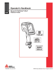
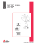
Operator's Handbook Monarch® Printers 9844™ 9854™ TC9854OH Rev. AB 4/08 ©2007 by Avery Dennison Corp. All rights reserved. Copyright © 1997-2008 by Avery Dennison. All rights reserved. Monarch®, 9844, and 9854 are trademarks of Paxar Americas, Inc. Avery Dennison® is a trademark of Avery Dennison Corp. Reprinting and reproduction of these documents, including extracts, is only allowed with the express permission of the manufacturer. More detailed information is available from your supplier. Copyright The documentation is subject to copyright. The copyright claims include all forms and types of material and information which may be protected by current copyright laws. No part of the documentation may be copied, reproduced in any other manner, processed or translated into another language, irrespective of the manner and fashion or with which means this takes place. Copy Electronically stored device information (CD-ROM, Internet) supplied by the manufacturer may be printed out by the user, provided that the print medium serves the use or servicing of the described product. Protected rights Names are generally given without any mention of existing patents, registered designs or trademarks. The absence of a corresponding remark does not give any implication that the name can be used at will. All trademarks are recognised. Alterations No liability is assumed for the accuracy of the contents of this documentation. The manufacturer reserves the right to alter technical or other specifications with no prior notice. Deviations in the documentation from prevailing conditions do not represent an obligation to redeliver. Guarantee The manufacturer does not guarantee the existence or non-existence of properties with the description of subject contents. Nor does the manufacturer give any express or tacit guarantee declarations whatsoever. 05/08 Rev. AB OPERATOR’S HANDBOOK Safety Safety Information General notes on safety are found in this section. Special safety notes and warnings about possibly dangerous operations are listed at the top in the user manual. ¯ Warning notes and warning symbols are also attached directly to the printer and components. Pay attention to these safety notes as well. Warnings in the text Important information that must be followed is marked as follows: WARNING! Indicates risks that could result in death or serious personal injury! « Follow these safety instructions. CAUTION! Indicates risks that could lead to material damage or bodily injury (minor injuries). « The instructions must be followed to prevent damage or injury. 05/08 Rev. AB OPERATOR’S HANDBOOK Safety General safety notes CAUTION! - The printer operates safely when you observe all necessary information. « Proper operation of the product requires the user to read and follow these operating instructions. The warranty does not cover service required as a result of operator error and/or failure to read and follow the documentation. WARNING! - Any changes or modifications not expressly approved by us could void the user's authority to operate the equipment. « Only operate the printer using the system voltage indicated on the nameplate! « Only connect the printer to a grounded power outlet. « Only use the printer within specified environmental conditions! « Only operate the printer when the cover is closed! « Only trained and authorized personnel should operate the printer! « During operation, the printhead can become hot! Be careful when touching the printhead! « Do not make any modifications to the printer! « Do not spill any liquids into the printer! « Repairs to the device must be performed by authorized specialists! « Before cleaning the printer, turn off the printer and disconnect the power supply! « Only use original accessories! « Connect the printer only to other devices that fulfil SELV (safety extra-low voltage) circuit requirements to EN 60950! Keep long hair, loose jewelry, long sleeves, etc. away from the printer during operation. « Wear sufficient personal protection gear. The printer can only be disconnected completely by removing the power supply cable. For this reason: « Make sure that the printer’s power supply socket is readily accessible! « In case of emergency, turn off the printer and disconnect the power supply cable! « Keep these operating instructions in a safe place and make sure they are read. « The printer must be operated, adjusted and serviced by instructed and authorized personnel. « Carefully follow all procedures listed in this manual. Service Special servicing, error searching and error correction are to be performed by authorized personnel. 05/08 Rev. AB OPERATOR’S HANDBOOK Safety Equipment safety Thermotransfer label printers are designed for printing label material, using the thermal direct or thermal transfer printing process. It is possible to use a wide range of label materials and thermal transfer ribbons. See “Specifications” for more information. Avery Dennison assumes no liability for damage due to improper use of the printer and/or material. Protect against injuries that can result from electrical current WARNING! The printer is connected to a power supply! Contact with live electrical components can result in life-threatening currents through the body and burns. « Only use the printer with the cover closed. « Do not remove the cover. « If liquids penetrate the printer, immediately turn off the printer and disconnect the power supply. Protect against injuries that can result from mechanical actions WARNING! Risk of injury during operation due to moving or rapidly rotating parts! Keep long hair, loose jewelry, long sleeves, etc. away from the printer during operation. « Wear sufficient personal protection gear. « Turn off the printer before making any mechanical adjustments. 05/08 Rev. AB OPERATOR’S HANDBOOK Safety Disposal Procedures Waste Electrical and Electronic Equipment (WEEE) for European Union (EU) customers Avery Dennison is fully committed to achieving the EU mandated WEEE directives. W E E E S ym b o l This product, its components, and accessories must be sent to a designated collection facility for proper disassembly and disposal in accordance with the WEEE directives. Any product or accessory marked with the WEEE symbol must be returned to a designated collection facility. For proper disposal of the printer outside the U.S., send the printer and its accessories to: Paxar EMEA, 4 Awberry Court Croxley Business Park, Hatters Lane Watford WD18 8PD U.S. Battery Disposal Information Do not throw in trash. Dispose to your local regulations. Batteries can also be returned postage-paid to: ERC 200 Monarch Lane Door #39 Miamisburg, OH 45342 05/08 Rev. AB OPERATOR’S HANDBOOK Safety FCC Regulations - Class B WARNING This equipment has been tested and found to comply with the limits for a Class B digital device, pursuant to Part 15 of the FCC Rules. These limits are designed to provide reasonable protection against harmful interference when the equipment is operated in a commercial environment. This equipment generates, uses, and can radiate radio frequency energy and, if not installed and used in accordance with the instruction manual, may cause harmful interference to local radio communications. Operation of this equipment in a residential area is likely to cause harmful interference, in which case the user will be required to correct the interference at his own expense. CANADIAN D.O.C. WARNING This digital apparatus does not exceed the Class B limits for radio noise emissions from digital apparatus set out in the Radio Interference Regulations of the Canadian Department of Communications. Le présent appareil numérique n'émet pas de bruits radioélectriques dépassant les limites applicables aux appareils numériques de la classe B prescrites dans le Réglement sur le brouillage radioélectrique édicte par le ministère des Communications du Canada. 05/08 Rev. AB OPERATOR’S HANDBOOK Table of Contents Table of Contents GETTING STARTED ......................................................................................................1-1 Installing the Printer............................................................................................................1-2 Unpacking the printer .........................................................................................................1-2 Carrying the Printer.............................................................................................................1-2 Printer Contents ..................................................................................................................1-3 Removing the Transportation Lock ....................................................................................1-3 Terms to Know ...................................................................................................................1-4 About the Printer.................................................................................................................1-5 About the 9854 Dispenser (Peel) and Internal Liner Takeup .............................................1-7 Identifying Printer Connections ..........................................................................................1-8 Safety Information ..............................................................................................................1-9 Using the Control Panel (Display) ....................................................................................1-10 Operating Modes...............................................................................................................1-11 Using the Printer ...............................................................................................................1-13 Connecting the Printer ......................................................................................................1-13 Setting the Interface ..........................................................................................................1-14 Using the 9854 Printer with Internal Liner Takeup ..........................................................1-14 Using the 9854 Printer with Dispenser .............................................................................1-15 Offline Operation ..............................................................................................................1-16 Online Operation...............................................................................................................1-17 Creating a Print job ...........................................................................................................1-18 Sending a Print Job ...........................................................................................................1-18 Using Compact Flash Cards..............................................................................................1-19 Setting the Realtime Clock (9854 only)............................................................................1-20 SETUP................................................................................................................................2-1 Loading Diagrams...............................................................................................................2-2 Selecting Ribbon/Material ..................................................................................................2-5 Loading Material.................................................................................................................2-6 Loading a Ribbon..............................................................................................................2-11 Material/Ribbon End.........................................................................................................2-13 Setting Printhead Support .................................................................................................2-14 Setting the Material Parameters ........................................................................................2-15 CARE & MAINTENANCE .............................................................................................3-1 Safety ..................................................................................................................................3-2 Troubleshooting ..................................................................................................................3-2 Note on Cleaning ................................................................................................................3-2 Cleaning the Printhead ........................................................................................................3-3 Replacing the Printhead ......................................................................................................3-4 Cleaning the Print Roller ....................................................................................................3-5 Cleaning the Punch (Die Cut) Sensor .................................................................................3-6 SPECIFICATIONS..........................................................................................................A-1 Printers ...............................................................................................................................A-2 Supplies (Material).............................................................................................................A-3 Ribbon (Foil)......................................................................................................................A-3 05/08 Rev. AB OPERATOR’S HANDBOOK 9844/9854 Getting Started Installing the Printer About the Printer Using the Printer 1-1 05/08 Rev. AB OPERATOR’S HANDBOOK Getting Started 9844/9854 Installing the Printer Information in this document supercedes information in previous versions. Check our Web site (www.monarch.com) for the latest documentation and release information. Unpacking the printer Keep the box and packaging materials in case the printer ever needs repair. 1. Remove all loose objects from the packaging. 2. Carefully lift the printer and packaging out of the box. ¯ CAUTION! - Do not lift the printer by holding the plastic parts on the front and back! This could damage the printer. ¯ CAUTION! - Do not grip the front cover to carry the printer! This could damage the printer. Fig. 1: 9854 in the original packaging. 3. Remove the packaging and plastic wrap from the printer. 4. Place the printer on an even surface. Carrying the Printer The printer weighs 31 lbs (14 kg). « To carry the printer, grip the baseplate from the front and back (see Fig. 2). Fig. 2: Packaging When lifting the printer, grip under the baseplate! ¯ Always use the original packaging to move the printer. 1-2 05/08 Rev. AB OPERATOR’S HANDBOOK Getting Started 9844/9854 Printer Contents After you unpack your printer, make sure you have all the necessary components and that the printer was not damaged during shipping. • • Printer Power supply cable The plug for the power supply is different depending on the country of delivery. 9854 with Internal Liner Takeup Reel • Data cable Centronics IEEE 1284 CA Cable 2 m. • Core adapters There are two core adapters each for the material rolls with a internal core diameter of 3 inches (76mm) and 4 inches (101 mm). The core adapters are placed on the printer material dispenser. • Empty foil core For rewinding the ribbon (foil). The backing paper is placed on foil rewind reel. • • Operator’s Handbook Size 10 Torx screwdriver Used to replace the print roller and add a dispensing (peel) edge. • • 9854 printer with installed deflector Housing front part, bottom side with screw (Fig. 3 right side) ¯ Use the housing parts if the printer does not have the internal liner takeup reel (rewinder). Fig. 3: These housing parts are shipped loose with the printer with internal liner takeup. Removing the Transportation Lock 1. Open the cover. 2. Remove the two foam pads holding the printhead in place. 9854 with Dispenser « Remove the connector from its transport position at the printer bottom and connect it to the front of the printer. 1-3 05/08 Rev. AB OPERATOR’S HANDBOOK Getting Started 9844/9854 Terms to Know Review these terms before you continue. Dispenser Peel mode. The printer separates the backing paper from the label as it prints. The printer stops after each label to allow you to remove it. Material Supply (labels, tags, etc.) Self-adhesive material Labels Light barrier Material (supply) sensor Transmission sensor Die cut sensor Reflex sensor Black mark/aperture sensor Punched material Die cut supply. Reflex mark material Black mark or aperture supply. Rewinder Internal liner takeup reel. Winds the backing paper up as it is separated from the labels in dispense (peel) mode. External rewinder Optional device that rewinds printed labels or backing paper after they exit the printer. Endless print quantity Continuous mode. The printer prints labels without stopping. Foil Ribbon 1-4 05/08 Rev. AB OPERATOR’S HANDBOOK Getting Started 9844/9854 About the Printer Cover Open to insert material and foil (ribbon). Control panel LCD graphics display, 4 buttons; displays printer operating status, enables parameter menu settings. Window Allows material/foil check without opening the cover. Connection for additional devices Connection for optional cutter. Fig. 4: Exterior view of the printer. Material rewinder Labelling material roller inserted here. Foil unwinding reel Holds the new foil roll. Foil takeup roll reel Holds the used foil. Material tension roller Ensures even feed of the labelling material. Flange mount for additional devices Optional cutter may be connected here. Guide plate Prevents the material roll from slipping sideways. Pressure lever Opening the pressure lever raises the printhead. Open when loading the material or foil or to clean the printhead or printing roller. Fig. 5: Operating parts. Adapter rings To set the core to the material roll’s diameter. 1-5 05/08 Rev. AB OPERATOR’S HANDBOOK Getting Started 9844/9854 9854 with Dispenser (Peel) and Liner Takeup Dispensing edge Removes the labels from the backing paper. Connector Connection of the dispensing edge sensor. Dispensing roller Holds the material tight over the dispensing edge. Dispensing roller release button Press the button to release the dispensing roller. Fig. 6: Takeup Reel Wraps up the backing paper. Additional operating parts of the printer with dispenser. Deflector Deflects the printed label without dispensing any labels. Fig. 7: Deflector Deflects the backing paper. Takeup Reel Wraps up the Deflector Deflects the labels. labels. Additional operating parts of the printer with internal liner takeup. 1-6 05/08 Rev. AB OPERATOR’S HANDBOOK Getting Started 9844/9854 About the 9854 Dispenser (Peel) and Internal Liner Takeup The 9854 printer has an internal liner takeup reel, which allows labels to be dispensed (using the dispensing edge) or rewound inside the printer (using the deflector) after printing. After the printer is turned on, the takeup reel is initialized and the label material is stretched. If an error occurs, the takeup reel turns off automatically. When the maximum diameter of the takeup roll is reached, a message appears and the takeup reel turns off automatically. The following modes of operation are available with the dispenser: • Dispenser Mode with Dispensing Edge Sensor: The printed label sticks to the dispensing edge (set dispensing position). Once the label is removed, the next label prints. • Dispenser Mode with Foot Switch: Pressing the foot switch triggers the printing and dispensing of one label. The next unprinted label is immediately positioned under the printhead. P See “Using the Dispenser” for more information. 1-7 05/08 Rev. AB OPERATOR’S HANDBOOK Getting Started 9844/9854 Identifying Printer Connections ¯ CAUTION! - Only use approved add-on devices or damage to the printer may occur. « Only connect devices that fulfill SELV (Safety Extra-Low Voltage) circuit requirements to EN 60950. « Connect only original accessories. P Refer to the “Advanced Applications” section on your CD-ROM for more information about the 9854 network connection. Start/stop signal input Connection for a foot switch (signal starts the printer) or a stacker (signal stops the printer). Serial Interface RS232 or RS422/485, on the optional I/O board. Signal interface 4 inputs / 3 outputs, belongs to the optional I/O board. Keyboard connection In offline mode, the keyboard can be used for data input and print job selection. Centronics connection For parallel data transfer. USB connection For USB data transfer. Card insert (9854 only) For Compact Flash cards, which can be used to save fonts, logos or graphics. RS232 interface For serial data transfer. Status LED/Ethernet (9854 only) Network connection (9854 only) Connection for an Ethernet 10/ 100 BaseT network. Power switch Turns printer on/off. Fig. 8: Back view of the 9854 printer. Power supply Connection to the power supply using the supply cable provided. 1-8 05/08 Rev. AB OPERATOR’S HANDBOOK Getting Started 9844/9854 Safety Information ! WARNING Keep hands clear of rollers. A5346 Fig. 9: Warning signs of the printer. The warning sign shown in Fig. 9 explains the risk of getting hands, fingers, loose clothing, jewelry, etc. caught between rotating parts of the printer. The warning sign shown in Fig. 9 warns of the risk of getting hands or fingers burned at hot surfaces close to the printhead. Plug the power supply into a grounded electrical outlet. 1-9 05/08 Rev. AB OPERATOR’S HANDBOOK Getting Started 9844/9854 Using the Control Panel (Display) Display Cut button Online button Feed button Prog button Fig. 10: Control panel Display With 32 digits and two lines, the display shows the operating conditions (modes) for parameters, values, status and errors. You can select the display language. Backlighting ensures good legibility. Button Functions The buttons offer a multitude of operating functions. A logical menu structure is used for operation. The meaning of each button varies according to the operating mode and the menu item. Additionally, special functions have been programmed for certain button combinations. Online Button Cut Button Feed Button Prog Button • • • • • • • • • • • • Switches between online and offline mode. Confirms entries, menu items, and messages. Selects print jobs and enters values in standalone mode. Triggers a cut. Requirements: – Cutter installed and enabled – Printer offline Scrolls down through the menu and selects menu items Decreases values Feeds material when the printer is offline Starts the printing process once feed has been stopped (in online mode) Scrolls up through the menu and selects menu items Increases values Accesses the parameters menu when offline Returns to the previous menu item and/or exits the menu. P For more detailed descriptions of the button functions, see – “Offline Mode” and “Online Mode” in this manual – or refer to the “Info-Printouts and Parameters” section on your CD-ROM. 1-10 05/08 Rev. AB OPERATOR’S HANDBOOK Getting Started 9844/9854 Operating Modes Offline Mode Display OFFLINE Meaning 0 JOBS No jobs are waiting to be processed. Tab. 1:Display in offline mode. Settings can be made when the printer is offline. The offline mode is normally active when the printer is turned on. Print jobs are received with the selected interface, but not processed. ¯ To configure the printer so it goes online when turned on, set the following parameter to Online: SYSTEM PARAMETER > Turn-on mode Online Mode In online mode, print jobs are received and processed immediately. Display Meaning ONLINE 0 JOBS No jobs are waiting to be processed. ONLINE 0. JOBS Current data transfer to the printer is shown on the display by the dot on the bottom right, next to the number of loaded jobs. ONLINE 13 JOBS During printing, the display also shows the Restcount: 25 number of print jobs read (13) and the remaining number of labels (25) to be printed in the current job. ONLINE 13 JOBS If a print job recognizes an endless (continuous) Restcount: endless number of labels to be printed, then the remaining number for this job is also shown as endless. Tab. 2: Possible messages in online mode. ¯ To stop printing, press Online. Message Mode The printer uses the message mode to signal an error or a particular operating status. Message mode indicates that the printer is waiting to quit or for a fault to be corrected. When exiting, the printer switches from message mode to offline mode (depending on the error and the progress of the previous process). Display Meaning Status 5001 No punch detected Messages are made up of the status number and a brief descriptive text. Tab. 3: Example of a message. The messages shown in Table 3 occur when the printer is set for using labelling material with perforation, but continuous form material without perforation is loaded. The printer continues to feed the material for a few seconds before it generates an error message. P Refer to the “Error Messages” section on your CD-ROM for more information on message reports and a detailed list of all messages. 1-11 05/08 Rev. AB OPERATOR’S HANDBOOK Getting Started 9844/9854 Standalone Mode (9854 only) In standalone mode, the print jobs are not transferred with a data cable, but are stored on a Compact Flash card. They are selected from the printer’s display or a keyboard connected to the printer. P Refer to the “Advanced Applications” section on your CD-ROM for more information on using standalone mode for the 9854 printer. 1-12 05/08 Rev. AB OPERATOR’S HANDBOOK Getting Started 9844/9854 Using the Printer Connecting the Printer WARNING! Touching live electrical parts causes exposure to hazardous electrical currents that may lead to burns! « Make sure the printer is turned off before connecting the power cable. « Only connect the printer to an electrical outlet that provides the correct voltage, which can be found on the rating plate. « Only connect the printer to a grounded electrical outlet fitted to authorized standards. « Connect the power cable so that: – no one trips or steps on it. – it can be easily unplugged from the power outlet. 1. Turn off the printer. On the back of the printer press (O) to turn off the printer. 2. Connect the printer to the power supply using the cable provided. 3. Using the data cable supplied, connect the Centronics interface on the printer to the host computer. 4. Turn on the printer. On the back of the printer, press (I) to turn on the printer. Display Description System start... The boot loader has started. System start... Start user prog Valid firmware recognized, program starts. Avery V 1.02 Printer type (for example: AP 5.4/9854) Version number of the printer firmware. AP 5.4 Memory: 8MB Flashcard: 32MB Internal RAM (for example: 8 MB) Optional RAM on the Compact Flash card (for example: 32 MB) – only displayed when a Compact Flash card is in use. OFFLINE 0 JOBS Offline mode Tab. 4: Messages on the display when the printer is turned on. 5. Press Online to switch to the online mode: ONLINE 0 JOBS ¯ When the parameter SYSTEM PARAMETER > Turn-on mode is set to Online, the printer switches to online mode when turned on. 1-13 05/08 Rev. AB OPERATOR’S HANDBOOK Getting Started 9844/9854 Setting the Interface By factory default, the printer is set for data transfer using the Centronics interface. Print data can be transferred using the RS232, USB or Ethernet interface (9854 only). « Select the interface with the following parameter: Set INTERF. PARAM. > EASYPLUGINTERPR to Interface P Refer to the “Info-Printouts and Parameters” section on your CD-ROM for more information about setting parameters. P Refer to the “Advanced Applications” section of your CD-ROM for more information about using 9854 Ethernet. Using the 9854 Printer with Internal Liner Takeup Disable « Set SYSTEM PARAMETER > Periph. Device to None ¯ If you do not insert printing material before enabling the liner takeup, an error message appears. P For more information on loading material, see “Loading Material.” Enable 1. Set SYSTEM PARAMETER > Periph. Device to Intern Rewinder When enabled, the rotational direction of the takeup is set. Rewinder direct. Facing outside Facing outside is the default setting. 2. Press Cut/Feed to change the rotation direction. 3. Press Enter to confirm your setting. The printer restarts. The main menu now contains the additional menu REWINDER PARA, which holds the parameter Rewind direction. This can be used to change the rotational direction. During initialization, the printer attempts to stretch the label material. Possible Errors Shortly after enabling the internal liner takeup, you may see Status 5004 Rewinder mat. tear 1-14 05/08 Rev. AB OPERATOR’S HANDBOOK Getting Started 9844/9854 Possible causes: – Material is not loaded, or the material’s end was not fixed to the takeup reel. Attach the end to the takeup reel and press Online. – The material is not stretched tightly. Press Online. The printer is now ready for the next print job. You may need to adjust the basic initialization settings because of: • • • • • Very small labels Very rough backing paper Backing paper much heavier than label Labels stuck to backing paper Backing paper perforated along label contour Using the 9854 Printer with Dispenser Disable « Set SYSTEM PARAMETER > Periph. Device to None Enable « Set SYSTEM PARAMETER > Periph. Device to Dispenser The printer restarts. The main menu now contains the additional menu DISPENSER PARA , which holds the parameters required for dispenser mode: Parameter Possible Settings Dispenser Mode Real 1:1 mode (default), batch mode, Normal 1:1 mode Dispensing Position Set in millimeters (default: 0.0 mm) Display Mode Job rest quant. (default), Dispense counter Dispense counter Preset Amount (default: 0) Application Mode Safe mode (default), Immediate mode Start Mode Edge (default), Level low active Start Source Foot switch (default), Light barrier Tab. 5: Parameters in the menu DISPENSER PARA. P Refer to the “Info-Printouts and Parameters” section of your CD-ROM for more information on the listed parameters. 1-15 05/08 Rev. AB OPERATOR’S HANDBOOK Getting Started 9844/9854 Configuring the Dispenser Position • Application A: The label is dispensed (peeled) so that a small portion still sticks to the backing paper above the dispensing edge. After the dispensed label is removed, the next label is immediately printed and dispensed. « Set DISPENSER PARA > Dispenseposition to –6.0 mm (set to –8.0 mm if the material is very adhesive). « Set DISPENSER PARA > Start Source to Light barrier. • Application B: The printing and dispensing of the label is controlled by the optional foot switch. « Set SYSTEM PARAMETER > External Signal to Stacker full. « Set DISPENSER PARA > Dispenseposition to –6.0 mm (set to –8.0 mm if the material is very adhesive). « Set DISPENSER PARA > Start Source to Foot switch. ¯ If using very short labels (< 40 mm) set PRINT PARAMETERS > Material length Label length < 40 mm < 40 mm (1.6 inches). The printer automatically initializes the material, which improves the impression accuracy of the printout. P Refer to the “Info-Printouts and Parameters” section on your CD-ROM for more information on parameter DISPENSER PARA > Calibration mode. Offline Operation Press the buttons indicated in black to perform the listed functions. • Switching from offline mode to online mode: OFFLINE • x JOBS x JOBS xx Online ONLINE Stopped x JOBS xx x JOBS Online Feed OFFLINE feeding… x JOBS OFFLINE feeding… x JOBS OFFLINE x JOBS Material travels backwards under the printhead: OFFLINE • ONLINE Slow material and ribbon feed: OFFLINE • Online Switch to online mode when the print job is stopped: OFFLINE Stopped • x JOBS x JOBS Cut Online x JOBS Cut Online Feed Reset: OFFLINE 1-16 05/08 Rev. AB OPERATOR’S HANDBOOK Getting Started 9844/9854 • Access the parameter menu: OFFLINE • Prog PRINT INFO Feed material until the next punch (die cut) is reached or when the button is held down: OFFLINE • x JOBS x JOBS OFFLINE feeding… Feed x JOBS Setting the label length automatically: OFFLINE x JOBS Feed Prog OFFLINE x JOBS Manual Calibrate After pressing the two buttons, the printer feeds the label material, until two punches have passed the label sensor. The measured label length is displayed and saved into parameter PRINT PARAMETERS > Material length. Next, the parameter PRINT PARAMETERS > Material type is set to “punched.” OFFLINE x JOBS Displays the measured label length. 198.5 mm ¯ The label length measured by this function is from label end to label end. If material with very large punches is used, this measurement does not work properly. In this case, measure and set the label length manually (label length + punch length). Online Operation Press the buttons indicated in black to perform the listed functions. • Switching to offline mode: ONLINE • x JOBS Prog x JOBS Print contrast xxx% Interrupting the print job: The printer finishes printing the current label. ONLINE X JOBS Restcount XXX a) The message “Stopped • OFFLINE Online Setting the print contrast: Press Feed to increase and Cut to decrease the print contrast. ONLINE • x JOBS Prog ONLINE Stopped X JOBS XXX a xxx” alternates with “Press Feed.” Switching to offline mode while the print job is stopped: ONLINE Stopped X JOBS XXX Online OFFLINE x JOBS 1-17 05/08 Rev. AB OPERATOR’S HANDBOOK Getting Started 9844/9854 • • Continuing the print job: ONLINE X JOBS Stopped XXX ONLINE X JOBS Restcount XXX Feed Standalone operation (9854 only): Selecting a print job stored on a Compact Flash card (for example, Testdat.FOR): ONLINE x JOBS Online Prog Choose a file Testdat.FOR Creating a Print job There are two ways to create a print job: Use the Microsoft® Windows printer driver, or create a text file using print commands. Windows Printer Driver • Printer drivers are available for different versions of Windows. You can print from nearly every Windows application using the printer drivers. However, functionality is strongly dependent on the choice of software. We recommend label layout programs. « Printer drivers for different versions of Windows are available on our Web site (http://www.machines.averydennison.com/printersystems_gb.nsf/ wview/L4L3?OpenDocument). Select the drivers for models AP4.4 (9844) and AP5.4 (9854). P See the printer driver’s help function for more information. Refer to your Windows operating system help to install a driver. File with Print Commands • You can write a sequence of commands in a text file and send it to the printer. To do this, you can use any text editor and the MS-DOS copy command. Easy Plug provides a special command language to program print jobs. However, writing a print job in text file format requires some programming knowledge. You cannot preview the resulting printout on the screen. Print a test print to see a copy of the finished result. P Refer to the Easy Plug manual for examples of print jobs. Sending a Print Job The printer processes print jobs once the jobs are sent to the printer’s RAM either by direct transfer from your computer with a data cable, or by saving to a Compact Flash (CF) card for the 9854 printer. Data Cable The print job can be sent using parallel or serial communication. Connect the computer and the printer with the serial or parallel cable. Send the print job file – from the DOS window – to the interface (for example, “copy testjob.txt lpt1” to send the print job to the parallel interface). To send the print job from a text program, make sure the printer driver is installed. 1-18 05/08 Rev. AB OPERATOR’S HANDBOOK Getting Started 9844/9854 Compact Flash Card You need the following to load a print job from a Compact Flash card: • • • • a 9854 printer a Compact Flash card (copy the print job to the \FORMATS directory) a computer with a PCMCIA drive and an adapter for the Compact Flash card. Rename the print job file on the Compact Flash card to autostrt.for so the printer recognizes it. Once this is finished, the printer completes the print job as soon as it is set to online mode. Using Compact Flash Cards ¯ CAUTION! - Only use approved Compact Flash cards (order number 160002). ¯ CAUTION! - Wait five seconds after turning off the printer before removing or inserting the Compact Flash card! ¯ The printer firmware cannot use more than 128 MB of card storage capacity. Slim guide notch Wide guide notch Fig. 11: Example of a 32MB Compact Flash card. Inserting a CF card 1. Turn off the printer. Wait five seconds. 2. Insert the Compact Flash card completely into the card slot. The wide guide notch should face upwards (see Fig. 12). ¯ Push the Compact Flash card into the slot until the release button (1) comes out. The card sits flush with the back wall. Fig. 12: Inserting a Compact Flash card into a 9854 printer. If the Compact Flash card is inserted correctly, it sits flush with the printer’s back wall (right). 1-19 05/08 Rev. AB OPERATOR’S HANDBOOK Getting Started 9844/9854 Setting the Realtime Clock (9854 only) The 9854 printer’s realtime clock can be used to calculate and print the expiration date of perishable goods. To set the realtime clock: 1. Navigate to the parameter SYSTEM PARAMETERS > Realtime clock Realtime clock dd.mm.yyyy hh:mm dd=day, mm=month, yyyy=year, hh=hour, mm=minute 2. To enter the date and time, press Cut to shift the cursor, Feed to change the setting, and Online to save it. P Refer to the “Info Printouts and Parameters” section on your CD-ROM for more information on setting parameters. Outputting the realtime clock value using Easy Plug Use the following Easy Plug commands to output the current realtime clock value: • • • #YC realtime as text #YS realtime as bar code #VDD defining date and time variables P Refer to the Easy Plug manual for more information. 1-20 05/08 Rev. AB OPERATOR’S HANDBOOK 9844/9854 Setup Loading Diagrams Printer with Dispenser (Peel) Selecting Ribbon/Material Loading Material Loading a Ribbon Material/Ribbon End Setting Printhead Support Setup 2-1 05/08 Rev. AB OPERATOR’S HANDBOOK Setup 9844/9854 Loading Diagrams The loading diagrams show the material and ribbon path through the printer. Material is wound with the labels facing outwards Ribbon is wound with the colored side facing inwards. 1 2 3 11 10 4 9 601 5 2 4 3 5 8 Bild_3/Z0194.cdr • • 7 Fig. 1: 6 Material and ribbon path in printer. No. Description 1 Ribbon rewinding reel 2 Ribbon unwinding reel 3 Material tension roller 4 Guide disk 5 Material roll 6 Material guide 7 Light barrier fitting 8 Print roller 9 Adjusting wheel for printhead support 10 Pressure lever 11 Ribbon deflection roller Tab. 1:Operating parts of the printer. 2-2 05/08 Rev. AB OPERATOR’S HANDBOOK Setup 9844/9854 9854 Printer with Internal Liner Takeup Reel (Rewinder) 1 2 3 15 14 4 13 5 601 5 2 4 3 Bild_3/Z0194.cdr 12 11 Fig. 2: 10 9 8 7 6 Material and ribbon path through printer with internal liner takeup. No. Description 1 Ribbon rewinding reel 2 Ribbon unwinding reel 3 Material tension roller 4 Guide disk 5 Material roll 6 Clip 7 Internal liner takeup reel 8 Deflection roller 9 Material guide 10 Light barrier fitting 11 Deflection plate 12 Print roller 13 Adjusting wheel for printhead support 14 Pressure lever 15 Ribbon deflection roller Tab. 2: Operating parts of the printer with internal liner takeup. 2-3 05/08 Rev. AB OPERATOR’S HANDBOOK Setup 9844/9854 9854 Printer with Dispenser (Peel) 1 2 3 15 14 4 13 5 601 5 2 4 3 12 Bild_3/Z0194.cdr 11 10 Fig. 3: 9 8 7 6 Material and ribbon path through printer with dispenser (peel). No. Description 1 Ribbon rewinding reel 2 Ribbon unwinding reel 3 Material tension roller 4 Guide disk 5 Material roll 6 Clip 7 Internal liner takeup reel 8 Deflection roller 9 Material guide 10 Light barrier fitting 11 Deflection plate 12 Dispensing edge (peel) 13 Adjusting wheel for printhead support 14 Pressure lever 15 Ribbon deflection roller Tab. 3: Operating parts of the printer with dispenser (peel). 2-4 05/08 Rev. AB OPERATOR’S HANDBOOK Setup 9844/9854 Selecting Ribbon/Material About Material Use Monarch-approved material. See “Specifications” for more information. About Ribbons Use Monarch-approved ribbon. See “Specifications” for more information. 2-5 05/08 Rev. AB OPERATOR’S HANDBOOK Setup 9844/9854 Loading Material WARNING! Rotating axles! – Keep long hair, loose clothing, jewelry, etc. away from the printer! « Do not operate the printer with the cover open! « Be careful when touching the printhead. It may be hot. The printer can use both roll and fan-fold material. Follow these steps to load material. P See “Specifications” for more information about the media. 1. Open the cover. 1 2. Release the printhead pressure lever (1). 3. Remove the external guide plate (2) from the material roller. 4. Push the material roll onto the correctly sized adapter disc (3) on the unwinder. Push the guide plate back on. ¯ The material roll turns counterclockwise when unwinding! ¯ ¯ 5. Insert the material as shown (Fig. 2). 2 ¯ Be sure to thread the material around the material tension roller (4) as well! 2-6 05/08 Rev. AB OPERATOR’S HANDBOOK Setup 9844/9854 6. Push the material guide (5) up to the edge of the material, without pinching the material (Fig. 3). 3 7. Slide the light barrier fitting using the grip (6) until the pointer (7) is located above the material perforations (Fig. 4). 4 ¯ The optional reflex sensor is located 5mm to the right of the pointer below the material! 8. Thermodirect printing: Close the pressure lever. Thermotransfer printing: See “Loading Ribbon” to continue. 2-7 05/08 Rev. AB OPERATOR’S HANDBOOK Setup 9844/9854 Loading Fan-fold Material Follow these steps to load fan-fold material: 1. Open the cover. 2. Release the printhead pressure lever (1). 3. Position the fan-folded material behind the printer (Fig. 1). 1 4. Guide the material over the material unwinder. Push the material guide up to the edge of the material without pinching the material. 5. Slide the light barrier fitting using the grip (6) until the pointer (7) is located above the material perforations (Fig. 2). 2 ¯ The optional reflex sensor is located 5mm to the right of the pointer below the material! 6. Thermodirect printing: Close the pressure lever. Thermotransfer printing: See “Loading Ribbon” to continue. 2-8 05/08 Rev. AB OPERATOR’S HANDBOOK Setup 9844/9854 Loading the 9854 with the Internal Liner Takeup Reel 1. Follow the steps for loading material from the previous section. Then, follow these steps. 2. Thread the end of the material to the internal liner takeup reel (1) as shown and secure it with the clip (2) (Fig. 1). 3. Choose the rotation direction of the takeup reel (face inside or outside): Select parameter REWINDER PARA > Rewind direction. After turning on the printer, the takeup reel rotates slowly until the material is pulled tight. You may see Status 5004 Rewinder mat. tear before the material is pulled tight. « If this happens, press Online to clear the message. You may have to press it several times. 1 2-9 05/08 Rev. AB OPERATOR’S HANDBOOK Setup 9844/9854 Dispensing (Peel) 9854 only 1. Follow the steps for loading material from the previous section. Then, follow these steps. 1 2. Remove the labels from the first 10 inches (25 mm) of backing paper (Fig. 1). 3. Press the red button (1) at the dispensing edge to release the peel roller (Fig. 1). 4. Remove the peel roller, feed the label web through as illustrated (Fig. 1) and press the roller back between its bearings. 5. Thread the backing paper backwards to the takeup reel (2) as shown (fig. 2). 2 6. Wrap the end of the backing paper clockwise around the takeup reel (2) and secure it with the clip (3). 7. Turn the takeup reel counter-clockwise until the backing paper is pulled tight. After turning on the printer, the reel rotates slowly until the material web is pulled tight (Fig. 3). You may see Status 5004 Rewinder mat. tear before the material is pulled tight. « If this happens, press Online to clear the message. You may need to press it several times. 3 2-10 05/08 Rev. AB OPERATOR’S HANDBOOK 9844/9854 Loading a Ribbon WARNING! Rotating axles! – Keep long hair, loose clothing, jewelry, etc. away from the printer! « Do not operate the printer with the cover open! « Be careful when touching the printhead. It may be hot. ¯ Ribbon is only needed for the thermotransfer printing. 1. Open the cover. 2. Release the printhead pressure lever (1). 3. Push the ribbon roll onto the ribbon unwind reel (2) as far as it will go. Push an empty ribbon sleeve onto the rewind reel (3). 1 ¯ The ribbon turns counter-clockwise when unwinding. 4. Load the ribbon as shown into the printer (Figs. 1 and 2). Secure the ribbon end to the empty ribbon sleeve. 5. Turn the rewind reel counter-clockwise a few times until the ribbon is crease-free. Replacing a used ribbon 1. Open the printhead pressure lever. 2. Remove the used ribbon roll from the rewind reel. 3. Remove the empty ribbon core from the unwind reel and place it on the rewind reel. 4. Load a new ribbon roll following the steps above. 2 Setup 2-11 05/08 Rev. AB OPERATOR’S HANDBOOK 9844/9854 Quick ribbon exchange 1. Open the pressure lever (Fig. 1). 1 2. Remove both ribbon rolls from the ribbon reels. Remove the ribbon from underneath the printhead (Fig. 2). 2 Load the new ribbon as follows: 1. Push the ribbon, which is between the rolls, under the printhead (Fig. 2). 2. Push both ribbon rolls onto the ribbon reels as shown (Fig. 1). 3 Setup 2-12 05/08 Rev. AB OPERATOR’S HANDBOOK Setup 9844/9854 Material/Ribbon End Material Stock End If the material end has passed the material sensor, you see Status Material end 5002 « Release the pressure lever and pull the end of the remaining material from the front side of the printer. Ribbon End If the ribbon roll is emptied (the ribbon unwind reel is not turning), you see Status Ribbon end 5008 « See “Loading a Ribbon” to continue. ¯ Ribbon end detection can be turned off for theromodirect printing. « To do so, set the parameter SYSTEM PARAMETERS > Ribbon autoecon. to Thermal printing. P Refer to the “Info-Printouts and Parameters” section on your CD-ROM for more information. 2-13 05/08 Rev. AB OPERATOR’S HANDBOOK Setup 9844/9854 Setting Printhead Support When printing narrow labels, the printhead may come into contact with the print roller where there is no material. This can lead to premature wear of the printhead and to different print intensity between the two edges of the label. ¯ When using narrow labels, enable the printhead support. Small = material width < printhead width. Change the printhead support by using the adjusting wheel (1). Position 0 is recommended for wide labels. Fig. 1: The adjusting wheel for the printhead support. 1. For narrow labels, turn the adjusting wheel clockwise until the pointer indicates 1 on the dial. This causes the printhead to be raised at the outside. 2. Print a test print and check for even print quality. If the print quality is still uneven, turn the adjusting wheel a little further. 3. Repeat steps 1 to 3 until the print quality is the same across the entire width of the label. 2-14 05/08 Rev. AB OPERATOR’S HANDBOOK Setup 9844/9854 Setting the Material Parameters Use the following three parameters to set the material properties: Parameter Function PRINT PARAMETERS/ Material type Sets the material type (perforated or endless) PRINT PARAMETERS/ Material length Sets the material length PRINT PARAMETERS/ Material width Sets the material width SYSTEM PARAMETERS/ Sets the sensor type (reflex or transmission) Light sens based on the material (marks or . type perforations) Tab. 1:Important parameters for setting the material properties. P Refer to the “Info-Printouts and Parameters” section on your CD-ROM for more information on setting parameters. 2-15 05/08 Rev. AB OPERATOR’S HANDBOOK 9844/9854 Setup 2-16 05/08 Rev. AB OPERATOR’S HANDBOOK 9844/9854 Care & Maintenance Cleaning the Printhead Cleaning the Print Roller Cleaning the Punch (Die Cut) Sensor 3-1 05/08 Rev. AB OPERATOR’S HANDBOOK Care & Maintenance 9844/9854 Care & Maintenance Regular maintenance is required to make sure the printer is always operating safely. Safety WARNING! Maintenance and cleaning may result in hazardous situations. Accidents can occur if safety instructions are not followed! « Turn off the printer and disconnect the power supply before any cleaning or maintenance work! « Do not spill liquid into the printer! « Do not spray any cleaner directly on the printer! Moisten a cloth with the recommended cleaning agent to clean the printer! Troubleshooting Error Messages When an error occurs, read the messages first and refer to the documentation for more information. Calling Technical Support If you need to call Service, have your printer’s model number and serial number ready. Call Service to order spare parts. Note on Cleaning Frequency of Care Frequent maintenance and cleaning is required to make sure the printer is operating properly. The rate and frequency at which you print determine how often you must clean the printer. ¯ Frequently check the printhead and feed rollers for paper or adhesive buildup. ¯ WARNING! - Do not use any cleaning agent that could damage or destroy the resin surface, labelling, display, nameplates, electrical components, etc. ¯ WARNING! - Do not use any cleaning agents that are abrasive or damaging to plastics. Avoid acid or alkaline solutions. 3-2 05/08 Rev. AB OPERATOR’S HANDBOOK Care & Maintenance 9844/9854 Cleaning the Printhead CAUTION! - The printhead is sensitive to static electricity, which can damage the printhead or reduce its life. Ground yourself by touching a metal surface, such as the printer’s metal base, before cleaning the printhead. « Do not use sharp objects to clean the printhead! You may need to clean the printhead when you see voids or streaks in the printing or notice uneven printing. 1. Turn off the printer. 2. Open the printhead pressure lever. The printhead lifts upwards. 1 3. Remove the material and ribbon. Cleaning with the cleaning pen (order part number 114226): 4. Applying light pressure, go over the printhead (1) a few times with the cleaning pen (Fig. 1). Cleaning with isopropyl alcohol: ¯ Use isopropyl alcohol if you do not have a cleaning pen. « Moisten a cotton swab with isopropyl alcohol and wipe the printhead clean. 3-3 05/08 Rev. AB OPERATOR’S HANDBOOK 9844/9854 Replacing the Printhead 1 Fig. 1: Printhead (1) with bracket (2). CAUTION! - Printhead (1) and bracket (2) were adjusted exactly using special tools. 2 « Do not loosen the screws (3) attaching the printhead to the bracket. Removing the printhead: 1. Turn off the printer and disconnect the power supply. 2. Remove the material and ribbon. 3. Close the pressure lever (1). 4. Remove the two thumb screws (Fig. 1). 5. Open the pressure lever. 3 The printhead is released from the fastener and remains on the print roller (Fig. 2). 6. Remove both printhead cables from the printhead (Fig. 3). Connecting the printhead: Note the resistance of the new printhead listed on the printhead’s label. 1. Connect the printhead cable. 2. Press the printhead against the fastener from below and tighten the thumb screws. 3. Navigate to the parameter SYSTEM PARAMETERS > Head resistance and enter the printhead resistance from the printhead’s label. 4 Care & Maintenance 3-4 05/08 Rev. AB OPERATOR’S HANDBOOK 9844/9854 Cleaning the Print Roller 1 Clean the print roller when you see adhesive buildup or dirt on the roller. 1. Turn off the printer and disconnect the power supply. 2. Remove the material and ribbon. ¯ You can easily access the print roller if you remove the tear-off edge (1) first. 3. Remove the tear-off edge and unfasten the screw (2) in the middle of the tear-off edge with a size 10 Torx screwdriver (Fig. 2). 2 4. Moisten a lint-free cloth with isopropyl alcohol and wipe the print roller (Fig. 3) clean. Turn the roller with your finger to clean all the way around. 5. Replace the tear-off edge. 3 Care & Maintenance 3-5 05/08 Rev. AB OPERATOR’S HANDBOOK Care & Maintenance 9844/9854 Cleaning the Punch (Die Cut) Sensor 1 During printing, the punch sensor can become contaminated with lint and unable to sense material. 1. Remove the cover (1) gently and swivel downwards (Fig. 1). 2. Remove the sensor arm (2) (Fig. 2). 3. Clean the opening (3) with compressed air. ¯ The transmission sensor is located in the upper and the lower part of the sensor arm on a level with the indicator (4). You can find the reflex sensor about 5 mm further below. 2 CAUTION! - The sensor surface is very sensitive to scratches! « Do not use sharp objects or solvents when cleaning the sensors. 3-6 05/08 Rev. AB OPERATOR’S HANDBOOK 9844/9854 Specifications Printers Supplies (Material) Ribbon (Foil) A-1 05/08 Rev. AB OPERATOR’S HANDBOOK Specifications 9844/9854 Specifications Printers Height: 10.7 inches (272 mm) Width: 10.3 inches (260 mm) Depth: 18.2 inches (462 mm) Weight: 31 lb. (14 kg) 35 lb. (16 kg) with dispenser (peel) Operating Limits: 40° to 100°F (4° to 38°C) Storage: 24° to 140°F (-4° to 60°C) Humidity: 30% to 85% non-condensing Printhead: 203 dpi (8 dots per mm) or 300 dpi (12 dots per mm) Printing Method: Thermotransfer (ribbon) or Thermodirect Print Width: 4.2 inches (105 mm) maximum Print Speed: 2 to 8 ips (50 to 200 mms) 2 to 6 ips (50 to 150 mms) with 300 dpi A-2 05/08 Rev. AB OPERATOR’S HANDBOOK Specifications 9844/9854 Supplies (Material) Width: 0.6 to 4.8 inches (15 to 120 mm) 1.2 to 4.3 inches (30 to 110 mm) - 9854 with dispenser Min. Length: 0.2 inches (5 mm) 1.2 inches (30 mm) - 9854 with dispenser Roll Diameter: 8.35 inches (210 mm) maximum outer diameter 4.9 inches (125 mm) - 9854 with liner takeup When selecting a material, note the following items: – The abrasiveness of the printing surface. – The chemical reaction when the ink is transferred. – The temperature required to transfer the ink. Abrasive Material If the material is very abrasive, the printhead wears more quickly than normal. This is important in thermodirect printing. It is not so critical for thermotransfer printing, because the ribbon can be wider than the material, ensuring that the printhead is protected across the entire width of the material. Printhead temperature The same applies if the temperature of the printhead is too high. The material and ribbon take longer to cool down, the print quality is more critical and the printhead wears out more quickly. For paper thicker than 240g, adjust the contact pressure and the position of the printhead. Ribbon (Foil) Width: 9844: 1.0 to 4.4 inches (25 to 110 mm) 9854: 1.0 to 4.5 inches (25 to 114 mm) Length: 500 m (maximum) The ribbon width must be greater than the material width. Since some material is more abrasive to printheads than others, using a ribbon wider than your material helps protect the printhead. Replacement printheads are expensive. A-3 05/08 Rev. AB OPERATOR’S HANDBOOK 9844/9854 Specifications A-4 Visit www.monarch.com for sales, service, supplies, information, and telephone numbers for our locations throughout the world. TOLL FREE: 1-800-543-6650 (In the U.S.A.) 1-800-363-7525 (In Canada)