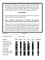
1
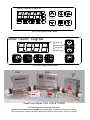
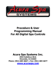
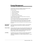
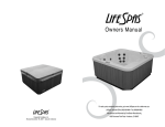
SMARTOUCH DIGITAL
Series
1000 & 2000
USER
&
PROGRAMMING
MANUAL
701 W. Foothill Blvd Azusa CA 91702
(626) 969 - 9655 Fax (626) 334 - 4809
SmarTouch Digital controls are microprocessor based
electronic spa control systems and as such are
susceptible to static discharge and high levels of humidity.
To prevent premature control failure do not hose down,
flood or allow water to enter the control box enclosure.
CAUTION
High voltage levels exist inside the control box, they can
cause injury and even electrocution.
Only certified electricians or trained servicemen
should have access to the components inside the box.
There are no user serviceable parts inside the box. All
programming is done at the spa side control panel without
the need to access the inside of the box. If for some
reason the control system needs to be serviced, please
contact Applied Computer Controls for proper procedures.
Model # _________________ Serial # __________________
Software Rev # _______ Purch Date _____ / _____ /_______
Device
Primary Pump
Circulating Pump
Second Pump
Third Pump
Air Blower
Spa Light
Fiber Optic Light
Fiber Optic Wheel
Spa Mister
120V 240V 1Sp
2Sp
12V
Installed
TABLE OF CONTENTS
INTRODUCTION
IN A HURRY
Setting Temperature
The SET Key
Time Of Day TOD
Setting TOD
THE CONTROL PANEL
DEVICE CONTROL GROUP
Primary Water Pump
Air Blower
Auxiliary Pump(s)
Spa Light
Summary of Device Functions
STATUS CONTROL GROUP
The TEMP key
The TIME key
The SET key
PROGRAMMING THE SC-1000 & SC-2000
Parameter Programming
Programming Example
PROGRAMMING SYSTEM OPTIONS
User Options
Protected Options
Diagnostic Values
ERROR MESSAGES
CoLD, OH, LHoH
SEoP,SESH,PSoC,PSoL,PSoH
ToE - Time out error
ELECTRICAL COONECTION INSTRUCTIONS
bRANCH CIRCUIT BREAKER REQUIREMENTS
Page 3
4
5
5
5
6
6
7
7
7
8
8
8
9
10
10
11
11
12
12
13
17
17
19
20
21
21
22
22
23
24
INTRODUCTION
Thank you for buying a spa equipped with a SmarTouch
Digital control systems. Many years of experience went into
the design of this family of controls. You can be assured your
spa control system is the most advanced, it is highly reliable
and will serve you for many years to come.
The control system has been designed with the you the user
in mind. It is very easy to operate and requires a minimal effort
on your part. You may use it just as it comes to you and
without any programming. Yet you have the option of getting
deeply involved in the inner workings of the control if you so
choose. You can custom tailor it to fit your needs.
Please take the time to read at least the first section (next
page) “IN A HURRY - READ THIS” portion of the manual
before starting to use your spa for the first time. You can
familiarize yourself with the rest of the manual at your leisure.
This manual will also serve as a reference if you choose to
modify the operation of your spa.
SAVE THIS MANUAL.
Make it available for other spa users.
You should also have a spa user’s manual which explains
how to care for your spa. Please read and follow all
instructions in your spa user’s manual. Maintaining the proper
levels of pH and the sanitizer will extend the life of your spa
equipment. Improper chemical levels in the spa are sure to
cause premature heater failure as well as failure of other
components in the system. Failures caused by chemical
imbalance are not covered by warranty.
Page 4
IN A HURRY - READ THIS
For those who don’t like to read manuals or would like to read the
manual later, please read at least the following section.
SmarTouch Digital comes to you with a universal set
of default settings. If you choose to keep these
settings, then you only need to remember 2 things :
how to set the spa temperature and to press the SET
key whenever you are done using the spa.
Setting Temperature
♦ Press and hold the TEMP key for 2 seconds. Release all keys
The display will flash the current selected temperature.
♦ Using the TEMP and TIME keys (UP and DOWN arrows)
scroll to the desired temperature.
♦ Press the SET key to lock in the new selection
The SET Key
After using the spa, press the SET key to tell the microcontroller you
are done using the spa. It will then take over the spa’s management
including the different filtration cycles, heat maintenance, economy
modes and protection against freezing.
Upon entering this mode the FILTER light is turned on and a post use
filtration cycle is executed - that is when the spa needs filtration the
most. The default system setting includes a 3 hour economy mode,
the pump will come on at most once every 3 hours to sample water
temperature and heat if necessary. The controller remembers when
you have used the spa and in anticipation of your next usage will
perform a 3 hour Auto Filtration cycle before your next spa use.
SmarTouch Digital Series 1000 and 2000 is a family of intelligent, spa
control systems. These systems are rich with features and can be
extensively programmed to fit just about any need. The rest of this
manual will explain the function of each of the keys on the control
panel, how to change programmed settings and what each setting
does. It will also explain all the error messages that you may
encounter, and their significance and way to correct them.
Page 5
Time Of Day (TOD)
SmarTouch Digital maintains a 12 hour AM / PM internal real time
clock TOD (Time Of Day). The clock based on the line frequency.
There is no battery backup and whenever the power is turned off,
TOD is no longer correct. It defaults to 12:00 AM whenever the power
is turned on.
Setting TOD is only necessary if you are going to program the filtration
and silence cycles. If you use the factory default settings then you do
not need to set TOD.
If you set TOD then SmarTouch will display time every first 10
seconds of each minute. If TOD has not been set then it will not be
displayed.
Setting TOD
1. Press and hold the TIME key for 2 seconds. Current TOD will
be displayed with the hour portion flashing.
2. Release the TIME key.
3. Using the TEMP and TIME keys scroll up and down to the
desired hour. - Notice the AM / PM Led.
4. When the correct hour and AM / PM are displayed press the
SET key to lock in the new hour.
5. The display will now flash the minutes portion of current TOD.
6. Using TIME and TEMP scroll to the desired minutes.
7. When the correct minutes are displayed press the SET key to
lock in the time of day (hours and minutes)
Note : TOD is the only parameter in SmarTouch Digital that is not
preserved on power down. On power up it will default to 12:00 AM, all
other parameters are restored to the their last setting.
Every time the controller is powered up, the microprocessor
automatically measures and determines whether the line frequency is
50 or 60 cycles in order to maintain the correct TOD.
Page 6
THE CONTROL PANEL
The control panel is normally installed on the lip of the spa for easy
and convenient access. Within the panel housing is a 4 digit LED
display used to communicate to the user spa temperature, TOD,
elapsed user time, programming, status - diagnostic and error codes
and messages. There are 2 different size panels. They are
interchangeable. the 2000 Series panel can have up to 7 keys, the
1000 Series panel will have at most 6 keys. These are membrane type
switches which when depressed generate a signal that the
microprocessor will interpret and act upon. The switches are labeled
and have specific functions. They are divided into 2 groups:
Device Control Group Pump(s), Air Blower & Spa Light.
Status Control Group: Up & Down Keys & the Set Key.
Note: if any of the keys is pressed and held closed for longer
than 20 seconds, that key will be disabled and becomes non
functional. After releasing the key, it will be reactivated after
20 seconds. This is to prevent a collapsed or defective key
from locking up the system.
DEVICE CONTROL KEYS
There are up to 4 device key, JETS, AIR, AUX & LITE. Your spa will
have at least one water pump. Optionally your spa may have an air
blower, a second and/or third pump and a spa light. It may also have a
mister or a fiber optic light setup. If your spa does not have a specific
device please disregard the function of that device.
Primary Water Pump
Each spa should have at least one primary water pump which is usually
a dual speed pump. The low speed is used to filter the spa. Also while
the spa is being heated or there is an error condition, the low speed
circulates the water and you will not be able to turn it off.
Page 7
The JETS key (switch) on the control panel is a 3 position switch :
Low Pump, High Pump, Off. Each time the key is pressed, the next
function is executed. If your primary pump is a single speed pump
then only the high pump will be activated. 2 LED indicators, LO & HI
inform you which speed is on.
Note : if your spa is equipped with a circulating pump it will
be used for filtration and heating instead of the low speed
pump.
Air Blower.
If your spa is equipped with an air blower (bubbler), it is activated by
the AIR key. This is an ON/OFF key. An LED will indicate when the air
blower is on.
Auxiliary Pump(s).
Your spa may be equipped with 1 or 2 more pumps. If you have a
second pump, it could be a single speed or a dual speed.
If you have a third pump then both the second and third pumps must be
single speed. The function of the AUX key changes with the number
and type of auxiliary pumps used. Please consult with the table on the
following page for the proper sequence of activation.
Spa Light
The LITE key can also be a multifunction key. In its simplest
configuration, the LITE key is a simple on / off switch. It turns the spa
light and the accessory, if one is attached, on / off together at the same
time. Alternatively the LITE key may be programmed as a 3 function
key. Pressing it once will turn the spa light on. Pressing it a second time
will turn on the attached accessory, while the light is still on. Press it a
third time and both spa light and accessory will go off.
The table on the following page summarizes all the possible device key
combinations. Please note that your spa may not necessarily have all
these devices attached.
Page 8
SUMMARY OF FUNCTIONS FOR EACH DEVICE
Key
JETS
AIR
AUX
LITE
Device
1
2
3
Single speed pump
ON
OFF
Dual speed pump
LOW
HIGH
OFF
Dual speed with Circ pump
Circ pump is independent
LOW
HIGH
OFF
Single speed air blower
ON
OFF
One single Speed pump
ON
OFF
One dual speed pump
LOW
HIGH
OFF
Two Single speed pumps
P1
P1&2
P2
Spa light
ON
OFF
Spa Light & Accessory
Both
ON
Both
OFF
Spa Light & Accessory
3 Function
Lite
ON
Both
ON
4
ALL OFF
Both
OFF
Table 1 - Device keys summary of functions
The four device keys, JETS, AIR, AUX and LITE are exclusive, when
one is pressed, no other key may be pressed simultaneously. You
must release the pressed key before you may press another key. Also
these keys do not repeat.
If you press and hold a key for more than 20 seconds that key will be
considered defective (collapsed) and will be deactivated and ignored
by the system. When released the key will stay inactive for 20
seconds before it is recognized and activated.
STATUS CONTROL KEYS
The keys in this group are used to communicate to the controller
system settings and option selection(s). There are 3 keys in this group
and 3 functions that are combinations of these keys:
Key Press
Function
TEMP (up arrow)
TIME (down arrow)
SET key.
Prog Temp, + or Next
Prog TOD, - or Previous
Select or Accept , Enter
SET & TEMP
SET & TIME
TEMP & TIME
Invert display
Parameter programming
System programming
Table 2 - Status Control Keys Summary
The TEMP key , which is also the UP ARROW key, is a repeat key if
held down. Think of this key as “+ or next”. Use it to :
♦ Press and hold for 2 seconds then release it to start desired
temperature selection.
♦ During temperature setting press TEMP to increase selected
temperature.
♦ When doing system programming press TEMP to scroll to the
next message.
♦ After message selection, the system displays the associated
value, press TEMP to increase that value.
Note: When the display is inverted, you will be able to read
the display from inside the spa ; the keys will retain their
functions and will not be inverted. The UP ARROW will still
function as the UP ARROW even though when you look at it
from within the spa it appears to be the DOWN ARROW.
The same also applies to the rest of the keys.
Page 10
The TIME key , which is also the DOWN ARROW key, is also a repeat
key. Think of it as “ - or previous”. Use it to :
♦ Press and hold for 2 seconds then release it to start setting the
real time clock (TOD)
♦ During time setting press TIME to decrease the hours or
minutes value that is being set.
♦ When doing system programming press TIME to scroll to the
previous message
♦ After selecting a message, the system displays the associated
value, press TIME to decrease that value.
The SET key is equivalent to Select or Accept. It functions as an Enter
key of a personal computer, it is the proverbial “hit any key to continue”.
Press the set key to:
♦ After using the spa press the SET key to tell the controller to
take over the management of the spa.
♦ During temperature setting press the SET key to lock in a
new selected temperature.
♦ During time of day programming press the SET key to lock in
the hour and the minutes.
♦ When a message is displayed during parameter
programming, press SET to select that message.
♦ When a parameter value is displayed, press SET to accept
the displayed value and return to message display.
♦ During option programming press SET to toggle a parameter
On or OFF.
♦ When a “HLoH” error message is displayed press the SET
key to clear the error (if the the cause has been corrected).
Pressing the SET key, the user acknowledges that the
cause of the hi limit error has been or will be corrected.
Note: UP is synonymous with TEMP and DOWN is the same
key as TIME. These are used interchangeably and mean the
same thing. Scrolling means pushing either the UP or the
DOWN key to go to the next or previous item or value.
Page 11
PROGRAMMING SC1000 & SC2000
Parameter Programming is a means by which the spa owner /
user can change the various timing elements and calibrate
temperature. The process is simple and intuitive. Only 3 keys are used:
UP, DOWN and SET. To program one or more parameters follow the
outlined this procedure:
1.Press SET and DOWN keys together. The first message in the
menu, FP1 will be displayed.
2.Use the UP & DOWN keys to scroll thru the messages in the
menu.
3.Press the SET key to display the current value associated with
the current message.
4.Use UP or DOWN keys to increase or decrease the value.
5.Press SET to lock in the new value and return to the menu.
6.If another item needs programming go to number 2 above.
7.To save changes scroll to message SEND and press SET.
8.To discard changes and restore previous values scroll to
message CANC and press SET.
The menu of parameters is circular. Scrolling is from first to last or
from last to first.
When in programming mode please note that this mode will be
cancelled if there is no key activity for a period of 60 consecutive
seconds. Programming mode is aborted and all changes will be
restored to previous values.
On the following page is an example of how to program a filtration
period. When in programming mode you may program as many
parameters as needed.
Page 12
Example: program filtration period 2 to start at 5:45 PM
Press
Display
Explanation
SET & UP
FP1
UP
SET
FP2
12:00
UP
UP
1:00
SET
DOWN
5:00
5:45
SET
FP2
DOWN
DOWN
FP1
CANC
DOWN
SET
SEND
Temp
Start programming the display first message
is Filtration Period 1.
Scroll up to Filtration Period 2.
Select FP2. The display shows the current
FP2 start time with the hour portion flashing
Increase the hour value by 1.
5:00 Press UP key 4 more times or press and
hold for auto repeat.
The hour is set, the minute portion flashes.
Press UP 15 times or press and hold for auto
repeat.
FP2 set to 5:45 PM & the current message is
displayed again.
Scroll to previous message.
Previous message - if you press SET when
CANC is displayed all changes will be
discarded
Previous - save changes
Changes saved.
Exit programming mode.
Display current spa temperature, time or
operating message.
The table on the following pages is a list of all menu items, their
minimum, default and maximum values and an explanation of the
function of each parameter.
Note : Time parameters have two components, the hours and the
minutes. When programming a time element, first the hour portion is
programmed (flashing). When the hours are set press the SET key to
program the minutes portion.
Page 13
PARAMETER MENU LIST
Msg
Min
FP1
FP2
FP3
FP4
Def
Max
12:00
12:00
12:00
12:00
Detail
Start time of filtration period 1
Start time of filtration period 2
Start time of filtration period 3
Start time of filtration period 4
Note : If filtration periods overlap, the
most recent period (last) is in effect.
SIL
12:00
Start time of the silence period. This is a
period during which nothing will run. It
overrides all filtrations, the economy
cycle, and temperature sampling.
Except if temperature drops below 40
degrees. A spa may be installed near a
bedroom and need not come on at
specific times, for example between
midnight and 7 in the morning.
FP1d
FP2d
FP3d
FP4d
0
0
0
0
0
0
0
0
240
240
240
240
Duration in minutes FP1 timer will run.
Duration in minutes FP2 timer will run.
Duration in minutes FP3 timer will run.
Duration in minutes FP4 timer will run.
SILd
0
0
12
Duration in hours the Silence Timer
runs. Only a user may override the
silence timer
Note : Keep the value of any timer to 0 to keep
it from running. Filtration timers must be programmed
first one first. If the FP1d (first) timer has a duration of
0, Auto Filtration will be in effect and all 4 programmed
timers will be disabled.
Page 14
Msg
Min
Def
Max
Detail
CLDN 30
60
180
Cool Down cycle in seconds. Whenever
the heater is turned off the pump keeps
running the extra seconds to even the
temperature of the heater element and the
surrounding water to prevent scale build up
and premature heater failure.
ECL
180
240
Economy Cycle Length. Time in minutes to
specify the intervals between spa
temperature sampling when the spa is not
in use. During this period the spa is in
sleep mode. Temperature is sampled at
the end of the period. Press any key to
cancel this mode
CHCL 0
60
180
Channel Clear. Time in seconds to clear
the air channel and the secondary pump(s)
plumbing if the spa has not been used for a
period of 24 hours. This prevents water
stagnation in the plumbing.
UTO
10
20
60
User Time Out. The time in minutes from
starting any device, after which all devices
will be turned of, and the spa put in "not in
use mode". If you should leave the spa with
a pump or light running, it will be turned off
after the specified time.
PUF
30
60
180
Post Use Filtration. Time in minutes to
perform Post Use Filtration this is the
optimal time to filter the spa. When you
have finished using the spa, that is when it
needs filtration the most. Press the SET
key to turn everything off and start this
cycle. This cycle is performed only once
and after pressing the SET key. It is in
addition to the standard filtration cycles.
Pressing any other device key will cancel
this function.
60
Page 15
Msg
Min
Def
Max
Detail
CALB 194
204
214
This is not a time element. It is one of the
distinctive features of the SC1000 and the
SC2000 systems. The number is internal
and is indicative of what the processor
sees as temperature. It is used to calibrate
the temperature reading. Increase this
value by 1 to decrease the displayed
temperature by ½ a degree. Decrease this
number by 1 to increase displayed
temperature by ½ a degree. For example if
the controller is displaying a temperature 2
degrees lower than real temperature,
increase the number by 4 to get a correct
reading. The total range of this parameter
is 10 degrees Fahrenheit. Before doing a
calibration Please read warning note at
end of this page.
SEND
This menu message has no numerical
value. Pressing SET while it is displayed
records and saves all changes made to all
parameters.
CANC
This menu message also has no value.
Pressing SET while it is displayed discards
all changes made to all parameters and
restores last saved or previous values.
WARNING
The recommended maximum temperature of a spa is
104°F. The absolute maximum beyond which no
person should ever be exposed to is 108°F. When you
calibrate the spa temperature you are doing so at your
own risk. Obtain an accurate medical thermometer to
check against. Please contact ACC for proper
procedure or if you do not feel confident.
Page 16
PROGRAMMING SYSTEM OPTIONS
System Options Programming is a means of setting the
various system options. The U and P options are of the ON / OFF or 1
/ 0 type; the option is either 1 or ON or it is a 0 or OFF. The D options
can only be displayed. They may not be changed by the user. To
initiate options programming press the UP and DOWN arrows
together. There are 3 groups of 8 options each :
User options
Protected options
Diagnostics
U1 to U8
P1 to P8
D1 to D8
When programming groups 1 and 2, (U and P options) either the letter
U or the letter P is displayed followed by a number (1 to 8), a space
and the number 1 if the option was ON or a 0 if the option was OFF.
For example if the third user option was OFF the letters U3 0 will be
displayed. If it was ON the display will read U3 1.
Use the scroll buttons (UP and DOWN) to navigate thru the different
options. Press the SET key to toggle a displayed option's status from
0 to 1 or vice versa. Go to SEND and press SET to save changes.
Alternatively go to CANC and press SET to discard all changes and
restore previous settings.
The Diagnostics are not options, but rather they display internal
values that are indicative of the internal state of the processor. They
are useful for a serviceman or a technician and to pinpoint hardware
problems and error conditions.
The following tables list the User Options and the Protected Options
and their significance when they are ON and OFF.
User Options
U1
0 = Economy mode is on. In this mode water temperature is
sampled every 3 hours or whatever ECL is set to. If the spa
is being used the economy mode is off.
1 = Auto Maintenance is on, temperature is sampled and
acted upon continuously.
Page 17
U2
0 = Low pump on demand. The low pump will come on to
sample temperature, heat or filter the spa as needed.
1 = The low pump runs all the time.
U3
0 = Auto Filtration is one 3 hour long period. This length of this
period is fixed and cannot be changed. It is the minimum
recommended filtration time for a spa.
1 = Auto Filtration is two periods each 3 hours long. The
second period starts 12 hours after the first period is
executed.
U4
0 = User timer starts with the first key pressed and shuts the
spa off at the end of count down.
1 = The user timer is restarted every time a key is pressed.
U5
0 = Display TOD, time of day the first 10 seconds of every
minute, if the time of day has been set.
1 = Do not display TOD. If TOD was not set by the user then it
most probably is incorrect and the controller will not display
it even if U5 is a 0.
U6
0 = If line frequency is 60 hz, then display temperature in
Fahrenheit. If 50 hz then display Centigrade.
1 = If line frequency is 60 hz, then display Centigrade. If 50 hz
then display Fahrenheit.
Note : Line frequency is automatically measured by the
microprocessor every time on power up.and the displayed
temperature will follow the frequency : Fahrenheit for 60Hz
(US), Centigrade for 50Hz (Europe). When option U6 is set
ON, the units of displayed temperature will be opposite to the
frequency.
U7
RESERVED do not change leave it at 0
U8
RESERVED do not change leave it at 0
The default setting for all U options is 0.
Page 18
Protected Options
Warning : Changing any of the Protected options may
be dangerous and can result in injury. It can also
damage the spa and it's equipment as well. Changes
made by user are at the his/her own risk. All liability
rests with the person doing the changes. Only trained
service personnel should make changes. If unsure
please contact ACC for more information.
P1
0 = There is no additional circulating pump. The primary
pump is usually 2 speed. The low speed is the filtering
and heating pump
1 = A circulating pump is attached to the system.
P2
0 = The primary pump is a 2 speed pump.
1 = The primary pump is a single speed pump.
Note : The circulating pump is always attached thru the
heater. All filtration and heating is done with the
circulating pump when one is attached to the system.
P3
0 = The system has high amps available.
1 = The system is only capable of 20 or 30 amps, (low power).
In this mode the heater can only operate with the low or
circulation pump. It is disabled with all other selections.
P4
0 = The LITE key operates as an On/Off switch. The light relay
and the accessory relay (if installed) operate together.
1 = The LITE key is a 3 function key:
♦ Press once, the spa light is turned on
♦ Press again, both spa light on and accessory go on
♦ Press a third itme for both functions to go off
P5
0 = Reserved. Do not use this option.
P6
0 = Air blower is enabled. The AIR key is active.
1 = Air blower is disabled. The AIR key is deactivated.
Page 19
P7
0 = Secondary pump is a single speed pump.
1 = Secondary pump is a dual speed pump.
P8
0 = There is only one secondary pump.
1 = There are 2 secondary pumps.
Note : if P8 is ON, then by definition both secondary
pumps must be single speed.
Warning : an improper setting of P7 and P8 can
result in damaged or even destroyed pump motors.
It can also cause the controller's printed circuit
board to catch fire. Only trained service personnel
should carry out changes.If unsure please contact
ACC for more information.
DIAGNOSTIC VALUES
The D options are internal diagnostic values and may not be changed
from the control panel. When a D message is displayed, press the SET
key to see what the associated value is. Here is a brief explanation :
D1
D2
D3
D4
D5
D6
D7
D8
What the microprocessor is reading as relative temperature.
What the microprocessor is reading from the keys.
What the microprocessor is sending to the relays.
Accumulated count of temperature errors encountered.
Accumulated count of hi limit errors encountered.
Accumulated count of heartbeat errors encountered.
The firmware revision number.
The manufacturing year and week in the form yyww
Page 20
ERROR MESSAGES
There are 9 error message that a SmarTouch may generate. Here is a
list of these messages and what they indicate:
CoLd Temperature in the spa heater housing is below 40* Fahrenheit.
Because spa temperature should never get this low, the status of the
heater element is unknown. Therefore the low speed pump or
circulation pump will run continuously until temperature rises above
45*. A spa should not be filled with water below 40*. Please note that a
running pump can heat the spa at approximately 1/2 degree F per hour.
During this error condition, the spa is functional except for the heater.
OH
OverHeat. The spa is at a temperature that is above 108*F.
SmarTouch will not accept temperature setting above 104*F. If for
some reason spa temperature rises over the maximum level,
SmarTouch will display a flashing 105*F to 108*F. If temperature goes
past 108 then the OH message will be displayed instead of
temperature. The spa is still operational but hotter than any person
should be subjected to. Please do not use your spa when the
temperature is flashing or the OH message is displayed.
In the summer and especially in warm regions, ambient temperature
may be high enough to overheat the spa naturally. Spas are usually
well insulated and can store a lot of heat in the equipment compartment.
HLoH Hi Limit Over Heat. SmarTouch has a backup water
temperature sensor called the Hi Limit. If the sensor is disconnected or
shorted or if the spa temperature should reach above 112*F the Hi
Limit protection circuitry will force all spa functions off and will flash the
HLoH message on the display. It is not possible to use the spa when
this error is in effect. Even after temperature goes down to an
acceptable level or the sensor is repaired / replaced. When the error
has been corrected, you must press the SET key to acknowledge that
you, the spa user, are aware of the error condition and should have the
proper repairs done.
Page 21
SEoP Sensor Open or disconnected and SmarTouch cannot
determine the spa temperature. The heater is disables but the spa is
operational. The sensor must be replaced or reconnected for this
message to go away.
SESH Sensor Short. The sensor is shorted and is non functional.
Temperature cannot be determined, the heater is disabled, but the spa
is still operational. Sensor must be replaced to get rid of this message.
PSoC, PSoL, PSoH Pressure Switch Open with Circulating, Low or
High pump(s). The pressure switch is a device sensitive to pressure
inside the heater manifold. Pressure in the heater manifold is
generated by a pump pushing water through the manifold. If one a
pump is running and the pressure switch does not sense any pressure
then there is an indication of no water flow. To prevent the heater from
being turned on when there is no water running through, the heater is
turned off and one of these message will be displayed indicating which
pump is supposed to be running.
A pressure switch error may also be indicated if the switch is out of
adjustment or there is an air lock in the heater manifold. Adjusting the
pressure switch is best left to a trained technician. An air lock may
happen whenever the spa is drained and refilled with water, or if the
water level in the spa is so low as to permit air to be sucked in by the
pump. To bleed an air lock loosen one of the heater fittings a quarter of
a turn while a pump is running. You will hear the sound of escaping air,
then water will start dripping. Re-tighten the fitting.
ToE Time Out Error. It is not likely that you will ever see this error. It
indicates that the system’s heartbeat is out of control, all devices will be
shut down and the spa is unusable. This message will rarely ever occur,
if it does, please contact Applied Computer Controls..
Page 22
ELECTRICAL CONNECTION INSTRUCTIONS.
NOTICE : All spa electrical wiring must be performed by a qualified
licensed electrician and must meet all NEC (National Electrical Code)
and state and local codes and requirements.
DANGER - RISK OF ELECTRIC SHOCK
1. The lines carrying power to the spa must be dedicated to the spa
and should not be shared with any other appliance(s).
2. All electrical wiring lines must originate from the electrical panel
and terminate, hard wired, into the electrical wiring compartment.
The use of extension cords or plug type termination is expressly
prohibited and voids the warranty.
3. Do not use aluminum wiring. Use only copper wiring.
4. Wire gauge must be in accordance with NEC requirements for the
distance from current source to spa and the current rating as
stated on the ID label that is attached to the control enclosure.
5. All wiring must be shielded by a grounded metal conduit. The
conduit must terminate at the electrical access compartment either
from the bottom of the spa or through a hole in the side paneling of
the spa.
6. For a 120 volt system the line wire (black) is connected to the
terminal block lug labeled LINE1. The neutral wire (white) is
connected to the center lug labeled NEUT, and the ground wire
(green) is connected to the ground lug labeled G or GROUND.
7. For a 240 volt 4 wire system, connect Line1, Neutral and Ground
wires as in # 6 above. The fourth wire is the Line2 wire (red) and it
is connected to the lug labeled LINE2.
8. For a 240 volt 3 wire system, connect black line wire to LINE1
terminal, connect red line wire to LINE2 terminal and the green
wire to the ground lug. There is no neutral.
Page 23
BRANCH CIRCUIT BREAKER REQUIREMENTS
240 Volts
4 Wire System
30/50 Amp 2 Pole Breaker
240 Volt
3 Wire System
30/50 Amp 2 Pole Breaker
120 Volt
3 Wire System
20 Amp 1 Pole breaker
CAUTION : A new breaker must be used for a new spa installation.
Do not use an existing or used breaker.
GFCI. All spa installations must be protected by a GFCI. If your spa
control box does not include an integrated GFCI then you must use a
GFCI breaker per National Electrical Code requirements.
Note : If using a GFCI type breaker on a 240 Volt 3 wire
system, the breakers’s neutral (white) wire must not be used
and should be capped with a wire a nut.
120/240 Volt Conversion. All spas are shipped configured for 240
volt (3 or 4 wire systems). Please check the nameplate on the control
enclosure to identify the type of system in your spa. If the nameplate
indicates a 120/240 Volt type system, then it is possible to convert the
spa to 120 volt operation.
30/50 Amp Conversion. Some homes may have limited power service.
It is possible to operate a 240 volt spa system using a 30 amp breaker.
Connect 240 volt power to the system as previously described, then set
it to operate in the low power mode. To set the controller to operate in
low power mode, you must set system option P3 to 1. Please read the
note on page 18 and the warning on page 19.
Note: Only experienced service personnel should perform
conversions. Improper modifications may cause damage to the
control system and / or the attached heater and pump motors.
Page 24
4
2
1
5
3
6
13
7
10
11
12
8
9
12
11
10
SmarTouch Digital Typical view - exploded
1. Enclosure Box
2. GFCI Flange
3. Cover Plate
4. GFCI (optional) - 120 volt 20 amp or 240 volt 50 amp
5. Terminal Block - 2 position or 3 position
6. Printed circuit control board - SC2000, SC1000, SC1100Jr
7. Heater contactor
8. Pressure Switch
9. Stainless steel heater manifold tube
10. Heater union, mail fitting.
11. Gasket
12. Heater union, female fitting
13. Spa side control assembly
Page 25
SC-1000 Control Board
SC-2000 Control Board
Page 26
Control
Board
Ground
Lug
Conduit
Feed Thru
Top Side
Connector
Two lug
terminal
Heater On
Indicator
Pressure
Switch
Heater
Contactor
Heater
Union
Heater
Manifold
Sensors
Cover
SmarTouch 1000 Control
Integrated
GFCI
SC-2000
Controller
3 Terminal
Block
Top Side
Connector
Heater
Contactor
Heater On
Indicator
Conduit
Feed Thru
Pressure
Switch
Ground Lug
Heater
Manifold
Sensors
Cover
SmarTouch 2000 Control
Page 27
SmarTouch Digital
AM
Hot
Temp
PRG
To Set Press
And Hold
2 Seconds
Time
FILT
KP 1000 Spa Side Panel
SmarTouch™ Digital
A
M
Heating
OverHeat
Program
Filtering
SC-2020
Light
Air
Jets
Aux
Temp
To Set Press &
Hold 2 Seconds
Time
Set
KP 2000 Spa Side Panel
1000
2000
1100
JR
SmarTouch Digital 1000, 2000 & 1100JR
© 1999 Applied Computer Controls.
SmarTouch & SmarTouch Digital are trademarks of Applied Computer Controls.
This manual may not be copied or reproduced without permission, in part or in total.