1
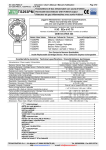
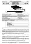
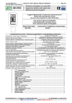
IST-1700.PA01.02
File:i-CE700x-UK.DOC
CENTRAL SYSTEM
CE700P
CE700R
USER MANUAL
TECNOCONTROL S.r.l. - Via Miglioli, 97 20090 SEGRATE (MI) - Tel. 02.26 92 28 90 - Fax 02.21 33 734
http: www.tecnocontrol.it
e-mail: [email protected]
IST-1700.PA01.02
CE700 / User Manual
Page. 2/24
CONTENTS
INTRODUCTION ........................................................................................................ 3
DESCRIPTION............................................................................................................ 3
Central System monitoring ...................................................................................... 5
CE700P Installation instructions ............................................................................. 6
CE700R Installation Instructions ............................................................................. 7
Collegamento alle Unità remote CE390UR.............................................................. 8
Central System Set-up.............................................................................................. 9
Keyboard use, general information ..............................................................................................9
Sensor set-up...............................................................................................................................10
Sensor Deletion ...........................................................................................................................12
Modifying the Sensors Set-up ....................................................................................................12
Sensors Copying .........................................................................................................................13
Sensors Enabling/Disabling........................................................................................................13
Output Set-up ..............................................................................................................................14
Output Deletion ...........................................................................................................................15
Areas Set-up ................................................................................................................................15
Area Deletion ...............................................................................................................................16
Password setting .................................................................................................... 17
Setting the time / Summer time ............................................................................. 17
Power cut................................................................................................................. 18
Backlighting ............................................................................................................ 18
Event visualisation.................................................................................................. 19
Event deletion ......................................................................................................... 19
Remote Units CE390UR Set-Up (Board) ............................................................... 20
Boards Set-up ..............................................................................................................................20
Board Status ................................................................................................................................20
Board Enabling/Disabling ...........................................................................................................20
CE700 Technical Specifications .................................................................................................22
Appendix.................................................................................................................. 23
Table of 4÷20mA transmitters configurable ...............................................................................23
List of Anomaly messages and Alarm ........................................................................................23
Set-up Memorandum Tables .................................................................................. 24
Sensor Set-up ..............................................................................................................................24
Output Set-up ..............................................................................................................................24
Areas Set-up ................................................................................................................................25
TECNOCONTROL S.r.l. - Via Miglioli, 97 20090 SEGRATE (MI) - Tel. 02. 26 92 28 90 - Fax 02. 21 33 734
IST-1700.PA01.02
Page. 3/24
CE700 / User Manual
INTRODUCTION
The CE700 series gas Central Systems presents as useful instruments for monitoring and controlling
areas where there might be the presence of flammable and toxic gases. Together with
TECNOCONTROL gas detectors or any other kind of toxic and flammable transmitter or detector,
they can control quite large areas where to install up to 184 detectors.
This guide describes the CE700 series Central System functions, monitoring procedures of the
system made by the user and set-up procedure, as well as installation and test one to be executed
only by authorised personnel.
DESCRIPTION
Various models compose the CE700-series Central Systems:
CE700P in metal wall-cabinet 360x300x100mm, is composed by a front unit for the data processing
with backlinghted display 40 x 2 characters, foil keyboard, and power supply on the back panel.
CE700R three units 19” rack module, is composed by a front unit for the data processing with
backlinghted display 40 x 2 characters, foil keyboard, and the power supply inside the rack.
CE600P
Wall Cabinet
CE700P
PRINT
7
8
9
ESC
RESET
4
5
6
YES
PAGE
1
2
3
PAGE
0
.
NO
ENTER
CE600R
Rack 19”3U
CE700R
PRINT
7
8
9
ESC
RESET
4
5
6
YES
PAGE
1
2
3
PAGE
0
.
NO
ENTER
The CE700-series Central Systems are designed to manage up to 23 Remote Units CE390UR. The
CE390UR can be connected up to 8 4÷20mA inputs and are able to drive up to 8 outputs (Relays).
The CE700 Central System with the Remote Units CE390UR is able to manage up to 184 detectors
and to drive up to 184 relays output. Both the CE700 and CE390UR are standard AC powered
(230Vac – 50Hz and can also accommodate a 12Vcc battery connection to assure the System
powering in case of power cut. Optionally the CE700-series Central Systems can have 16 internal
input/output.
• Sensors (Inputs): all the inputs, placed on the remote units CE390UR, are configurable for any
type of sensor with linear 4÷20mA signal. The inputs range presents the following item
subdivision:
FAULT- (<1mA) - UNDERFLOW (1 to 3,5mA) - NOR (3,5 to 21mA), or AL1, AL2, AL3, (set
alarm levels) – OVERFLOW (21 to 24mA) – FAULT+ (>25mA).
• Outputs (Relays): for each sensor (input) three alarm levels plus the fault are available and
addressable to whatever output. The outputs consist of relays placed on remote units CE390UR.
Each output can be configured as follows:
Delay ON: with a 250 seconds’ delay when the input exceeds the set alarm level.
Delay OFF: with a 250 seconds’ delay when the input decrease below the set alarm level.
TECNOCONTROL S.r.l. - Via Miglioli, 97 20090 SEGRATE (MI) - Tel. 02. 26 92 28 90 - Fax 02. 21 33 734
IST-1700.PA01.02
CE700 / User Manual
Page. 4/24
Activation ON: with 250 seconds’ activation time and then comes back independently of the
input conditions (even if the input remains over the corresponding alarm level).
Latched output: (if no activation time has been set) can be latched so as it keeps activating
even if the input comes back under the corresponding alarm level. Press the RESET key to
comes back to the normal function a memorized output
Positive logic: the relay is normally activates, in case of power-cut or fault of the relay it comes
in alarm position.
Negative logic: the relay is normally deactivates.
Blackout output: it is possible to assigning one power-cut output working when the system has
been connected to an external buffer battery.
Areas: the inputs can be grouped in areas (max 16) for which up to three outputs can be
configured with the three –alarm levels plus the fault. For each area the output activation can be
executed also when the mean value of the area-grouped input exceeds an alarm level. If the
number of the outputs (relays) allows it, it is possible to address the area alarm level on a
particular number of outputs as well as to address the sensor alarm levels on different outputs.
This way allows assigning up to two outputs for each alarm level when the inputs (sensors) are
configured each in different areas.
Weight: each input (sensor) alarm level can be associated to a weight (max value = 10) for the
realisation of logic ANDs among more inputs of the same area. As an example the output 1 can
be associated to both level 1 of two inputs with weight 5 and level 2 with weight 10. Should this
be the case, the output 1 will be activated if both the inputs exceed the first alarm level and one
of the two sensors exceeds the second alarm level.
Fault: all the inputs have a short-circuit protection system on the power supply or on the sensor.
Should a short-circuit on the power supply occur, the powering to the input in short-circuit is cut
thus causing the input signal fault. After removing the fault cause, press the “RESET” key to
reset the sensor powering. Should a negative-terminal to signal short-circuit occur, the input
signal goes to 0,00mA activating fault signal. The input(s) display indication is flashing.
Events: the system can store up to 999 events comprising alarms, faults, starting, power-cut off,
resetting, that can be re-called at every time.
Password: moreover, it is possible to protect all the configuration value by a code (min. 1 max 8
numbers)
Keys:
•
•
•
•
•
RESET
it is used to reset the latched outputs when the sensor(s) alarm cause has been called off. Or
to reset a sensor powering when a signal short-circuit occur.
PRINT
to enter in print menu (if installed), event visualisation and event deletion.
PAGE
and
.
ENTER
0
ESC
PAGE
to scroll on the display the configured sensors (group of four).
to show on the display Hour, Date and Main Conditions
to confirm and, with normal displayed, to have the mA indication for the sensors’ input.
÷
9
numerical keys
to cancel an operation and to enter in “Password setting” Menu.
YES and NO to confirm and insert the alphanumerical characters in phase of configuration.
NOTE: the label with serial number is inside the door, on lower left part.
TECNOCONTROL S.r.l. - Via Miglioli, 97 20090 SEGRATE (MI) - Tel. 02. 26 92 28 90 - Fax 02. 21 33 734
IST-1700.PA01.02
Page. 5/24
CE700 / User Manual
Central System monitoring
When powered the Central System displays the following message:
CE700 - 2.1 - by TECNOCONTROL
After few seconds, it appears the 30 seconds’ “Wait” message to allow the sensor’s stabilisation thus
avoiding undesired conditions of false alarm:
Wait ... 30
It is possible to cancel this waiting time by pressing
ESC
key (discouraged).
After completing the waiting time, the Central System will display the current conditions of the first
four connected sensors:
17: 0.0%LEL NORM
19: 0 ppm
NORM
Use the
PAGE
and
PAGE
ENTER
key to have mA indication of the input.
17: 4.00mA
19: 4.00 mA
ENTER
AL1
keys to scroll the other configured sensors (always on group of four).
With this screen displayed, press
Press again the
18: FAULT20: 12%LEL
18: 0.00mA
20: 14.23mA
key to come back to the previous screen.
When either one or the other screen are displayed, press the
key to have Hour, Date and Mains
.
Conditions:
16:40:56
Press
.
13/07/98
MAINS ON
key again to come back to the previous screen.
It is possible to access to a detailed input screen pressing the
1
,
2
,
3
and
4
keys
which correspond respectively to the input high on the left, the input high on the right, the input low on
the left and the input low on the right. The input detailed level is as follows:
17 TS292KM
[ 0.0-20.0] %LEL Z01
FAULT0.00mA
Where it is indicated the sensor number, model, range, unit of measurement, the area the sensor
belongs to, the current condition and the mA value.
Press ESC to go to the Set-up Menu (protected with password, if inserted).
TECNOCONTROL S.r.l. - Via Miglioli, 97 20090 SEGRATE (MI) - Tel. 02. 26 92 28 90 - Fax 02. 21 33 734
IST-1700.PA01.02
Page. 6/24
CE700 / User Manual
WARNING: THE FOLLOWING INSTRUCTIONS DESCRIBES ALL THE CENTRAL
SYSTEM SET-UP PROCEDURES AS WELL AS THE INSTALLATION
PROCEDURES TO BE EXECUTED ONLY BY AUTHORISED AND EXPERIENCED
PERSONNEL.
CE700P Installation instructions
This central should be wall mounted by fixing the cabinet by the four holes that are in the corners of
the back panel.
The wiring connections should be executed all on the back panel and on the power supply
The main power supply (230Vac – 50Hz) should be connected to the terminal of the power supply
(Fig.2)
The battery (if presents) should be connected to “BAT+” (Red) terminal and “BAT-“ (Black) terminal
(Fig.2 e 3).
The RS485 serial port, by the 9 pin “D” male connector, is placed on the main board. The cable
should be connected as shown to page 8.
We recommend to anchor the cables to the frame of the cabinet in order to avoid overstress of the
same terminals.
.
305
365
264
324
100
Fig 1 – Dimensions CE700P
Serial Port RS485
9 Pin Male “D” Connettor
Imput
230V ~
Main Board
Power-Supply
Fuse
2A-250V
L
N
5
Red /
13,8VAdjustment trimmer
Black
H
Main presence Led
1
9
13,8 auxiliary output
+
-
Batteriy
Ground
Fuse
6,3A-250V
Fig 3 - Power supply
6
L
9 Pins Female “D”
Connettor
Fig 2 - Central
Black
-
Serial number
Red /
12V –7,2Ah Battery
+
TECNOCONTROL S.r.l. - Via Miglioli, 97 20090 SEGRATE (MI) - Tel. 02. 26 92 28 90 - Fax 02. 21 33 734
IST-1700.PA01.02
Page. 7/24
CE700 / User Manual
CE700R Installation Instructions
The CE700R-Central System should be mounted on a 19” rack cabinet (min. dimensions 3 units).
The wiring connections should be executed on the rack back panel.
The main power supply (230Vac – 50Hz) should be connected to the indicate plug (Fig.2)
The battery (if presents) should be connected to “BAT+” (red) terminal and “BAT-“ (black) terminal
(Fig.2).
The RS485 serial port, by the 9 pin “D” male connector, is placed on the rack back panel. The cable
should be connected as shown to page 8.
We recommend anchoring the cables in order to avoid overstress of the same terminals.
132mm
(3U)
P
R
P
.
240mm
482mm (19”)
Fig 1 – Dimensions CE700R
Serial number
Serial Port RS485
9 Pin Male “D” Connettor
230V
FUSE
BAT
+
RS485
-
Main Power
230V
Ground
Black
Fuse 3A
Fig 2 - Connections
H
Red /
+
5
1
9
Battery
9 Pin Female “D”
Connettor
6
L
TECNOCONTROL S.r.l. - Via Miglioli, 97 20090 SEGRATE (MI) - Tel. 02. 26 92 28 90 - Fax 02. 21 33 734
IST-1700.PA01.02
Page. 8/24
CE700 / User Manual
Collegamento alle Unità remote CE390UR
The CE700R-Central System can be connected up to 23 CE390UR Remote Units.
The connection should be executed between the “SERIAL RS485” output and the first CE390UR
Remote Unit, then between the first CE390UR and the second CE390UR, and so on until the last
CE390UR is connected.
PRI
RE
CE
7
4
1
0
8 9
5 6
2 3
.
CE700
ES
YE
NO
ENT
230Vca
RS485
1
CE390UR
S17
S24
2
CE390UR
S25
S32
3
CE390UR
S33
23
S40
CE390UR
S193
S200
2
The cable should be three-wire shielded cable min. 0,25 mm section. The max distance at
which the last CE390UR should be installed is 1 km.
The connection to the CE700 Central System should be executed by a 9 pin “D” female socket.
Precisely, you should solder the signal H (High) to the pin 1, the signal L (Low) to the pin 6 and the
Ground to the pin 5.
9 Pin Female
“D” Connector
Ground
H
5
Three-Wire Shielded cable
1
9
6
L
On the CE390UR Remote Units, the connection should be executed on terminals H (signal High), L
(signal Low) e V (Ground). (See the CE390UR Remote Unit user manual)
TECNOCONTROL S.r.l. - Via Miglioli, 97 20090 SEGRATE (MI) - Tel. 02. 26 92 28 90 - Fax 02. 21 33 734
IST-1700.PA01.02
Page. 9/24
CE700 / User Manual
Central System Set-up
At the first lighting, after the message:
CE700 - 2.1 - by TECNOCONTROL
And after the waiting 30 seconds’ message:
Wait ...
30
After completing the waiting time, the Central System will display the current condition of the
connected sensors:
17: 12 %LEL AL1
30: 0 ppm NORM
18: FAULT
51: Board 1 offline
Should no remote units are connected, it will be displayed:
ERROR: Board 01 offline
Should no sensors has been configured but the remote units are connected, it will be displayed:
00:00:00
01/01/99
Sensor not configured
Keyboard use, general information
The alphanumerical texts changeable or to insert are displayed by using the slider (black flashing
rectangle). To modify or insert a text have to be used:
Key to cancel leftwards the characters;
PAGE
key to move rightwards the slider; YES and
NO keys to select the characters choosing the followings:
A÷Z [ ] a÷z Space ! “ # $ % & ‘ ( ) * + , - . / 0÷9 : ; < = > ? @
Before confirming the modification or the text inserted, be sure that the slider is on an empty space
on the right of the text. (If the slider stays on the character, this one will not accept any modifications).
Example: if the text displayed have to be modificated from TS293Px into TS293PM, it is necessary
to cancel the “x” with
press
PAGE
key and press repeatedly YES key until the letter “M” appears, after that,
key to move the slider one place right. Only at this point, press
ENTER
key to confirm.
Main Menu “Setup”:
Setup:
1.Sensors
3.Outputs
2.Boards
4.Areas
Sub-Menu 1 “Sensors”
Sub-Menu 2 “Boards”
Sub-Menu 4 “Others”
5.Others
Sensors: 1.Setup
3.Copy
2.Delete
4.Enable
5.Disable
Boards: 1.Setup
3.Enable
2.State
4.Disable
Misc.: 1.Clock
3.Display
2.Main Power
4.Password
TECNOCONTROL S.r.l. - Via Miglioli, 97 20090 SEGRATE (MI) - Tel. 02. 26 92 28 90 - Fax 02. 21 33 734
IST-1700.PA01.02
Page. 10/24
CE700 / User Manual
Sensor set-up
Press ESC key to access to the main menu “Set-up”, after, press the
sotto menu “Sensors” and again the
1
1
key to access to the
key to display:
Sensor number [1-200] :_ _ _
To digit the sensor progressive number which corresponds to sensor-connected input number and
then, press the
ENTER
key to confirm.
Important Note: the sensors numbered from 1 up to 16 (and the outputs from 1 up to 16)
corresponds to 16 optional inputs/outputs that should be installed in the CE700 Central
system
A list concerning the preconfigured sensor defaults can be consulted in the appendix:
Select desired sensor
TS220EA
Use
PAGE
Press the
and
ENTER
PAGE
keys to scroll the list of preconfigured sensors (See table at page 22)
key to enter the selected sensor and to confirm; the display shows:
Name: TS293Px_ _
Should you want to configure an input with a generic sensor not listed in the preconfigured sensor list,
you should choose one sensor (preferably similar to the sensor to configure) and make the
modification at the name as per indicated in Section “keyboard use, general information”.
Example: if the sensor set-up is for a TS293PM for Methane, you choose the TS293Px, cancel the
“x”, select the “M” letter, confirm pressing
ENTER
key and it appears the default unit of
measurement, that is the selected sensor’s. Should you want to modify this setting, it is necessary to
proceed as mentioned above as to the sensor name choice.
Name: TS293PM_ _
Unit: %LEL
Press
ENTER
key to confirm, the it appears:
Alarm type: increasing
With YES key the alarm type can be turned into Decreasing and with NO key into Increasing. This
setting indicates if the alarm interventions should occur when the sensor signal increase or when it
decreases.
Press
ENTER
key to confirm, then it appears:
Alarm Type: increasing
Area : 1_
Up to 16 areas can be selected (See section Areas Set-up). If no area are utilised, let the No. 1
appears to defaults.
TECNOCONTROL S.r.l. - Via Miglioli, 97 20090 SEGRATE (MI) - Tel. 02. 26 92 28 90 - Fax 02. 21 33 734
IST-1700.PA01.02
Press
ENTER
Page. 11/24
CE700 / User Manual
key to confirm, it appears:
Zero: 0.00___
Press
ENTER
key to confirm, it appears the full scale setting preconfigured, that can be modify by
using the numerical keys:
Zero: 0.00___
Range: 100.00__
Press
ENTER
key to confirm, the following screens show the alarm level indication, as well as the
corresponding outputs and weights:
Level 1 :5.00___
Weight : 10_
Output :0_
As mentioned above, the proposed values can be either confirmed by pressing the
ENTER
key or
modified, then confirming and finally going to next setting.
After the third alarm setting, the Central System Software will ask to configure the fault output:
Fault Output :0_
Normally, it is advisable to assign only one relay output to the fault event. Press
ENTER
key to confirm,
the display will show the following screen:
Confirm Data ? :NO
Should you press the YES key and then
ENTER
key, it will appear the following message for few
seconds:
Sensor stored.
Then the software will go back to the Sensor Set-up menu, “Sensor Number”; should you press the
NO key instead, the program will ask you to confirm the cancelling operation:
Confirm sensor deletion ? :NO
Should you press YES key and
ENTER
key, it appears:
Sensor deleted.
On the contrary the program will go back to the “Sensor Number” visualisation. Should you press the
ESC key the program will go back to the “Sensors” sub-menu visualisation.”
Note: the Central System is programmed in a way that if the first sensor is not being configured, it
proposed the previous sensor configuration as first setting. This allows making speedier the
configuration operations if more equal sensors have being configured. Is also possible to copy a
programmed sensor (see the chapter Sensor Copying)
TECNOCONTROL S.r.l. - Via Miglioli, 97 20090 SEGRATE (MI) - Tel. 02. 26 92 28 90 - Fax 02. 21 33 734
IST-1700.PA01.02
Page. 12/24
CE700 / User Manual
Therefore the display will show the following message:
OK for sensor ‘XXnnnXX’ ?
Should the NO key be pressed, the following message will ask to make a choice among a list of
preconfigured sensors; should the YES key be pressed the display shows the set-up parameters,
Name: XXnnnXX_ _ that can be confirmed or modified as described above.
Sensor Deletion
2
From sotto menu “Sensors”, press the
key and the request for digiting the sensor number to
delete will be displayed:
Sensor to delete [1-200] :__
Press
ENTER
key, it appears:
Confirm sensor deletion ? :NO
Press
ENTER
key to go back to the starting menu without executing any kind of modification.
Otherwise, press YES key and then
ENTER
key it will appear the following brief message:
Sensor deleted
The program will come back to the sub menu “Sensors”.
Modifying the Sensors Set-up
To modify an already configured sensor, two different ways are possible:
A – Should you wish to modify the type of sensor, it is better first to delete the sensor to be modified
and then configure it again using the new sensor settings.
B – Should you wish to modify either some alarm levels, or the output or weight selection, it is
sufficient to follow the same procedure as for the sensor configuration (see section Keyboard use,
general information).
From the menu “Sensors” press the
with
ENTER
1
key, then digit the sensor number to be modified, scroll
key the setting parameters until it appears the one to modify, proceed with
ENTER
key until
all the menus have been scrolled and press YES key at the request “Confirm data ?” Press ESC
key and the program will come back to sub menu “Sensors” and to main menu “Set-up”.
TECNOCONTROL S.r.l. - Via Miglioli, 97 20090 SEGRATE (MI) - Tel. 02. 26 92 28 90 - Fax 02. 21 33 734
IST-1700.PA01.02
Page. 13/24
CE700 / User Manual
Sensors Copying
From the main menu “Set-up”, is possible to copy a programmed sensor.
From the sub menu “Sensors” press the
1
key, then press
3
key, and the request for digiting
the sensor number to copy will be displayed:
Sensor to copy [1-200] : _ _ _
then, press the
ENTER
key to confirm.
Digit the sensor number to copy (ei.18), then, press the
ENTER
key to confirm, then it appears:
From [1-200] : _ _ _
Digit the sensor number where its needed to copy the selected one (ei.24), press
ENTER
key to
confirm, then it appears:
From [1-200] : 24 _
To [1-200] : _ _ _
Digit the sensor number up to the one to copy in the selected one. (ei. to insert 5 sensors from 24 up
to 28, digit 28), then press
ENTER
key to confirm. If only one sensor have to be copied digit the same
number inserted before (ei.24). then it appears:
Confirm data ? :NO
Press YES to confirm, then press
ENTER
key, then it appears :
Copy completed
Then program will come back to the menu “Sensor to copy”.
Press ESC key to go back to the sub menu “Sensors” and then to the main menu “Set-up” .
Sensors Enabling/Disabling
It is possible to execute a virtual system exclusion of the sensor without having to disconnect it
physically and deleting it from the program. In this case the Central System will still display the sensor
mA read value, but this value will not have any effect neither on the alarms nor on the Central
System outputs.
From the main menu “Set-up”, press
Respectively press
4
1
key to access to sub menu “Sensors”:
key for Enabling or
5
key for Disabling, the display will require you:
Sensor to enable [1-200] : __
Otherwise:
Sensor to disable [1-200] : __
Digit the selected sensor number to Enable or to Disable and then press
ENTER
key to confirm.
TECNOCONTROL S.r.l. - Via Miglioli, 97 20090 SEGRATE (MI) - Tel. 02. 26 92 28 90 - Fax 02. 21 33 734
IST-1700.PA01.02
CE700 / User Manual
Page. 14/24
Should the sensor be not configured, it will appear:
Sensor not configured
otherwise:
Done
After the Central System Software will go back to the preceding menu.
Press ESC key to go back to the sub menu “Sensors” and to the main menu “Set-up”
Output Set-up
3
From the main menu “Set-up”, press the
key, the display will ask you to digit the output number
to configure:
Output number [1-200] :__
The output number corresponds to the relay position on the CE390UR Remote Units.(ex. the 1st
output relay on the 3rd CE390UR is the output number 33, see figure on page 8 ).
Digit the output number and press
ENTER
key to confirm, then it appears:
Delay ON [0-250] :1__
For the indication of the output activation delay (seconds) beginning from the exceeding of the
corresponding alarm level; press
ENTER
key, it appears:
Delay ON [0-250] :1__
Delay OFF [0-250] :1__
This indicates the delay (seconds) of the output deactivation beginning from the decreasing of the
alarm level below the set threshold; press
ENTER
key, it appears:
Activation ON [0-250] :0__
This indicates the time interval during which the output keeps activating beginning from the exceeding
of the corresponding alarm level. At the end of this time interval, the output returns to its initial
conditions independently of either the input signal value is over the corresponding alarm level or is
below it. Press
ENTER
key, it appears:
Logic: Positive
The software is asking you to select either a normally activated output (positive logic) or normally
deactivated output (negative logic). Select the desired logic using the YES key (Negative) and the
NO key (Positive). Should have been digited the 0 value when the displayed asked for the Time
ON, it will also appear the message:
Logic: Positive
Latched output ? :NO
TECNOCONTROL S.r.l. - Via Miglioli, 97 20090 SEGRATE (MI) - Tel. 02. 26 92 28 90 - Fax 02. 21 33 734
IST-1700.PA01.02
Page. 15/24
CE700 / User Manual
That indicates if the output is to keep activating even if the value come back below the alarm level
previously exceeded. The selection is executed pressing the YES and NO keys.
This question cannot be asked if it has been previously set a Time ON, since there would be a
contrast between the setting of a finite activation time and an infinite activation time represented by
the latched output. Pressing the
ENTER
key, it follows the require:
Confirm Data ? :NO
Press YES key and
ENTER
key to confirm. It will appear the following brief message:
Output stored
The software will automatically go back to the output set-up menu “Output Number”.
Press ESC key to go back to the sub menu “Sensors” and to the menu “Set-up”.
Output Deletion
To delete an output it is necessary to select it, as described in the previous section, and at the first
request:
Confirm Data ? :NO
Confirm with
ENTER
key; in this way, all the settings previously executed for that output will be deleted.
Press ESC key to come back to the sub menu “Sensors” and to main menu “Set-up”.
Areas Set-up
The Areas can be used in different ways, in compatibility with the number of the outputs available:
A – To group more sensors of the same model, making the set of only the Alarm levels, without set
the relay output of the single sensors but only in the Area, to use the same relay outputs for each
sensors.
B – To group more different sensors (i.e.: placed in the same local), with the set of both alarm levels
and different relay outputs for the single sensor and set in the Area the activation of relay outputs
common to all of that sensors.
C – To use sensors with different Weight alarm. For example, if 2 sensors have been both set with
Alarm 2 choose with Weight 5 and assigned to Area 3, the relay output will be activated only when
both sensors exceed the Level 2.
D – To obtain that the output set for that specific area should activate when at least one of the
sensors belonging to that area exceeds the set alarm levels, or when the mean value of all the
sensors grouped in that area exceeds the alarm level.
From the main menu “Set-up”, press the
4
key, and the display will ask you to digit the area
number to set-up:
Area Number [1-16] :__
Use the numerical keys for selecting the area to set-up, press
ENTER
key to confirm, then it appears:
Level 1 output :__
TECNOCONTROL S.r.l. - Via Miglioli, 97 20090 SEGRATE (MI) - Tel. 02. 26 92 28 90 - Fax 02. 21 33 734
IST-1700.PA01.02
Page. 16/24
CE700 / User Manual
Digit the output number (relay) and press
ENTER
Level 1 output :1_
Digit the output number again and press
ENTER
Level 1 output:1_
Level 3 output:__
key to confirm, then it appears:
Level 2 output:__
key to confirm, then it appears:
Level 2 output:2_
Digit the output number once again and press
Level 1 output:1_
Level 3 output:3_
ENTER
to confirm, then it appears:
Level 2 output:2_
Fault output:__
Digit the output number that have to be associated to Fault and confirm with
ENTER
key, then it
appears:
Consider the mean value ? :NO
The display is asking you if the outputs set for that specific area should activate when at least one of
the sensors belonging to that area exceeds the set alarm levels, or when the mean value of all the
sensors grouped in that area exceeds the alarm level.
Use the YES or NO key to select and confirm with
ENTER
key.
Then the display will ask you to confirm the executed settings:
Confirm Data ? :NO
Press YES key to confirm and with
ENTER
it will appear the following brief message:
Area Stored
The Software will go back automatically to the “area number” configuration menu.
Press ESC key to go back to the Main Menu “Set-up”.
Area Deletion
To delete an area it is necessary to select it as described in previous section and at the end of the
selection, when the display ask you:
Confirm Data ? :NO
Confirm with
ENTER
key; in that way all the settings previously executed for that area will be deleted.
Press ESC key to come back to the main menu “Set-up”.
TECNOCONTROL S.r.l. - Via Miglioli, 97 20090 SEGRATE (MI) - Tel. 02. 26 92 28 90 - Fax 02. 21 33 734
IST-1700.PA01.02
Page. 17/24
CE700 / User Manual
Password setting
The password is an access code that, if inserted, is used to protect all the Central System settings
from any tampering through the action of unexperienced people. Should you wish to modify any
setting about inputs, outputs, areas, the same password, events, etc, it will be necessary to digit the
key work in the correct way.
5
From the main menu “Set-up”, press
4
key and it will appear the sotto menu “Others”. Press the
key to access the following message:
Enter password
: _ _ _ _ _ _ _ _
That permits to insert, using keys from 0 to 9, a number with max eight numerical characters.
Press
ENTER
key to visualise the confirmation request message:
Enter password
: * * * * * * * *
Enter password again: _ _ _ _ _ _ _ _
Digit the password again and confirm with
ENTER
key; should the two passwords be equal, the display
will show the following message:
New password stored
Press ESC key more times to come back to normal visualisation. From this moment onwards, any
operation concerning modification of all sorts will be protected by the new entered password.
To delete a password it is necessary to proceed exactly in the same way as well as its setting, but for
leaving the line blank (only spaces).
ATTENTION: we suggest writing and storing the Password. In case of lost call our technical
department.
Setting the time / Summer time
From main menu “Set-up”, press the
Press
1
5
key and it will appear the sub menu “others”:
key to access to the sotto menu “Clock”, press again the
1
key and it appears:
Time [HHMM] 1422_
As described in Section “Keyboard use, general information”, with the numerical keys insert the
adjourned hour with hour (HH) and minutes (MM).
Press
ENTER
key to confirm and to go back to the preceding menu. Press
2
key and it will appear
the current set date:
Date [DDMMYY] 130798_
Press the numerical keys to insert the current date in the day (DD) – month (MM) – year (YY).
Press
ENTER
key to confirm and to go back to the preceding menu. Press
3
key and it will appear
the date of summer time initial:
DST start [DDMM] _ _ _ _
TECNOCONTROL S.r.l. - Via Miglioli, 97 20090 SEGRATE (MI) - Tel. 02. 26 92 28 90 - Fax 02. 21 33 734
IST-1700.PA01.02
Page. 18/24
CE700 / User Manual
Press the numerical keys to insert the summer time initial date for the present year in the day (DD) –
month (MM) format.
Press
ENTER
key to confirm and to go back to the preceding menu. Press
4
key and it will appear::
DST end [DDMM] ____
Press the numerical keys to insert the summer time final date for the present year in the day – month
format.
Press
ENTER
key to confirm and to go back to the preceding menu. Press ESC key repeatedly to go
back to the main menu.
Power cut
The Central System Software provides the opportunity to set-up one relay output in case of a power
cut. Of course external buffer batteries should be installed.
From main menu “Set-up”, press
Press
3
5
key and it will appear the sub menu “Others”.
key and it will appear the following message:
Blackout output [0-200] :0_
Insert, if required, the number of the relay to which have to be associated the signalising power cut.
Press
ENTER
key to confirm and to go back to the preceding menu. Press ESC key repeatedly to go
back to the main menu.
Backlighting
From the main menu “Set-up”, press
Press
3
5
key and it will appear the sotto-menu “Others”:
key and it will appear the following message:
Backlighting [0-99s] :0_
Digit one number from 1 to 98 to set the seconds’ time interval during which the display will keep
illuminating after completing the last operation executed on the keyboard. Should you set the 0 value,
the display will be always off; should you set the 99 value, the display will be always on.
Press
ENTER
key to confirm and to go back to the preceding menu.
Press ESC key repeatedly to go back to the main menu.
TECNOCONTROL S.r.l. - Via Miglioli, 97 20090 SEGRATE (MI) - Tel. 02. 26 92 28 90 - Fax 02. 21 33 734
IST-1700.PA01.02
Page. 19/24
CE700 / User Manual
Event visualisation
Starting from anyone of the sensor screens, press the
PRINT
key and it will appear the following
menu:
[016]: 1. Events 2. Clear
the number put within square brackets indicates the number of the stored events (up to 999).
Press
1
key to ask for the occurred-event initial date in day (DD) – month (MM) – year (YY)
format:
Starting date [DDMMYY] ______
Press ESC key to visualise the last stored event; press
PAGE
key to scroll the events back in the
time. Should you digit one date on the display, it will appear the first stored event during that digited
day. Use the
PAGE
and
PAGE
keys to scroll the events respectively ahead in the time or back in the
time. Should the selected date not contain events, it will appear the following message:
No events at the selected date
And, after few seconds, the immediately preceding event will be visualised.
Should the selected day be former to every stored event, it will be visualised the first stored event.
The first line of the event format includes the hour indication, as well as the date and the event
condition. The second line indicates the input number, the sensor name as well as the input value if it
is in underflow/overflow or alarm conditions (UNDERFLOW, AL1, AL2, AL3, OVERFLOW). In the
events, also the Central System starting, the power cut, the power RETURN, as well as the reset
are indicated.
Event deletion
Starting from anyone of the sensor screens, press the
PRINT
key and it will appear the following
menu:
[016]: 1. Events 2. Clear
the number put within square brackets indicates the number of the stored events (up to 999).
Press the
2
key and the display will ask you to confirm the event deletion operation:
Do you want to clear events file? :NO
Press NO key and confirm with
ENTER
Press the YES key and confirm with
Events
key to go back to the preceding menu.
ENTER
key to cancel all the events present in memory:.
file cleared
After the above message, it will return back to the preceding menu automatically.
TECNOCONTROL S.r.l. - Via Miglioli, 97 20090 SEGRATE (MI) - Tel. 02. 26 92 28 90 - Fax 02. 21 33 734
IST-1700.PA01.02
Page. 20/24
CE700 / User Manual
Remote Units CE390UR Set-Up (Board)
Boards Set-up
From the main menu “Set-up”, press the
1
2
key, it appears the sub menu “Board”. Then press
key, and the request for digiting the board number to set-up will be displayed:
Board number [1-23] :_ _
Then press
ENTER
key, it appears:
Present ? : NO
Press YES key and then
ENTER
key it will appear the following message:
Confirm data ? : NO
Press YES key and then
ENTER
key, it will appear the following brief message:
Board stored
Press
ESC
key, the program will come back to the menu “Board”.
Board Status
From the main menu “Status”, press
2
key, it appears:
Board status
18:ERR
27:DISAB
Press
ESC
the program will come back to the menu “Board”.
Board Enabling/Disabling
It is possible to execute a virtual system exclusion of a Remote Unit CE390UR (Board) without
having to disconnect it physically and deleting it from the program. In this case the Central System
will still display the sensor mA read value, connected to the Disabled CE390UR, but this value will not
have any effect neither on the alarms nor on the outputs.
From the main menu “Board”, respectively press
3
key for Enabling or
4
key for Disabling,
the display will require you:
Board to enable [1-23] : _ _
Board to disable [1-23] : _ _
Digit the Board number to enable or to disable and then press
ENTER
key, it appears:
Done
Then the program will come back to the preceding menu. The disable board will be displayed DISAB
(Board Status)
Press
ESC
key more times to come back to the main menu.
TECNOCONTROL S.r.l. - Via Miglioli, 97 20090 SEGRATE (MI) - Tel. 02. 26 92 28 90 - Fax 02. 21 33 734
IST-1700.PA01.02
CE700 / User Manual
Page. 21/24
CE700 Technical Specifications
Power Supply
230 Vac (-15/+10%) - 50 Hz (±10%)
Minimum power at 230V
11VA
Inputs
n.1 RS485 serial port
Working temperature with battery
+5 ÷ +40 °C
Buffer battery (on request)
n.1 Pb 12 Vcc - 7,2 Ah
Battery Life
About 4 hours’ full charge
Display
2-line x 40-characters back lighted LCD
Keyboard
20 membrane keys
Dimensions
CE700P = 365x305x105 mm
CE608R = Rack 19" 3U
Weight
CE700P = 5 Kg
CE700R = 3Kg
TECNOCONTROL S.r.l. - Via Miglioli, 97 20090 SEGRATE (MI) - Tel. 02. 26 92 28 90 - Fax 02. 21 33 734
IST-1700.PA01.02
CE700 / User Manual
Page. 22/24
Appendix
Table of 4÷20mA transmitters configurable
Advised Alarm Level
Min
Max
Unit
AL1(2)
AL2
ALL
Range
Range
NH3
0
300
ppm
20
50÷100
TS220EA
10 (3)
CO
0
300
ppm
100
200
TS220EC
25(2)÷50
H2S
0
100
ppm
10
20
50
TS220EH
(3) (4)
(4)
O
0
25
%
22
TS220EO
18,5
19.5
2
SO2
0
100
ppm
10
20
50
TS220ES
LPG
0
20
%LIE
10
20
TS292KG
7 (3)
METHANE
0
20
%LIE
10
20
TS292KM
6 (3)
LPG
0
20
%LIE
10
20
TS293KG
7 (3)
METHANE
0
20
%LIE
10
20
TS293KM
6 (3)
0
100
%LIE
10÷15
20÷30
TS293Px (1) FLAMMABLE
7 (3)
(1)
All the sensors TS293P series are calibrated with range 100%LEL, it will change only the
calibration gas.
(2)
(3)
(4)
If required.
It is advisable to insert inferior pre-alarm levels.
Decreasing Alarm.
MODEL
GAS
List of Anomaly messages and Alarm
No configure sensors
FAULTUNDERFLOWAL1
AL2
ALL
OVERFLOW+
FAULT+
Board nn offline
Password not correct
No sensors has been configured
The input signal is less then 1 mA.
The sensor could be damaged, no connected or not powered.
The input signal is between 1 end 3,5mA.
The sensor could be out of calibration at the beginning of the scale.
The alarm 1 level has been exceeded and the configured output is
activated.
The alarm 2 level has been exceeded and the configured output is
activated.
The alarm 3 level has been exceeded and the configured output is
activated.
The input signal is between 21 and 24 mA.
The sensor is detecting gas but it exceeds its full-scale
The input signal is more then 24 mA.
The sensor could be damaged, or is detecting gas but it exceeds its
full-scale.
The Central Unit doesn’t receive data from the Remote Unit
CE390UR (Board).
The board could be not connected, fault or not powered.
A wrong access code has been inserted.
TECNOCONTROL S.r.l. - Via Miglioli, 97 20090 SEGRATE (MI) - Tel. 02. 26 92 28 90 - Fax 02. 21 33 734
IST-1700.PA01.02
Page 23/24
CE700 / User Manual
Set-up Memorandum Tables
It is advisable to photocopy and compile these tables as memorandum of the effected set-up
Sensor Set-up
CE390UR number :
Sensor Number 17÷200
Sensor Name
Unit of measurement (ppm, LEL or %)
Alarm Type (Increasing or Decreasing for Oxygen)
Area (1÷16)
Min. Full Scale (Normal = 0)
Max. Full Scale
AL1
Output 1 (Relay Number)
Weight 1 (Normal = 10)
AL2
Output 2 (Relay Number)
Weight 2 (Normal = 10)
ALARM
Output 3 (Relay Number)
Weight 3 (Normal = 10)
Fault (Relay Number)
Output Set-up
CE390UR number:
Output Number 17÷200 (Relay)
Hysteresys ON (from 0 to 250 Seconds)
Hysteresys OFF (from 0 to 250 Seconds)
Time ON (from 0 to 250 Seconds)
Positive Logic (NO/YES)
Latched Output (NO/YES)
IST-1700.PA01.02
Pag. 24/24
CE700 / User Manual
Areas Set-up
CE700
Area Number
1
2
3
4
5
6
7
8
9
10
11
12
13
14
15
16
Level 1 Output
(Relay Number)
Level 2 Output
(Relay Number)
Level 3 Output
(Relay Number)
Fault Output
(Relay Number)
#-----------------------------------------------------------------------------------------------------------------------------------------------------------------------------------------------------------------Password
Central Mod.
Serial Number
ATTENTION: It is advisable to write and store the Password in a secure place. In case of loss of the Password, contact our Assistance Department
TECNOCONTROL S.r.l. - Via Miglioli, 97 20090 SEGRATE (MI) - Tel. 02. 26 92 28 90 - Fax 02. 21 33 734