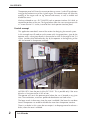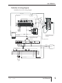
1
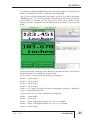
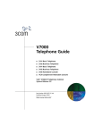
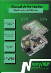
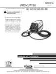
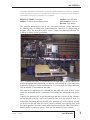
AN-SERV-010
THIS INFORMATION PROVIDED BY AUTOMATIONDIRECT.COM TECHNICAL SUPPORT IS SUPPLIED "AS IS", WITHOUT ANY GUARANTEE OF
ANY KIND. These documents are provided by our technical support department to assist others. We do not guarantee that the data is suitable for your
particular application, nor do we assume any responsibility for them in your application.
PRODUCT FAMILY: SureServo
Number: AN-SERV-010
Subject: Sureservo linear displacement
Date issued: Jul-6-2010
Revision: First edition
This example demonstrates how to use a Sureservo to control a linear movement
by selecting parts available from AutomationDirect. After that it is shown how to
program a PLC, the servo drive and a 6 inch C-more micro operator interface. The
machine is shown in the figure below:
This is a device that moves a saw horizontally installed over a movable table to any
of four desired positions entered by an operator with the help of a rack and pinion
mechanism through a maximum distance of 134 inches from the Home position.
The servomotor is mounted over the table.
The mechanical department has defined that the table will move 0.6284 inches
when the servomotor rotates 1 revolution. The acceleration and deceleration time is
0.6 s.
Typically the operator will set the desired target position with one of the 4 buttons
on the operator interface, and he will need to move it on the range of 0 to 134
inches from the Home position possibly with precision of 1 thousandth of an inch.
At the start of the job, when the servo system is enabled, the machine shall go to
the Home position, located at some inches from the one of the sides. The Home is
determined by a proximity sensor. There are also overtravel limit switches.
1st Ed.
07/10
Luis Miranda
1
AN-SERV-010
The operator panel will show the current position on screen 1 and will have buttons
to trigger the motion to any of the 4 given targets. The second screen will allow the
entering of the targets and use Jog forward and reverse, as well as enable and
disable the servo.
We have selected to use a PLC D0-05DD and an operator interface EA1-S6ML to
control the positions of the saw. The figure below shows the same arrangement with
a C-more micro of 3.1 inches, instead of the 6 inch operator interface panel.
Control concept
This application note details some of the actions for designing the control system.
In this example we will need to run the motor with 4 target positions, given by the
operator, with a value given directly in thousand of an inch in the range of 0 to 134
inches, variable values defined every day by the operator at the beginning of the
shift and entered in the operator interface.
Operator interface
134 inches motion
Home sensor
The transfer of target values and the writing of digital inputs is done though
MODBUS RTU, from the port 2 of the PLC DL05. This is possible only if the servo
drive has a firmware version 2.105 or later.
The operator will see in the operator panel where the saw is located at any given
time. The acceleration, maximum speed and deceleration are fixed values.
The home search is done every time the servo is enabled if the home has not been
found. The operator can enable or disable the servo from the operator interface.
There is no brake in this system but one output is to be programmed to release a
brake, when the servo is enabled.
2
Luis Miranda
AN-SERV-010
In this case the motion is ideally suited to be absolute motion with internal registers.
The servo is defined arbitrarily as slave 2 for the PLC. The operator panel is the
master for the PLC. They are located in different networks.
The Home sensor as well as the overtravel limit switches and external fault have
been left directly wired to the servo drive.
Steps for the execution of the control
This is the sequence of operations that shall be followed in this example to get the
system up and running:
- Define the control hardware to be used including the wiring
- Create the wiring diagram
- Select and set the communication parameters.
- Read the status of the servo though MODBUS, using the RX instruction.
- Measure the communication speed in transactions per second.
- Write data to servo (Set it to write data in RAM memory only.
- Make the details of the block transfer parameters.
- Make the code for reading an writing interlocks
- Define the block transfer parameters
- Define the values of P0-04 to P0-11 and the value of P3-08.
- Define the main parameters on the servo.
- Factor of revolutions versus displacement for targets defined
- Current position math defined
- Some C-more micro programming concepts defined
- Add the revolutions and counts of displacement and scale it to show the current
displacement.
- Read servo output data (To be used the status data in P4-09 to create logic for the
operation)
- Digital inputs to be used for commanding the servo defined.
- Reading the servo status from PLC.
- Operator code to write the desired target positions and send to the PLC.
- Additional code to make the operation automatic.
- Code to use the output status on PLC and operator panel.
- Test the program together with the servo and the operator panel.
- Program the operator interface
- Test the program and correct any errors. May be you need to tune the servo.
- Prepare a copy of the ladder and the servo parameters in this document.
- Prepare documentation to describe the operator what it is necessary to do to
operate the machine. May be leave as screen text data on the Operator panel.
1st Ed.
07/10
Luis Miranda
3
AN-SERV-010
Definition of the control hardware
The different hardware parts of the control system are:
- Servo motor SVL-204B
- Servo drive SVA-2040, firmware 2.105
- Power cable SVC-PFL-020
- Encoder cable SVC-EFL-020
- Terminal block board ZL-RTB50
- ZipLink cable ZL-SVC-CBL50
- Cable to link PLC to servo SVC-232RJ12-CBL-2
- PLC D0-05DD
- Programming cable (for panel and PLC) EA-MG-PGM-CBL
- Power supply PS24-075D
- Proximity sensor AM1-AN-1A
- Operator panel EA1-S6MLW
- Relay 782-2C-24D
- Socket 782-2C-SKT
- Surge suppresor ASD-BSDM-250
- Fuses and wiring as well as an enclosure for mount the control system.
4
Luis Miranda
AN-SERV-010
Definition of wiring diagram
See below the initial wiring diagram
SVC-232RJ12-CBL-2
DV-1000CBL
Port 2
Port1
D0-05DD PLC
Orange
0V
AUTOMATIOND IRECT
MODE
Yellow
LG
G
X1
X0
X3
X2
X4
C1
X6
X5
C2
X7
Y1
Y0
Y2
Y3
Y4
ENTER
NEXT
Y5
Sureservo
+V
AC Power
AC(L) AC(N) C0
Relay
L1
L2
S
T
U
V
W
0V
P
D
C
+24V
–
24 VDC
GND
L2
L1
120/240
VAC
AC Power
ZIPLink Kit Cable connects
to SureServo drive CN1
connector
EA1-S6MLW
0V
ZIPLink Kit Cable connects
to SureServo drive CN1
connector
F1 F2 F3 F4 F5
C
N
3
+
AC Power
Operator interface
C
N
2
Power Supply
GND
L1 L2
C
N
1
R
Power cable to motor
ZIPLink Kit Terminals
ZIPLink Kit Terminals
VDD
DI2-
COM+
DI1-
DO1+
OB
Brown
Black
TGND PULSE V-REF /PULSE GND COM-
COM-
Home sensor
+
NPN type
–
AM1-AN-1A
COM- 0Z
COM-
DI6-
DI8-
/OB /OZ
Blue
DI8- DI7- DI6- DI5- DI3- PULL HI /SIGN SIGN
DI7-
DO4- DO5- DO5+
/OA
PULL HI
DO2+
DO1-
DO2-
DO3+
DO4+ DO3- DO3+ DO2- DO2+ DO1- DO1+ DI4- DI1- DI2- COM+ GND GND VGND MON2 MON1 VDD T-REF GND VCC OA
07/10
REVERSE LIMIT
FAULT STOP
1st Ed.
FORWARD LIMIT
COMHome sensor
Luis Miranda
5
AN-SERV-010
Select and set the communication parameters for servo
The servo drive, the slave in the network, has registers or internal memory locations
with parameters whose content causes the servo work the way that the designer of
the control system wants it to work.
These registers have addresses you specify, shown in chapter 6 of the user manual
of the servo drive.
For example, if you want to read if the servo is with or without fault or read the type
of fault, in case there is an alarm, you can read the the register 40002, that
corresponds to the P0-02 parameter.
You can easily create a control system with a servo using a serial MODBUS
network.
The servo communication configuration is done with the keypad of the servo drive.
Set P3-00 parameter to the desired slave address. In this case we will use the value
2, that is to say, servo drive slave 2.
Then set a value 3 in P3-01, that defines the transmission rate as 38,4 kBaud. This
value also must be set in the configuration of PLC port 2.
P3-02 defines the protocol and the configuration of the same one. In this case, let
us select 8.
Finally, we set the P3-05 value according to the system of communication RS-232,
with a value of 0.
6
Luis Miranda
AN-SERV-010
Communication parameters for PLC.
The communication parameters in PLC DL05 are configured with the software
DirectSOFT5 and we show
the adopted values in the
adjacent figure.
The configuration on the Port
2 is saved in RAM Memory.
That is, it is possible that the
port set up be lost after the
PLC has a period of 4 days
without power.
In this case we can also do the
port set up with ladder code,
which is retained in Flash
memory and in this case there
is no need of power to keep
the set up stored.
See the set up on the DL05
user manual or in one of the
application notes on the web
site of AutomationDirect. Let
us leave the other values as
default values.
At this time, we are only trying to connect the PLC with the servo. Later, we will
connect the C-more micro panel to the port 1of the DL05 PLC. For convenience, we
can use a H0-ECOM to allow the connection of the panel to port 1, the servo to
port 2 and the laptop with DirectSOFT to the H0-ECOM module inserted on the
slot available. This is not a must, only a convenience, but for testing purposes this
layout becomes very convenient.
Then we must connect the PLC with the servo drive.
Port 1 Port 2
H0-ECOM
1st Ed.
07/10
7
AN-SERV-010
Read the status of the servo though MODBUS, with RX instruction
In order to be able to read the data from the servo drive and to check that
connections are correct, I suggest to run the program shown in the following diagram.
Set a value 10 in the P2-08 parameter with the keyboard to configure all the values
of the servo as default values). It will appear errors ALE14, ALE15 and ALE13 on the
display, and this is normal.
The fault ALE14 in the servo display indicates that the overtravel limit switch is
activated, and this is true, since of P2-15 default (that corresponds to the DI6 input
function) it set as 22, P2-16 (that corresponds to the DI7 input function) is set as 23
and P2-17 (that corresponds to the DI8 input function) is set as 21. Same for ALE14
and ALE15.
To make these errors disappear we may set P2-15 to P2-17 to a value 0 to disable
the function of each input in DI6, DI7 and DI8 or wire the proper switches there.
In order to clear the faults press the “up and down arrow” keys on the keypad
simultaneously, clearing any error can be there, or it is also possible to power cycle
the servo drive to get the same function.
Next, be sure that the value of the motor code is set in the P1-32 parameter.
The axis of the motor should turn freely (Do not couple the servo to the machine
until the tests of the programs have been done) and the data that is contained in the
memories P0-00 up to P0-08 can be read. These memories have MODBUS
addresses 40001 up to 40009, as it is in the following table and described in the
user manual, in chapter 6.
Parameter
P0-00
P0-01
P0-02
P0-03
P0-04
P0-05
P0-06
P0-07
P0-08
Value
2.105
14
0
1
1
0
0
0
0
MODBUS address
40001
40002
40003
40004
40005
40006
40007
40008
40009
Description
Software version
Fault code
Display code
Analog monitor
Status monitor 1
Status monitor 2
Status monitor 3
Status monitor 4
Status monitor 5
This is the explanation of the operation:
SP116 is a bit in the PLC that turns ON when the communication is happening and
itis called “busy”. It indicates when the PLC is transmitting data through the
8
Luis Miranda
AN-SERV-010
communication in port 2, and turns OFF when the data transmission is completed.
Therefore, in the first scan, the instruction RX is executed if the servo slave is ready
to communicate. See more details in the DL05 manual.
Let us say that the PLC scan takes 2 ms; when beginning the transmission the contact
of bit SP116 closes and makes the rung true to allow the transmission to be executed.
When establishing the transmission, SP116 turns ON; when the transaction
completes, SP116 contact is closed again and then another transaction begins and
thus it follows continuously. Typically the transmission takes more than the PLC scan
time. In this case it is approximately 17 ms.
The values in the selected range go to the memories of the PLC V3000 to V3010,
according to the following table:
Parameter
P0-00
P0-01
P0-02
P0-03
P0-04
P0-05
P0-06
P0-07
P0-08
Value
2.105
14
0
1
1
0
0
0
0
MODBUS address
40001
40002
40003
40004
40005
40006
40007
40008
40009
PLC memory
V3000
V3001
V3002
V3003
V3004
V3005
V3006
V3007
V3010
Description
Software version
Fault code
Display code
Analog monitor
Status monitor 1
Status monitor 2
Status monitor 3
Status monitor 4
Status monitor 5
Also, it is necessary to set some function in P0-04 until P0-08 parameters to be able
to monitor what it is desired to see in the PLC and later in the operator panel.
We will change the values in the parameters according to the following table:
Parameter Value
MODBUS address
PLC memory
Description
P0-00
2.10
40001
V3000
Software version
P0-01
14
40002
V3001
Fault code
P0-02
0
40003
V3002
Drive Status
P0-03
1
40004
V3003
Analog monitor
P0-04
1
40005
V3004
Current revolutions
P0-05
0
40006
V3005
Current counts
P0-06
6
40007
V3006
Current rpm
P0-07
11
40008
V3007
Current % torque
P0-08
13
40009
V3010
DC Bus voltage
The values in V3000 until V3010 are all signed decimal values.
When the parameter changes have been done, you can move the shaft of the
servomotor and it will be possible to observe that the content of V3005 memory
shows the same number than the display on the servo when the shaft of the motor
moves (parameter P0-02 should be set to 0). This fact allows to check that the
communication has been established.
1st Ed.
07/10
Luis Miranda
9
AN-SERV-010
Measure the communication speed in transactions per second
How can we measure the PLC scan time and how many transactions are happening
per second? Using Data View in DirectSOFT to monitor the V-memory V7775
which is the current scan time. Or use the window of “scan time”.
As we know, when a communication transaction begins, SP116 will turn ON, and
then, using this bit, we can count how many times the SP116 contact closes in 1
second, for example with a simple counter. Remember that a counter counts
whenever is a transition of the input from OFF to ON. See the diagram of the figure
below with the corresponding code ladder and the explanations in each line.
C0 closes one scan every
second
Every time C0 closes the
current count of CT100 is
loaded to the accumulator.
The instruction OUT reads
what is in the accumulator
and copies to V3770
Here the counter CT100
counts every time the bit
SP116 turns on. The
CT100 counter current
value goes to zero every
time C0 closes.
Here is the same rung
programmed before, used
to configure the network
You can read V3770 in Data View, as in the adjacent figure, and can see that the
result is 60 counts every second. Since there
are 1000 milliseconds in a second, 1000/60 ms
is approximately 17 ms.
You can also see that the vmemory:
V3000 has the firmware version,
V3004 has the current number of revolutions,
V3005 the current number of counts,
V3010 the DC bus voltage of the servo, etc.
This it is a good method to determine the
transmission speed.
revs
pulses
DC volt
/second
10
Luis Miranda
AN-SERV-010
Writing to the servo
When already proven the communication link between the PLC and the servo, we
should see what algorithms to do in the PLC to be able to give the servo the values
to be written into it.
Remember that we are still in the stage of creation of the program on the master
PLC. Also it is necessary to define how data is written to the servo drive.
We have said previously that we want to write values in the servo.
RX and WX should not execute at the same time otherwise the communication will
fail.
A simple way we could do this would be the following:
At the beginning, the
closed contact SP116
and C1 allow the reading
with RX of 9 consecutive
registers, but immediately will turn ON C1
with the SET instruction,
and waits for SP116 to
be turned OFF.
C1 will close but SP116
will be ON (busy).
When
the
reading
transaction is completed,
the writing begins with
instruction WX; it writes 3
registers;
C1 is turned OFF with
the Reset instruction.
The PLC would be reading and writing once at the time in sequence.
Nevertheless, it is necessary to consider the following:
The servo drive has two types of memory, RAM and EEPROM. In RAM memory data
can be written at any time but the memory EEPROM can be written a limited
number, of the order of 100000 times. The parameters that do not change in time
are written typically in EEPROM memory and with this memory it is not necessary
to maintain the drive powered. When powering the servo drive, these values will
be still stored in the memory.
In RAM memory this is not possible and the data only stay stored if the servo drive
is powered. If we want to write continuously to the drive RAM memory, we should
set the value of P2-30 parameter as 5; but this value is not retained in memory
EEPROM.
1st Ed.
07/10
Luis Miranda
11
AN-SERV-010
Clearly it is not possible that the setting of this value be done by the machine
operator when the servo powers on. Therefore it is necessary to write a value of 5
to this memory when the drive powers ON or otherwise the servo will reach the
limit of writings and the device will not be functional anymore.
One of several ways is to use a comparison function reading the content of P2-30
parameter and on the basis of that value it is executed a writing on that parameter.
That is, if the reading on that parameter shows that the value is not 5, we will set a
bit or flag to force a 5 into the same memory.
It can be created an interlock such that it is not executed this function anymore
when
P2-30
(MODBUS
address 40543 [or 21E in
hexadecimal format or V1036
in octal]) has a 5 in its content.
Here it is advisable the use of
the block transfer parameters
P0-09 up to P0-16, that are
configurable
parameters
allowing to read or write data
in
consecutive
servo
addresses, which is better than
to read data in random
addresses (Not consecutive).
For that, we will configure P009 (Modbus address 40010)
with the keyboard (By default
with value 407) as 21E, that
causes that this parameter be
defined as P2-30. Then we
will increase the reading of 9
registers in RX to 10, to
include P0-09.
Note that we have to force a
value of 5 into the content of
the register that corresponds
to P2-30. For that, we have to
set a V-memory with a
constant 5. This is done on a
first scan on rung 1 and the
memory is V3772. We also
create other constants that are
necessary for the program. We
should also reset the bits C0 to
C2.
In order to test this step, turn off the servo and P2-30 will reset to off. Then, when
turning the servo on, you can monitor V3011 with Data View to see the value there.
12
Luis Miranda
AN-SERV-010
You will observe that the PLC did not took notice that the servo was powered off.
Then, it is necessary to create an interlock in such a way that the PLC resets C0 to
C2 when the servo goes from “servo not ready” to “servo ON”. For this we will read
the data in P4-09.
We added the rung 1 for constants we will need later. See below.
When SP0 closes: Load the
constant
5
to
the
accumulator.
The instruction OUT reads
what is in the accumulator
and copies the value to
V3772
Load the constant 500 to the
accumulator.
The instruction OUTD reads
what is in the accumulator
and copies the value to
V3766
Load the constant 157 to the
accumulator.
The instruction OUTD reads
what is in the accumulator
and copies the value to
V3776
Load the constant 10 to the
accumulator.
The instruction OUTD reads
what is in the accumulator
and copies the value to
V3756.
Load the constant 0 to the
accumulator.
The instruction OUTD reads
what is in the accumulator
and copies the value to
V3011.
C0 and C2 are set to OFF
The transactions statistics are in rungs that were explained on page 8.
Test it again to be sure that the code is working as you want.
Notice that, as an option to reduce the transactions per second figure, we can
eliminate parameters P0-00 to P0-03 on the reading instruction RX, thus transferring
less words and we will add one register for purposes to be seen later.
Now, we have created a code that makes interlocks to allow the writing once when
the value in P2-30 is a value of 5; that is, the next instruction WX will be executed
any given time if the value in P2-30 be 5.
C3 is the flag that advices that the value in P2-30 is a 5. When C3 is ON, we have
permission to write to the servo over RAM memory.
1st Ed.
07/10
Luis Miranda
13
AN-SERV-010
By now we have the MODBUS RTU communication working but we have not set
the servo parameters for position operation.
Use of block transfer registers
Let us go back to the discussion on the reading of up to 13 registers in the memories
V3004 to V3020. Why this is convenient?
Because the block transfer parameters P0-09 to P0-16 are “configurable
parameters”, that is, the ones that could be changed to read or write any desired
address in the servo drive.
We have done so for P0-09. We can read the 13 registers and configure the data in
a convenient way for our specific purpose.
We have the following settings, so far:
Parameter
P0-04
P0-05
P0-06
P0-07
P0-08
P0-09
P0-10
P0-11
P0-12
P0-13
P0-14
P0-15
P0-16
Value MODBUS address PLC memory
1
40005
V3004
0
40006
V3005
6
40007
V3006
11
40008
V3007
13
40009
V3010
21E
40010
V3011
10F
40011
V3012
110
40012
V3013
224
40013
V3014
111
40014
V3015
112
40015
V3016
225
40016
V3017
109
40017
V3020
Description
Current revolutions
Current counts
Current rpm
Current % torque
DC Bus voltage
Set not as default, as parameter P2-30
Default is P1-15 -Target 1 revolutions
Default is P1-16 -Target 1 counts
Default is P2-36 -Target 1 velocity
Default is P1-17 -Target 2 revolutions
Default is P1-18 -Target 2 counts
Default is P2-37 -Target 2 velocity
Default is P1-09 -Velocity command 1
Parameters P0-10 to P0-16 may be changed to our convenience or leave as they are.
We will be using the parameters P0-10 to P0-13 for other functions explained after
this section. In this example it is convenient to define P0-10 as P4-09, P0-11 as P115, P0-12 as P1-16 and P0-13 as 407. The rest can continue to be the default (Or,
if necessary, to configure to read or write other
values)
Note that the values there are to be written only
by the keypad and this is not reported by the
report that Sureservo PRO software generates.
However, when the values are written there and
the servo drive is power cycled, the setting is
retained in EEPROM memory.
The final setting is shown on the parameter
table at the end of the document.
The adjacent figure shows the content of 8
consecutive memories as seen with Data View in DirectSOFT. This is one way to
determine that we are really communicating with the servo. C3 could also indicate
this action, but this reading of data is an assurance.
14
Luis Miranda
AN-SERV-010
Definition of P3-08
Let us define the value of parameter P3-08, the input mask.
The values of digital inputs are defined by the content in the P3-08 parameters and
the P4-07.
P3-08 is a parameter that allows us to control digital inputs with MODBUS. After
setting the input mask word P3-08 to define which bits in P4-07 will act as
hardwired inputs or virtual inputs o perform a particular function. P4-07 is a conduit
for activating any of the 16 inputs (DI1 to DI16). Turning any particular bit in P407 that correspond to each one of the digital inputs of the servo drive, will signal
each input to execute the pre-programmed function. Note that P4-07 takes on dual
functionality: It still serves as an indicator for the digital input status as seen in the
servo drive display an may be used with MODBUS to write to the digital inputs that
have been configured as virtual digital inputs.
If any of the eight less significant bits on P3-08 is a 1, digital inputs DI1 until DI8
are used as virtual digital inputs with MODBUS; we call them virtual digital inputs
as opposed to real digital inputs. We can imagine each bit of P3-08 as a permissive
to use MODBUS for each one of the defined functions.
The 8 most significant bits have preassigned functions.
We will set each one of the P3-08 bits according to the following table:
Bit
Digital
Assigned
Code Description.
order input
value
0
DI1
101 Servo Enable
1
1
DI2
104 Clear command
1
2
DI3
124 Home sensor
0
3
DI4
0 Disabled
0
4
DI5
0 Disabled
0
5
DI6
22 Reverse overtravel limit switch, opens on overtravel
0
6
DI7
23 Forward overtravel limit switch, opens on overtravel
0
7
DI8
21 External fault stop, opens on fault
0
8
DI9
108 Command Trigger - predefined
1
9
DI10 111 PCS0 - Bit de selection 0 de position - predefined
1
10
DI11 112 PCS1 - Bit de selection 1 de position - predefined
1
11
DI12 113 PCS2 - Bit de selection 2 de position - predefined
1
12
DI13 102 Alarm reset- predefined
1
13
DI14 127 Home search command - predefined
1
14
DI15 137 JOG Forward- predefined
1
15
DI16 138 JOG Reverse - predefined
1
}
}
}
}
3
0
F
F
In this case, we must set P3-08 as FF03. The default value is 0.
Notice that Home sensor, overtravel limit and external fault stop are hardwired. The
inputs DI1 and DI2 and DI8 to DI16 are used with MODBUS.
1st Ed.
07/10
Luis Miranda
15
AN-SERV-010
Main parameter setting
- P0-04 Set as 1, current revolutions
- P0-05 Set as 0, current counts.
- P0-06 Set as 6, servo shaft speed.
- P0-07 Set as 11, % torque.
- P0-08 Set as 13, DC bus voltage.
- P0-09 Set as 21E, corresponding to P2-30.
- P0-10 Set as 409, corresponding to P4-09.
- P1-01 Operation mode, that by default is 0, set as 1 (Pr mode) 0r 101.
- P1-32 Selection of the stop mode, changed to 1 from value 0.
- P1-33 set as 0, absolute mode
- P1-34 Acceleration time: it was defined as 600 ms.
- P1-35 Deceleration time: 600 ms.
- P1-36 S-curve: set as 30 arbitrarily.
- P1-47 Home search definition : set as 223.
- P1-48 Home search fast speed; set as 600 rpm arbitrarily.
- P1-49 Home search creep speed; set as 60 rpm arbitrarily.
- P1-50, Revolutions offset from home sensor, for example, 9 revolutions.
- P1-51, Count offset from home sensor.
- P1-55, left as 2174 rpm.
- P2-10, DI1, set as 101, that is, servo enable
- P2-11, DI2, set as 104, clear command, to zero the counts after home position.
- P2-12, DI3, set as 124, defined as a home sensor normally open
- P2-13, DI4, set as 0, disabled.
- P2-14, DI5 , set as 0, disabled
- P2-15, DI6, set as 22, as reverse overtravel limit; it is a normally closed contact.
- P2-16, DI7 , set as 23, as forward overtravel limit; it is a normally closed contact.
- P2-17, DI8, set as 21, as external fault stop; it is a normally closed contact.
Note from the table on the previous page that bits 8 to 15 are predefined functions for
digital inputs.
- P2-18 , DO1, as 102, that is the output servo OK.
- P2-19 , DO2, as 109, that is the output Home completed.
- P2-20 , DO3, as 105, that is the output At position.
- P2-21 , DO4, as 107, that is the output Active fault.
- P2-22 , DO5, as 101, that is the output servo ready.
- P2-36 Position 1 velocity set to 2174 rpm.
- P2-50 Clear command, set to 1.
- P3-08 Digital input mask, set as FF03.
Note that in order to store the parameter values into the servo drive, parameter P2-30
shall be set as 0 and, when the values have been entered, you should power cycle the
servo drive, that is, power OFF and then ON the servo drive.
16
Luis Miranda
AN-SERV-010
The concept of absolute position control will be so that, after the operator enables
the servo drive with DI1, the servo will make the home search after 3 seconds of
servo enable.
When the servo finds the home position, we will zero the position (0 revs and 0
counts) and then after that we can have a reference point to the target position on
P1-15 and P1-16. Recall that P4-07 is the value that contains the digital inputs.
The digital inputs could be real inputs or virtual inputs defined with MODBUS.
Repeating the explanation, if any of the eight less significant bits on P3-08 is a 1,
digital inputs DI1 until DI8 are used as virtual digital inputs with MODBUS; we call
them virtual digital inputs as opposed to real digital inputs.
We have arbitrarily associated to P4-07 the following definitions:
Bit
order
0
1
2
3
4
5
6
7
8
9
10
11
12
13
14
15
Digital
Code
input
DI1
101
DI2
104
DI3
124
DI4
0
DI5
0
DI6
22
DI7
23
DI8
21
DI9
108
DI10
111
DI11
112
DI12
113
DI13
102
DI14
127
DI15
137
DI16
138
Description.
Servo Enable
Clear command
Home sensor
Disabled
Disabled
Reverse overtravel limit, opens on overtravel
Forward overtravel limit, opens on overtravel
External fault stop, opens on fault
Command Trigger - predefined
PCS0 - Bit de selection 0 de position - predefined
PCS1 - Bit de selection 1 de position - predefined
PCS2 - Bit de selection 2 de position - predefined
Alarm reset- predefined
Home search command - predefined
JOG Forward- predefined
JOG Reverse - predefined
Assigned value
in P3-08
1
1
0
0
0
0
0
0
1
1
1
1
1
1
1
1
PLC
bit
N/A
N/A
N/A
N/A
N/A
N/A
N/A
N/A
C100
N/A
N/A
N/A
C101
C102
C103
C104
We can define the P0-11 parameters and subsequent in such way than they are the
values of position in P1-15 (P0-11), P1-16 (P0-12) and the digital inputs in P4-07
(P0-13). Therefore, the code of line 9 is such that it is written in 3 consecutive
registers. The initial associated V memory on the PLC will be the memory V2000.
In this way, we should set the parameters as follows, with the keyboard.
Parameter Value MODBUS address PLC memory Description
1st Ed.
P0-04
1
40005
V3004
Current revolutions
P0-05
0
40006
V3005
Current counts
P0-06
6
40007
V3006
Current rpm
P0-07
11
40008
V3007
Current % torque
P0-08
13
40009
V3010
DC Bus voltage
P0-09
21E
40010
V3011
Set not as default, as parameter P2-30
P0-10
409
40011
V3012
Set not as default, as parameter P4-09
P0-11
10F
40012
V3013
Set as position command 1, revolutions
P0-12
110
40013
V3014
Set as position command 1, counts
P0-13
407
40014
V3015
Set as input status
07/10
Luis Miranda
17
AN-SERV-010
P0-11 will be the desired revolutions with the value 10Fhex equivalent to P1-15.
P0-12 will be desired counts with the value 110hex equivalent to P1-16.
P0-13 will be the word with the digital inputs with the value 407hex equivalent to
P4-07.
You may select other block transfer parameters, if it is necessary in your application.
Current position math
We should calculate the current position in V7362, after reading the revolutions and
fractions from the servo drive.
See the ladder code on the figure below to implement this.
- We know that the current revolutions are in V3004 and the current counts in
V3005. We can execute a calculation to get the current position expresssed in
revolutions to be displayed in thousandths of an inch.
The client may test that the panel communication link is working together with the
servo. The way to do that is to force some values, because we have not done all the
set up. But is is possible to see the current position by rotating the shaft of the servo.
Notice that it could be a small error due to truncation.
Calculation of current position in inches when reading from servo
LD
_On
SP1
Servo actual rev
V3004
13
BCD
OUT
Revoluc BCD
V3761
LD
Servo act. pulse
V3005
BCD
OUT
Pulses BCD
V3760
LDD
Pulses BCD
V3760
DIVD
Constant 10
V3756
The servo contains
the current revs and
pulses
in
parameters P0-04
and P0-05, that are
read into v3004
and V3005.
The
value
is
transformed into a
value of revolutions
in a double word
BCD
V3760.
In order to do some
logic, we divide the
value by 10 and put
the result into
V3700.
OUTD
Aux position
V3700
Revoluc BCD
V3761
K63
Revoluc BCD
V3761
K63
K1
GTS
14
18
Luis Miranda
Pulses BCD
V3760
K6530
Depending on the
value of the current
value, we have to
change
the
algorithm and for
that purpose we use
subroutines,
AN-SERV-010
Revoluc BCD
V3761
K63
Pulses BCD
V3760
K6530
Revoluc BCD
V3761
K127
Revoluc BCD
V3761
K64
Revoluc BCD
V3761
K127
Pulses BCD
V3760
K3062
15
Revoluc BCD
V3761
K127
K127
Pulses BCD
V3760
K3062
Revoluc BCD
V3761
K128
Revoluc BCD
V3761
K190
Pulses BCD
V3760
K9594
Revoluc BCD
V3761
K190
Revoluc BCD
V3761
K215
Revoluc BCD
V3761
K190
Pulses BCD
V3760
K9594
Revoluc BCD
V3761
K191
Revoluc BCD
V3761
K215
17
Each subroutine will
put the result into
V7362.
The calculation is
done in segments of
40 inches, or the
equivalent count in
the servo.
Revoluc BCD
V3761
K190
16
Revoluc BCD
V3761
K2
GTS
K3
GTS
See
below
the
development of 2
subroutines.
The
complete section is
shown at the end of
this document.
K4
GTS
Subroutines 1 and 2
Note that:
- We use the lower
and upper words of
16 bits for the value
of revolutions and
counts and each one
is converted to
binary format with
the instruction BIN.
The complete section
is shown at the end of
this document.
1st Ed.
07/10
Luis Miranda
19
AN-SERV-010
On the same token, it would be important to the operator to show the current
position. The servo will report the revolutions and the counts and this value will
have to be scaled.
Factor of revolutions versus displacement
As concept, we will have target positions A, B, C and D, to be defined by 4 entries
on the operator panel. By request of the mechanical department, we will have to
clamp the numbers in the range between 3inches to 134 inches.
Every time the operator select one target and enters the data, the target value of
revolutions on the servo will change accordingly.
We had defined that V2000 is the value of the target revolutions in P1-15, it is
logical that we will have the V2001 values as the value of the target counts, that is
zero so far, and V2002 will have the bits that go to P4-07.
The PLC will have to do some math to relate the linear distance to revolutions and
counts. This is what we will explain now.
Since we know that one revolution of the servo shaft will displace 0.6284 inches,
we can create the proper scale. We know that the maximum displacement is 134
inches and the precision shall be close to 2 thousands of an inch.
That is, 134.000 inches entered by the operator should be equivalent to 134/0.6284
or 213.2399 revolutions. This is the math we have to implement on the PLC.
Notice that there are integer revolutions and fractions. The revolution value should
go to the parameter P1-15. The counts will go to the parameter P-16.
The operator will only define the inches to be displaced from the Home position in
thousand of an inch units.
Now, recall that we have an operator interface that will write 4 numbers, such as
34.250, 56.789, 89.1243 and 102.500 inches in the PLC in double memories
V4000 to V4006, arbitrarily defined.
These values will be saved in the PLC and will be transferred to the target in the
servo at the proper time.
The selected target value has to be scaled and separated into 2 numbers that are in
binary format (Or decimal, as called in DirectSOFT software).
We have a small problem, and it is that the PLC calculates only up to 9999,9999 in
the accumulator. We will have to split the calculation into sections using
subroutines. The value, in thousandth of an inch shall be divided by 0.6284, which
is the same as multiplying 10,000/6,284, or 2,500/1,571.
The ladder code on next pages explains how to do this using the unique memory
V7366. We will copy the selected target to V7366 in the code. The calculation is
done in segments and for that subroutines 5 tyo 8 are used, in the same manner that
the ones done for the calcutlaion of the current position scaling.
Remember that the value of target revolutions shall go to V2000 and the target
counts into V2001.
20
Luis Miranda
AN-SERV-010
1st Ed.
07/10
Luis Miranda
21
AN-SERV-010
Now, it is the time to do some operator panel
programming.
C-more micro programming
We will describe here how to program the
objects on the operator interface. Recall that
we want a screen 1 with the current position
and 4 buttons to command the motion to any
of the 4 targets. The second screen will have
the settings. See the idea on the adjacent
figure.
Open the C-more micro program and create a new project by clicking on the
button “Start a project”. Give a project name (for example, Sierra project) then
select the HMI; the HMI type will be the one you are using. The PLC protocol will
be Automation Direct Ksequence and click OK. The
next screen will show up:
The position is portrait in this
example.
Next, we will create a
numeric display object to
show the current position.
Click on the menu Object
and then select Indicator and
then Numeric display and
click on it. The cursor will turn into a cross symbol and then drag it by holding
the left mouse button and form a rectangle with it.
When you finish the dragging, the numeric display dialog box will show up and
then you can fill up the data. See it on the adjacent figure. The main features are
explained on next page.
22
Luis Miranda
AN-SERV-010
Text Size: Click on the down arrow to select the Text Size of the number to be
displayed. In this case we will select 32X 32.
32
Data Display Tag: Click on the down arrow to select a Tag Name. In this case we
will select CURRENT POSITION . Click on the button at the right with 3 dots and
other dialog box will show up, as in the adjacent figure. Fill up according to the
data on the figure. Tag name Type shall be BCD 32 bit.
Number of Digits: Click on the Up or Down arrows to select the number of Total
and Fractional digits to be displayed. set
as TOTAL 6 & FRACTIONAL 3.
Suffix: Click on the field to enter a
common Suffix value that will always be
displayed. In this case we will select
inches.
inches
You can get familiar with the object
properties.
Other fields are not important at this time.
You can read more on the on line help.
Click on the button ADD to return to the
main dialog box and then click OK.
Note that the object is displayed where you have made the rectangle. Drag it to the
top of the screen. You should see an object similar to the following:
You may drag it to the desired position, if necessary; you can also give other size
and shape. then, save to the disk
We will create 2 buttons to jump to other screens, screen 2 and 3, that arbitrarily
are defined as settings and instructions. Of course, the client can customize the
operator panel as desired. More than 90 screens are possible, even though this is
not practical.
In order to to this, please click on Object and then select Control and Screen
change pushbutton. Click again and the cursor will turn into a cross.
Drag it forming a rectangle somewhere under the numeric display object. It will
pop up a dialog box as follows:
1st Ed.
07/10
Luis Miranda
23
AN-SERV-010
Change the field Text with the
words Go to settings and in
the field Go to: select other
screen and set it as number 2
and you may set other
properties here.
In the same way, set other
change screen button to go to
screen 3, that will be called
Go to instructions.
instructions You can
copy the object and then
change the properties. For
that, select the change screen
button by clicking into it and
then go to the menu Edit and hit “copy”. Then got other submenu “Paste”. A copy
will show up over the original set, offset and showing dots on the corners. Drag it
to the right of the existing one.
Now we can right-click on the bottom text object and a submenu will show up.
Click on the submenu Object Properties and change the necessary fields.
You can relocate the objects to align with the upper ones. You may change the frame
to other, to distinguish from the previous one.
On the same way, you may change the properties of the numeric display.
The result and the tags related to each object are shown on the following figure:
Tag V7362
screen 2
24
Luis Miranda
screen 3
AN-SERV-010
This project can be downloaded to the panel for testing purposes by clicking on the
button “Send Project to Panel”. Set the panel to Setup mode.
You can also simulate the behavior of the panel on the PC by clicking the button
“Simulate panel”. This function provides the possibility to show what you will see
on the panel. For example, you can click on the numeric entry object and the
display will show a keypad that can be clicked to enter a number, as you do on the
panel.
More instructions are found on the on line Help of the software.
We will create the functionality for the buttons on the operator panel. We will have
defined functions that are different on each screen.
On the screen 1 we will create the following arrangement:
Button 1 - Go to target A
Button 2 - Go to target B
Button 3 - Go to target C
Button 4 - Go to target D
Button 5 - It is spare. We could also create an emergency stop here, if desired by
using a servo disable command.
On the screen 2 we will create the following arrangement:
Button 1 - Servo enable
Button 2 - Alarm reset
Button 3 - Spare. To be programmed to turn ON Y5 as example
Button 4 - Spare. To be programmed to turn ON C333 as example
Button 5 - Servo disable
1st Ed.
07/10
Luis Miranda
25
AN-SERV-010
The C-more micro panel 5 buttons has associated bits of a word that it is necessary
to define. We will go to the menu SETUP and then select PLC <-> Panel.
The following dialog box will show up; we will create a Start address in V7350:
The explanation of the 3 words related to the panel functions are in the figure
above, but for now we are interested on register V7351.
Let us define the functions of the operator interface as follows
F1 => C110 Servo enable; the servo enable shall be set by the operator.
F2 => C100 Command trigger;
F3 => C101 Alarm reset; this should also be commanded by operator
F4 => spare
F5 => C102 Servo disabled; it shall be commanded by the operator.
We will relate the word V7351 value to any of the C bits, as follows:
If the button F1 is pressed, V7351 will change to a 1 BCD.
If the button F2 is pressed, V7351 will change to a 2 BCD.
f the button F3 is pressed, V7351 will change to a 4 BCD.
If the button F4 is pressed, V7351 will change to a 8 BCD
If the button F5 is pressed, V7351 will change to a 10 BCD.
26
Luis Miranda
AN-SERV-010
Defining the digital inputs to be used for commanding the servo
With these considerations we will implement more ladder code on the PLC.
Recall that V7351 is
the word associated
to the panel key.
When the content of
V7351 is 1 the key F1
has been pressed.
C140 is turned on this
case.
When the content of
V7351 is 2 the key F2
has been pressed.
C140 is turned on this
case.
When the content of
V7351 is 4 the key F3
has been pressed.
C140 is turned on this
case.
When the content of
V7351 is 8 the key F4
has been pressed.
C140 is turned on this
this case.
When the content of
V7351 is 10 the key
F5 has been pressed.
C146 is turned on this
this case.
1st Ed.
07/10
Luis Miranda
27
AN-SERV-010
In the test at AutomationDirect, we used a H0-ECOM to connect DirectSOFT to the
PLC; the Port 1 has the Panel and the Port 2 is connected to the servo drive.
In order to create a trigger command after one of the buttons have been pressed, we
created the following code:
When the bit C140 is
activated, the action
sets the bit C100, which
is the trigger bi
When C100 is On, the
timer counts for 200 ms
and will turn ON T4 after
this time.
When T4 is ON, the bit
C100 is reset to OFF.
We will create a static text object with the descriptions of the functions to the
operator panel. in order that the operator can identify the proper button. Of course,
other possibility is to engrave the function on the empty labels supplied with the
panel.
We have other action on the screen 2 buttons. See below:
C333
28
Luis Miranda
AN-SERV-010
We are ready to create the screen 2 and screen 3.
In screen 2 we will set 4 numeric entry
objects to define the position targets data
to be used. See the adjacent figure about
the text created.
We may have to add a JOG forward and a JOG reverse later on this project, for the
rare case that the tool get the overtravel limit switch activated or any need to test
the motion. This can be set with a touch
screen button. Finally, we have to identify the
buttons for screen 2. The figure above is the
probable result.
Screen 3 can be just text, as shown on the
adjacent figure. Of course, the client should
set the proper instructions for the specific
machine. The instructions can also be several
pages with navigation buttons there.
1st Ed.
07/10
Luis Miranda
29
AN-SERV-010
Now is the time to check the connections between the PLC and the servo.
In order to turn the servo outputs ON, we can use the parameter P4-06.
P4-06 shall be set to 1 to force DO1 to ON. When pressed the ENTER key, the
Display will show OP 01 and the XO LED of the PLC will turn ON. In the same
manner, when set to 2, and then pressed the ENTER key, the Display will show OP
02 and the X2 LED of the PLC will turn ON.
N/A DI8 DI6 DI4
DI2
Now it is the time to turn the PLC outputs ON, when
the proper input is turned ON and the effect will be
seen on the servo by observing the display when set for
the parameter P4-07. See the figure attached for having
an idea of how each input that is active is seen.
Having this wiring test done, we are at the moment toEDs:
test the program as it has been set up.
Off
N/A
DI7
DI5
Off
On
On
On
Off
On
On
On
On
DI3
DI1
Press F1 on the operator panel. The output Y4 will turn ON. The shaft of the motor
shall be locked since now the servo is enabled and you will hear a typical sound of
current flowing through the windings of the servomotor
Press F5 on the operator panel. The output Y4 will turn OFF. The shaft of the motor
shall not be locked anymore.
The Home search shall begin automatically after the servo is enabled, if there is no
signal Home completed ( P2-19 shall be set as 109). We have not done this logic.
For now, let us configure the command Home search 2 seconds after the servo is
enabled. One way to implement this it is as follows:
C110 enables the servo
and turn ON the output
Y4
When Y4 is turned ON
and Home has not been
found , C4 turns ON
The timer T2 begins to
count the time up to 4
seconds when C4 is
turned ON
When C4 is ON AND the
current value of the T2
timer is over 2 s, C102 is
turned ON
When The timer reaches 4
seconds, C4 is reset, as
well as C102
30
Luis Miranda
AN-SERV-010
After the Home is completed, there is no need to do home search again. When the
Home is completed, we should clear the current counts (And revolutions) to get the
0 counts at this time and allow a proper indication of the current position. This is
shown on the following rungs of the next figure.
When the Home has been
found, the bit C5 is set .
When C5 is ON, the timer
T3 begins to count up to 3
seconds.
V2002.1 is turned ON for
200 ms to clear the current
position
when
the
timer
T3
completes 3 seconds, the
bit C5 is reset.
We should transport the necessary digital input to the servo though MODBUS. This
is one way to implement it; C100 has to be turned ON at the proper time:
When C100 turns ON the eighth bit
of the word V2002 is turned ON.
This will give the command to move
to the servo.
When C101 turns ON the bit 12 of
the word V2002 is turned ON. This
will clear alarms on the the servo
drive.
When C102 turns ON the bit 13 of
the word V2002 is turned ON. This
will give the servo the command to
move to search for the home sensor.
When C201 turns ON the bit 14 of
the word V2002 is turned ON. This
will give the command to JOG
forward.
When C200 turns ON the bit 15 of
the word V2002 is turned ON. This
will give the servo the command to
JOG reverse.
At this time we can test again the program.
The data can be seen with Data View using the
proper formatting. See the adjacent figure to see
how to check that the Alarm reset button C101
has been pressed. Bit 12 turns ON.
1st Ed.
07/10
Luis Miranda
31
AN-SERV-010
Using the output status data in P4-09
We need the servo digital output data for some actions on the PLC program. We
know that we are getting data continuously on the word V3012.
The following part of the ladder program shows how this can be accomplished.
When the bit 0 on the register P409 is ON, the servo is ON. This
turns ON C300.
When the bit 1 on the register P409 is ON, the Home search has
been completed. This turns ON
C301.
When the bit 2 on the register P409 is ON and home is completed,
the servo is at position. This turns
ON C302.
When the bit 3 on the register P409 is ON, the servo is at fault. This
turns ON C303.
When the bit 4 on the register P409 is ON, the servo is ready. This
turns ON C304.
When the bit 5 on the register P409 is ON, the servo is at torque
limit. This turns ON C305.
The bit C300 can be used for resetting the logic on rung 1, to avoid that the servo
communications is not well established.
All the bits that show the status of the servo can be used for other purposes on the
ladder code. For example, to show the status on the screen 1 of the operator panel.
Testing the program
You may want to be sure that the hardwired inputs are working properly. Also that
the speeds are the ones you want.
The next step is to turn on the servo and the PLC and the operator panel. The current
position should be 0 inches, even though it might not be there. The Home not
found banner will be on the top. Also, the servo is Disabled and Ready.
The transactions/s should be about 25 to 48 Transactions/s.
If significant lower than from a value close to this, please troubleshoot the problem.
You should press the Goto Settings button to go to screen 2 to load target values
and test that the servo is moving to the corresponding position.
32
Luis Miranda
AN-SERV-010
Before proceeding with this, it is possible to rearrange and add more functionality
to the operator interface panel.
We have added the transactions per second on screen 1 as well as the status
indicators. Notice that the transaction counts per second has decreased. See the
adjacent figures for one possible option.
Screen 2
Screen 1
Write targets in the “numeric entries” by touching the object. The numeric keypad
will show up. Clear the number that is there by touching the key “CLR”.
Press the button F1, Servo enable and the servo will move to find the Home sensor.
When this is done, the servo will stop moving and after a short period, the Current
position will go back to zero ( 0.000 inches).
Press the Screen1 button to go back to the screen 1.
The banner at the top has changed to Home completed.
completed
It is checked that the number is not greater than 130 inches. If greater or equal than
130 inches, it clamps the value and forces a 130 inches on the target. But this has
not been transferred to the servo. For that to happen, we should press one of the
buttons F1 to F4 on the screen 1.
When this is done, the logic on the PLC triggers the motion. The servo will move
to the corresponding number of revolutions and counts.
To come back to other position, we can repeat the action, that is, after at position,
press other button. It will move to the selected target.
This is the operation. If everything works as described, the project has been done.
If the motion has some oscillations, you may need to execute some tuning. Tuning
is not covered in this technical note.
But you should document the operation for the operator to have a description of
what the machine will do, how to troubleshoot, How to reset alarms if any, etc.
1st Ed.
07/10
Luis Miranda
33
AN-SERV-010
This concludes the programming of the PLC and basic configuration of the servo.
At this time, we have a PLC scan time of 10 ms average, with excursion to 14 ms
and 8 ms.
The transaction/second are about 42 or 43 T/s , that is, the reading occurs every 47.6
ms. This is, 1000[ms]/42 [transactions is 23.8 ms. since for every reading there is a
writing, we multiply that value by 2=> 23.8x2 = 47.6 ms.
What to do if we need more updates per second?
A - We can reduce the number of points to be read and written.
B- If we use a faster master, such as the D0-DCM or the F0-CP128 on the DL05, or
other PLC with more Baud rate, such as the Click PLC, the reading can occur faster.
On next pages are shown the tag database on the operator panel, The ladder code
and the parameters selected on the servo.
34
Luis Miranda
AN-SERV-010
_FirstScan
SP0
LD
1
K5
OUT
C146
Constant 5
V3772
LDD
K2500
This rung defines some constants, such as the scaling of the linear engineering units
into revolutions, and vice-versa, and initialize some variables. This rung turns true
OUTD
Constant 2500
V3766
for one scan only on power up and after the timer T33 is turned ON.
LDD
K1571
OUTD
FACTOR
V3776
LDD
K10
OUTD
Constant 10
V3756
LD
K0
OUT
P2-30
V3011
OUT
V2002
C0
C3
RST
This rung defines the T33 timer
C3
TMR
2
T33
K15
T33
C146
OUT
3
This rung generates a pulse every second, lasting one scan
_1Second
SP4
C0
PD
4
Here we save the CT100 counter current value just when the C0 pulse is on.
C0
LD
5
CTA100
OUT
TRANSACT/S
V3770
Here we count the communication transactions in a period of 1 second
SP116
CNT
6
CT100
K999
C0
This is the reading instruction; it reads 7 consecutive words from servo
SP116
7
C1
LD
Kf202
LD
K14
LDA
O3004
RX
TA4
C1
SET
1st Ed.
07/10
Luis Miranda
35
AN-SERV-010
C2 turns ON if the content of P2-30 is NOT 5
P2-30
V3011
C1
K5
C2
8
SET
This is one writing instruction when C2 is ON and it writes one word to parameter P2-30
SP116
C2
LD
9
Kf202
LD
K2
LDA
O3772
WX
TA11
If the content of P2-30 is 5, then resets C2 and sets C3
P2-30
V3011
K5
C2
10
RST
C3
OUT
This is other writing instruction when C3 is ON and it writes 3 words to servo
SP116
C2
C1
C3
LD
11
Kf202
LD
K6
LDA
O2000
WX
TA13
C1
RST
Calculation of current position in inches when reading from servo
LD
_On
SP1
Servo actual rev
V3004
12
BCD
OUT
Revoluc BCD
V3761
LD
Servo act. pulse
V3005
BCD
OUT
Pulses BCD
V3760
LDD
Pulses BCD
V3760
DIVD
Constant 10
V3756
OUTD
Aux position
V3700
This rung and next ones send the execution to subrutines
Revoluc BCD
V3761
K63
Revoluc BCD
V3761
K63
K1
GTS
13
36
Luis Miranda
Pulses BCD
V3760
K6530
AN-SERV-010
Revoluc BCD
V3761
K63
Pulses BCD
V3760
K6530
Revoluc BCD
V3761
K127
Revoluc BCD
V3761
K64
Revoluc BCD
V3761
K127
Pulses BCD
V3760
K3062
Revoluc BCD
V3761
K127
K2
GTS
14
Revoluc BCD
V3761
K127
Pulses BCD
V3760
K3062
Revoluc BCD
V3761
K190
Revoluc BCD
V3761
K128
Revoluc BCD
V3761
K190
Pulses BCD
V3760
K9594
Revoluc BCD
V3761
K190
Revoluc BCD
V3761
K215
K3
GTS
15
Revoluc BCD
V3761
K190
Pulses BCD
V3760
K9594
Revoluc BCD
V3761
K191
Revoluc BCD
V3761
K215
K4
GTS
16
Calculation of desired position in thousandth of inches into revolutions
LDD
C140
INCHES
V7366
17
MULD
Constant 10
V3756
OUTD
V6600
Limitation of high end range to 134.0 inches
V6601
K134
C140
LDD
18
K134000
OUTD
INCHES
V7366
Limitation of low end range to 3.0 inches
V6601
K3
C140
LDD
19
K3000
OUTD
INCHES
V7366
C140
V7367
K4
K5
GTS
C140
V7367
K4
V7367
K8
K6
GTS
C140
V7367
K8
V7367
K12
K7
GTS
20
21
22
1st Ed.
07/10
Luis Miranda
37
AN-SERV-010
C140
V7367
K12
K8
GTS
23
C140
C120
SET
24
C140
LD
25
V7371
BIN
OUT
servo RPM
V2000
LD
Result
V7370
BIN
OUT
servo steps
V2001
C120
TMR
26
T4
K4
T4
C120
RST
27
This rung is true when the F1 button is pressed on screen 2
V7351
K1
V7350
K1
28
LDD
V4000
OUTD
INCHES
V7366
C140
OROUT
This rung is true when the F2 button is pressed on screen 2
V7351
K2
V7350
K1
29
LDD
V4002
OUTD
INCHES
V7366
C140
OROUT
This rung is true when the F3 button is pressed on screen 2
V7351
K4
V7350
K1
30
LDD
V4004
OUTD
INCHES
V7366
C140
OROUT
This rung is true when the F4 button is pressed on screen 2
V7351
31
K8
V7350
K1
LDD
V4006
OUTD
INCHES
V7366
C140
OROUT
38
Luis Miranda
AN-SERV-010
This rung is true when the F5 button is pressed on screen 2
V7351
K2
V7350
K2
Reset alarm
C101
OUT
V7351
K4
V7350
K2
Spare 1
Y5
OUT
V7351
K8
V7350
K2
Spare 2
C10
OUT
V7351
K10
V7350
K2
Spare 3
C112
OUT
33
34
35
36
This rung allows to give the command servo enabled
Enable servo
C110
Spare 3
C112
Servo enable DI
B2002.0
OUT
37
Servo enable DI
B2002.0
Brake output
Y4
OUT
Brake output
Y4
Home complet. DO
C301
C4
38
SET
C4
TMR
39
T2
K25
C4
TA2
Do home search
C102
OUT
K20
40
T2
C4
41
RST
Home complet. DO
C301
C5
42
SET
TMR
C5
CLEAR position
T3
43
K30
2.8 seconds after the home is completed, the servo current position is set to zero.
This is done by writing to the digital input word P4-07
TA3
44
CLEAR position
T3
45
1st Ed.
07/10
K28
Clear command DI
B2002.1
OUT
C5
RST
Luis Miranda
39
AN-SERV-010
When C120 closes the servo begins the motion. This is done by writing to the digital input
word P4-07
Trigger DI
B2002.8
OUT
C120
46
Writing to the digital input word P4-07
Reset alarm
C101
Alarm reset DI
B2002.12
OUT
47
Writing to the digital input word P4-07
Do home search
C102
48
Home search DI
B2002.13
OUT
Writing to the digital input word P4-07
JOG Fwd DI
B2002.14
OUT
C201
49
Writing to the digital input word P4-07
JOG rev DI
B2002.15
OUT
C200
50
Reading from P4-09 to the word V3012 for virtual digital outputs
Servo ON DO
C300
OUT
B3012.0
51
Reading from P4-09 to the word V3012 for virtual digital outputs
Home complet. DO
C301
OUT
B3012.1
52
Reading from P4-09 to the word V3012 for virtual digital outputs
B3012.2
Home complet. DO
C301
53
At position DO
C302
OUT
Reading from P4-09 to the word V3012 for virtual digital outputs
B3012.3
54
Active fault DO
C303
OUT
Reading from P4-09 to the word V3012 for virtual digital outputs
B3012.4
55
56
40
Luis Miranda
Servo ready DO
C304
OUT
END
AN-SERV-010
SBR
K1
LDD
_On
SP1
Aux position
V3700
58
MULD
FACTOR
V3776
DIVD
Constant 2500
V3766
OUTD
Current position
V7362
Aux position
V3700
LDD
K0
K0
59
OUTD
Current position
V7362
60
RT
SBR
K2
_On
SP1
LDD
Aux position
V3700
62
SUBD
K63653
MULD
FACTOR
V3776
DIVD
Constant 2500
V3766
ADDD
K40000
OUTD
Current position
V7362
63
1st Ed.
07/10
RT
Luis Miranda
41
AN-SERV-010
SBR
K3
_On
SP1
LDD
Aux position
V3700
65
SUBD
K127306
MULD
FACTOR
V3776
DIVD
Constant 2500
V3766
ADDD
K80000
OUTD
Current position
V7362
66
RT
SBR
K4
_On
SP1
LDD
Aux position
V3700
68
SUBD
K190961
MULD
FACTOR
V3776
DIVD
Constant 2500
V3766
ADDD
K120001
OUTD
Current position
V7362
69
42
Luis Miranda
RT
AN-SERV-010
SBR
K5
_On
SP1
LDD
INCHES
V7366
71
MULD
Constant 2500
V3766
DIVD
FACTOR
V3776
MULD
Constant 10
V3756
OUTD
Result
V7370
72
RT
SBR
K6
_On
SP1
LDD
INCHES
V7366
74
SUBD
K40000
MULD
Constant 2500
V3766
DIVD
FACTOR
V3776
MULD
Constant 10
V3756
ADDD
K636541
OUTD
Result
V7370
75
1st Ed.
07/10
RT
Luis Miranda
43
AN-SERV-010
SBR
K7
_On
SP1
LDD
INCHES
V7366
77
SUBD
K80000
MULD
Constant 2500
V3766
DIVD
FACTOR
V3776
MULD
Constant 10
V3756
ADDD
K1273074
OUTD
Result
V7370
78
RT
SBR
K8
_On
SP1
LDD
INCHES
V7366
80
SUBD
K120000
MULD
Constant 2500
V3766
DIVD
FACTOR
V3776
MULD
Constant 10
V3756
ADDD
K1909611
OUTD
Result
V7370
44
81
RT
82
NOP
Luis Miranda
AN-SERV-010
List of parameters on the servo drive
Parameter
1st Ed.
Value
P0.00 - Software Version
P0.01 - Drive Fault Code
P0.02 - Drive Status (Front panel display)
P0.03 - Analog Monitor Outputs
P0.04 - Status Monitor 1
P0.05 - Status Monitor 2
P0.06 - Status Monitor 3
P0.07 - Status Monitor 4
P0.08 - Status Monitor 5
P0.09 - Block transfer parameter 1
P0.10 - Block transfer parameter 2
P0.11 - Block transfer parameter 3
P0.12 - Block transfer parameter 4
P0.13 - Block transfer parameter 5
P0.14 - Block transfer parameter 6
P0.15 - Block transfer parameter 7
P0.16 - Block transfer parameter 8
P0.17 - Output function status
2.105
0
0
1
1 (Current revolutions)
0 (Current counts)
6 (Current speed in rpm)
11 ( Current % torque)
13 (Current DC bus voltage)
21E (Set as P2-30)
409 (Set as P3-08)
10F (Set as Pos cmd 1 revs)
110 (Set as Pos cmd 1 counts)
407 ( Set as Input status)
112 (As default)
225 (As default)
109 (As default)
0
P1.00 - External Pulse Input Type
P1.01 - Control Mode and Output Direction
P1.02 - Velocity and Torque Limit
P1.03 - Output Polarity Setting
P1.04 - Analog Monitor Output Scaling 1 (CH1)
P1.05 - Analog Monitor Output Scaling 2 (CH2)
P1.06 - Analog Velocity Command Low-pass Filter
P1.07 - Analog Torque Command Low-pass Filter
P1.08 - Position Command Low-pass Filter
P1.09 - Preset Velocity Command / Limit 1
P1.10 - Preset Velocity Command / Limit 2
P1.11 - Preset Velocity Command / Limit 3
P1.12 - Preset Torque Command / Limit 1
P1.13 - Preset Torque Command / Limit 2
P1.14 - Preset Torque Command / Limit 3
2
101
0
0
100
100
0
0
0
100
200
300
100
100
100
07/10
Luis Miranda
45
AN-SERV-010
P1.15 - Position 1 Command (Revolutions)
P1.16 - Position 1 Command (Counts)
P1.17 - Position 2 Command (Revolutions)
P1.18 - Position 2 Command (Counts)
P1.19 - Position 3 Command (Revolutions)
P1.20 - Position 3 Command (Counts)
P1.21 - Position 4 Command (Revolutions)
P1.22 - Position 4 Command (Counts)
P1.23 - Position 5 Command (Revolutions)
P1.24 - Position 5 Command (Counts)
P1.25 - Position 6 Command (Revolutions)
P1.26 - Position 6 Command (Counts)
P1.27 - Position 7 Command (Revolutions)
P1.28 - Position 7 Command (Counts)
P1.29 - Position 8 Command (Revolutions)
P1.30 - Position 8 Command (Counts)
P1.31 - Motor Code
P1.32 - Motor Stop Mode Selection
P1.33 - Position Control Mode
P1.34 - Acceleration Time (Internal Indexer)
P1.35 - Deceleration Time (Internal Indexer)
P1.36 - Accel / Decel S-Curve
P1.37 - Inertia Mismatch Ratio
P1.38 - Zero Velocity Output Threshold
P1.39 - Target Velocity Output Threshold
P1.40 - Max Analog Velocity Cmd or Velocity Limit
P1.41 - Max Analog Torque Cmd or Torque Limit
P1.42 - On Delay Time of Electromagnetic Brake
P1.43 - Off Delay Time of Electromagnetic Brake
P1.44 - Electronic Gear Numerator 1
P1.45 - Electronic Gear Denominator
P1.46 - Encoder Output Scaling Factor
P1.47 - Homing Mode
P1.48 - Homing Velocity 1 - Fast Search Velocity
P1.49 - Homing Velocity 2 - Creep Velocity
P1.50 - Home Position Offset (Revolutions)
P1.51 - Home Position Offset (Counts)
46
Luis Miranda
1
8280
0
0
0
0
0
0
0
0
0
0
0
0
0
0
12 (400 Watt for our test)
1
0
600
600
20
5
10
3000
3000
100
20
20
1
1
1
223
600
60
2
0
AN-SERV-010
P1.52 - Regenerative Resistor Value
P1.53 - Regenerative Resistor Capacity
P1.54 - In Position Window
P1.55 - Maximum Speed Limit
P1.56 - Output Overload Warning Threshold
P2.00 - Position Loop Proportional Gain (KPP)
P2.01 - Position Loop Gain Boost
P2.02 - Position Feed Forward Gain (KFF)
P2.03 - Smoothing Constant of Position Feed Forward Gain
P2.04 - Velocity Loop Proportional Gain (KVP)
P2.05 - Velocity Loop Gain Boost
P2.06 - Velocity Loop Integral Compensation (KVI)
P2.07 - Velocity Feed Forward Gain (KVF)
P2.08 - Factory Defaults and Password
P2.09 - Debounce Filter
P2.10 - Digital Input Terminal 1 (DI1)
P2.11 - Digital Input Terminal 2 (DI2)
P2.12 - Digital Input Terminal 3 (DI3)
P2.13 - Digital Input Terminal 4 (DI4)
P2.14 - Digital Input Terminal 5 (DI5)
P2.15 - Digital Input Terminal 6 (DI6)
P2.16 - Digital Input Terminal 7 (DI7)
P2.17 - Digital Input Terminal 8 (DI8)
P2.18 - Digital Output Terminal 1 (DO1)
P2.19 - Digital Output Terminal 2 (DO2)
P2.20 - Digital Output Terminal 3 (DO3)
P2.21 - Digital Output Terminal 4 (DO4)
P2.22 - Digital Output Terminal 5 (DO5)
P2.23 - Notch Filter (Resonance Suppression)
P2.24 - Notch Filter Attenuation (Resonance Suppression)
P2.25 - Low-pass Filter (Resonance Suppression)
P2.26 - External Anti-Interference Gain
P2.27 - Gain Boost Control
P2.28 - Gain Boost Switching Time
P2.29 - Gain Boost Switching Condition
P2.30 - Auxiliary Function
P2.31 - Auto and Easy Tuning Mode Response Level
P2.32 - Tuning Mode
1st Ed.
07/10
40
60
100
2174
120
35
100
5000
5
500
100
100
0
0
2
101 Servo enable
104 Clear command
124 Home sensor
0
0
22 Overtravel limit
23 Overtravel limit
21 External fault
102 Servo ON
109 Home completed
105 At position
107 Active fault
101 Servo ready
1000
0
2
0
0
10
10000
0
HEX 44
0
Luis Miranda
47
AN-SERV-010
48
P2.33 - Reserved
P2.34 - Overspeed Fault Threshold
P2.35 - Position Deviation Fault Window
P2.36 - Position 1 Velocity
P2.37 - Position 2 Velocity
P2.38 - Position 3 Velocity
P2.39 - Position 4 Velocity
P2.40 - Position 5 Velocity
P2.41 - Position 6 Velocity
P2.42 - Position 7 Velocity
P2.43 - Position 8 Velocity
P2.44 - Digital Output Mode
P2.45 - Index Mode Output Signal Delay Time
P2.46 - Index Mode Stations
P2.47 - Position Deviation Clear Delay Time
P2.48 - Backlash Compensation (Index Mode)
P2.49 - Jitter Suppression
P2.50 - Clear Position Mode
P2.51 - Servo Enable Command
P2.52 - Dwell Time 1 - Auto Index Mode
P2.53 - Dwell Time 2 - Auto Index Mode
P2.54 - Dwell Time 3 - Auto Index Mode
P2.55 - Dwell Time 4 - Auto Index Mode
P2.56 - Dwell Time 5 - Auto Index Mode
P2.57 - Dwell Time 6 - Auto Index Mode
P2.58 - Dwell Time 7 - Auto Index Mode
P2.59 - Dwell Time 8 - Auto Index Mode
P2.60 - Electronic Gear Numerator 2
P2.61 - Electronic Gear Numerator 3
P2.62 - Electronic Gear Numerator 4
P2.63 - Velocity and Position Deviation Scaling Factor
P2.64 - Advanced Torque Limit Mixed Mode
P2.65 - Special Input Functions
0
5000
30000
2174
1000
1000
1000
1000
1000
1000
1000
0
1
6
0
0
0
1
0
0
0
0
0
0
0
0
0
1
1
1
0
0
HEX 0
P3.00 - Communication Address
P3.01 - Transmission Speed
P3.02 - Communication Protocol
P3.03 - Communication Fault Action
2
3
8
0
Luis Miranda
AN-SERV-010
1st Ed.
P3.04 - Communication Watchdog Time Out
P3.05 - Communication Selection
P3.06 - Reserved
P3.07 - Communication Response Delay Time
P3.08 - Digital Input Software Control Mask
0
0
0
0
FF03
P4.00 - Fault Record - Most recent (N)
P4.01 - Fault Record (N-1)
P4.02 - Fault Record (N-2)
P4.03 - Fault Record (N-3)
P4.04 - Fault Record (N-4)
P4.05 - JOG Function
P4.06 - Force Outputs Command
P4.07 - Input Status
P4.08 - Reserved
P4.09 - Output Status
P4.22 - Analog Velocity Input Offset
P4.23 - Analog Torque Input Offset
13
15
14
14
14
120
0
0
4
20
0
0
07/10
Luis Miranda
49
AN-SERV-010
This document shows the concept of operation.
We clearly state that this is not necessarily the best programming or that the
program is perfect.
Other actions necessary are the tuning of the system and possibly to study and fix
the reset condition in case there is a power failure during the operation.
These actions are left for the control designer.
50
Luis Miranda