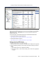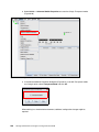
1
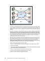
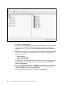
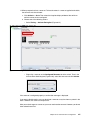
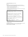
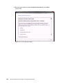
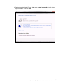
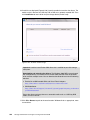
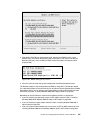
Confirm that the switch name server can detect the WWPN of your CNA and the WWPN of your SAN disk storage. From the name server, some switches can show accessible devices. Make sure that the two devices that you are trying to access communicate and are displayed. Go through the checklist again to ensure that everything is in place on the SAN for the setup to work. Tip: Check the zone, and re-create it. In addition, delete your mapping and remap. When remapped, check the preferred path. These tasks take time, but often correct the error. Then reboot your system and check again if the storage devices are displayed. Hardware does not support boot to disk in UEFI mode In the procedure in 9.6.7, “Booting the Windows DVD in UEFI mode” on page 344, you might receive a message that indicates that the hardware might not support boot to disk. If you see this message, review the setup instructions in 9.6.1, “Configuring an Emulex card for boot from SAN” on page 333, and then check the following settings: Verify that the boot device was added when you pressed F1 (go back and check). Verify that the BIOS is enabled on the Emulex port (go back and check). Verify that the CNA from which you are trying to do the boot is on the preferred path of the SAN disk. The most common cause of an offline disk is that the preferred path is not assigned correctly. Check your SAN disk device configuration, and then reboot the server again on the Windows DVD. Verify that your SAN disk supports a UEFI boot. Verify that your SAN disk is updated to the latest firmware. Try to perform a legacy installation. If you see the disk as being offline, see Windows KB 2345135, “Setup reports error ‘Windows cannot be installed to this disk...’ when booted from DVD” at this website: http://support.microsoft.com/kb/2345135 If Setup reports the error message “Windows cannot be installed to this disk...” booted from DVD in UEFI mode, consider modifying the Windows installation media. Use Windows media that is bundled with the latest service pack. If you see a 20-MB disk, you most likely mapped the access LUN instead of the LUN. To correct this problem, log in to your disk storage subsystem. Verify that your LUN is using LUN 0, which is defined in the SAN disk device. Verify that you are using the latest Windows DVD with the latest service pack built-in. Verify that the path is on the preferred path. Check with your SAN configuration. Verify that zoning is correct or unchanged. Verify that LUN mapping is correct or unchanged. 368 Storage and Network Convergence Using FCoE and iSCSI