1
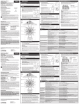
COMPONENTS
BASIC FUNCTIONS
LAMP HOUSING
BEZEL
Control Panel Diagram
CONTROL
PANEL
MOLLE-READY
RETENTION
CLIP
LOCK (RED/GREEN)
INDICATOR
CYCLE CONTROL
CONSTANT-ON
CONTROL
MOMENTARY
CONTROL
FINGER LOOP
BATTERY HOUSING/SLEEVE
Lockout/Ready Mode
STEP 1. Remove battery cap. Insert two batteries “+” terminals first
(as shown above).
Lockout Mode prevents accidental illumination.
To unlock the light and enter Ready Mode,
LOCK (RED/GREEN)
press the Constant-On and
INDICATOR
Cycle Control
buttons simultaneously
and release. The green “unlock” indicator will
CONSTANT-ON
illuminate signaling that visible light modes
CONTROL
are active.
To reenter Lockout Mode at any time during use,
press and hold the Constant-On
and Cycle Control
buttons simultaneously for
1 second. The red “lockout” indicator will illuminate.
STEP 2. Reinstall battery cap. Hand-tighten until snug.
Momentary Mode
I/O
BATTERY CAP
BATTERY INSTALLATION
CYCLE CONTROL
I/O
The Momentary Control
button activates the
primary white LED at maximum brightness when
pressed. When released, the white LED turns off.
(
STEP 3. Ensure batteries are properly installed by pressing any button on the control panel. The red LED “lock” should illuminate indicating the light is in Lockout Mode. If it does not, repeat Steps 1 and 2, ensuring both “+” terminals are facing up.
MOMENTARY
CONTROL
6
7