1
you can still demonstrate all the items listed above. And you can use this circuit as a lead-in to a
follow-up experiment with a circuit that maintains constant frequency as you vary duty-cycle.
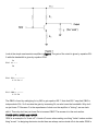
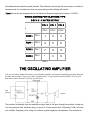
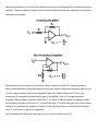
The key to the circuit is the CD4093 CMOS digital IC. It's a quad two-input NAND gate chip with
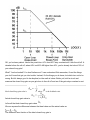
Schmitt-trigger inputs. In an inverting configuration, driving the inputs high will force the output low,
while driving the inputs low will force the output high. The value of the input voltage that causes the
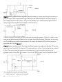
output to change is the switching-threshold. The switching-threshold on a Schmitt-trigger input is not
fixed; it has one of two different values depending on whether the output is high or low. In the 4093,
the input voltage to force the output low is higher than the input voltage that forces the output high
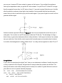
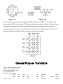
(see Figure 2). The result is a hysteresis effect.
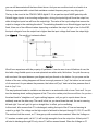
Figure 2
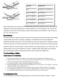
We all have experience with the property of hysteresis. It can be seen in an old-fashion oil-can, the
kind with a long flexible spout on a semi-spherical can with a wide, flat bottom. You pick the can up
with one hand: the spout between your fingers and your thumb on the bottom. As you press on the
bottom of the can, nothing happens until there is enough pressure to "pop" the bottom in and a squirt
of oil comes out. As you release the pressure, the bottom will "pop" back out at less pressure than it
took to "pop" it in.
The way hysteresis leads to oscillation can be seen in an automobile with a loose "front end". As you
turn the steering wheel, nothing happens at first. Then, at a certain point, the car will turn. As you turn
the wheel back to "straighten out", again nothing happens until you get to a point where the car
suddenly swerves the other way. The result is that, as you travel down the road, the car is swerving
left and right. You can't get it to go in a straight line. In effect, you're oscillating.
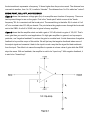
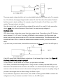
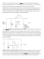
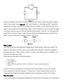
In this circuit, let's assume that C1 is discharged, making the input of the IC low and causing its
output to go high. The voltage on the high output is fed back to the input through R1, R2, D1 and R3.
The resistors limit the current, so C1 charges up with a certain time-constant. When the Voltage on
C1 reaches a certain point, call it V1, it will be high enough to force the output low. At that point C1
will start to discharge through R3 only, since D1 will be reverse-biased. When the Voltage on C1