Download DT9818 Datasheet
Transcript
DT9818
DT9818
Type: Isolated, Embedded
Isolated, Embedded USB
Data Acquisition Module
The DT9818 combines the functionality
of multiple boards in a single USB 2.0
module to provide simultaneous analog
input, analog output, digital I/O, and
counter/timer operations. The DT9818
module features up to 32 single-ended
or 16 differential analog input channels;
depending on the model selected. All
analog input signals are multiplexed to
a single analog-to-digital converter. The
DT9818 supports sampling rates of up
to 150 kSamples/s with 16-bit
resolution. Four programmable gains (1,
2, 4, and 8) are provided to support input signal
ranges of ±10 V, ±5 V, ±2.5 V, and ±1.25 V for
each individual channel.
Bus: USB
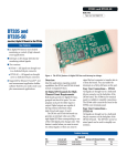
Figure 1. The DT9818 is a high performance, isolated data acquisition module
that can be readily embedded in industrial or laboratory applications. It allows
synchronous or asynchronous operation for all the analog, digital, and
counter/timer functions, while running off USB power.
Key Features:
■
■
■
■
■
■
■
■
Board-level OEM version... embed in custom
applications
500 V galvanic isolation... prevents ground loops,
maximizes analog signal integrity, and protects the
computer
Runs on USB power... ideal for portable applications...
no external power supply needed
Simultaneous operation of analog input, analog output,
digital I/O, and counter/timer subsystems... no
restrictions
16-bit resolution, 150 kHz throughput on both the A/D
and D/A
Up to 32 SE or 16 DI analog input channels
Two deglitched analog outputs for smooth waveform
generation... less than 1.0 nV-sec glitch energy
8 digital input/output lines clocked synchronously at
the analog input/output rate
■
■
■
■
■
■
Two 32-bit counter/timer channels acquired/read
synchronously at the analog input rate
Independent clock sources (internal and external) for
pacing analog inputs and analog outputs
Independent trigger sources (internal and external) for
starting analog input and analog output operations
Flexible acquisition modes (single value, continuous,
and triggered scan) for input operations, and flexible
output modes (single value, continuous, and waveform
generation) for output operations
High-speed USB data at rates up to 480 Mbps
Many software choices available for application
development... from ready-to-measure programs like
Measurement Applets and quickDAQ to full graphical
programming with Measure Foundry®
Figure 2. The 500V galvanic isolation allows
all analog input, analog output, digital I/O,
and counter/timer functions to operate in
high noise environments. Signal accuracy is
maintained despite the presence of large
noise spikes on small signal paths. This is
especially critical for embedded
applications.
WWW.DATATRANSLATION.COM
US/CANADA (800) 525-8528
EUROPE/ASIA +49 (0) 7142-9531–0
Figure 3. The in-depth DT9818 block diagram shows all functions and controls.
For embedded applications, helpful connection panels are available. Figure 4 shows DIN type mass terminations, while Figure
5 shows screw terminal terminations.
Figure 4. This example shows an EP353 accessory panel, which
plugs into connector J2, and an EP356 accessory panel, which plugs
into J3.
WWW.DATATRANSLATION.COM
US/CANADA (800) 525-8528
Figure 5. The EP355 screw terminal panel plugs into the J2 or J3
connector of a DT9818 module.
EUROPE/ASIA +49 (0) 7142-9531–0
2
Uncompromised, High-Integrity Performance
High Throughput...
Fast settling
instrumentation
amplifier maintains highspeed while switching
channels
Clean Signal
Connection...
Up to 32 high-speed
analog input channels
Precision
Measurements...
True 16-bit resolution at
150kHz throughput for
measuring dynamic
signals
Ultra Digital I/O...
Full digital I/O flexibility
for pattern generation
and synchronizing with
external events
Fully Protected...
500V galvanic isolation
protects your computer
and maintains signal
integrity
Full-Featured
Counter/Timers...
Two 32-bit
counter/timers ideal
for automotive testing
applications
No Limits...
Full simultaneous
operation of all
subsystems
Pure Signal
Generation...
Two waveform
deglitched DACs
Designed for
Low Noise...
Multi-layer PCB provides
optimal grounding and
shielding to maintain
signal integrity
External Control...
Flexible clocks and
triggers
Figure 6. DT9818 board-level OEM version can be embedded into custom
applications.
WWW.DATATRANSLATION.COM
US/CANADA (800) 525-8528
EUROPE/ASIA +49 (0) 7142-9531–0
3
Flexible Acquisition Modes... Using The Input Channel-Gain List
The DT9818 module can acquire data from one or more
analog input channels using an input channel-gain list. A
1024-location channel-gain list allows great flexibility in
configuring channels, sample rates, and gains. For example, it
permits sampling non-sequential analog input channels,
analog input channels with different gains, and digital inputs
and counter/timer channels with the analog input channels
at the A/D sample rate.
Table 1: Input Gain-Channel List (CGL) – Example
Channel
List Entry
Channel Gain Operation
0
4
1
AIN4
Read analog input channel 4
using a gain of 1 (input range
±10V).
1
5
2
AIN5
Read analog input channel 5
using a gain of 2 (input range
±5V).
2
4
1
AIN4
Read analog input channel 4
using a gain of 1 (input range
±10V).
3
6
4
AIN6
Read analog input channel 6
using a gain of 4 (input range
±2.5V).
4
16
1
DINa
Read the digital input port.
5
17
1
C/T0b
Read the lower 16-bit word of
counter/timer 0.
6
18
1
C/T0b
Read the upper 16-bit word of
counter/timer 0.
7
19
1
C/T1c
Read the lower 16-bit word of
counter/timer 1.
8
20
1
C/T1c
Read the upper 16-bit word of
counter/timer 1.
.
.
.
.
.
.
.
.
.
.
.
.
1023
0
8
AIN0
All input channels can be entered in the input channel-gain
list (CGL), as shown in Table 1.
For each entry in the input channel-gain list, specify the
channel to sample and the gain to apply to that channel.
Channels in an input channel-gain list are sampled in order
from the first entry to the last entry in the list. Channel
numbering is zero-based; that is, the first entry in the input
channel-gain list is entry 0, the second entry is entry 1, and so
on.
The DT9818 module provides two ways to cycle through the
channel-gain list:
■
■
Continuous scan mode ‒ Choose this mode to
accurately control the period between conversions of
individual channels in the channel-gain list.
Triggered scan mode ‒ Choose this mode to accurately
control both the period between conversions of
individual channels in the channel-gain list and the
period between each scan. This mode emulates a
sample-and-hold function and is useful when
synchronizing or controlling external equipment, or
when acquiring a buffer of data on each trigger. Using
this mode allows acquisitions of up to 262,144 samples
per trigger (256 times per trigger x 1024-location
channel-gain list).
Description
.
.
.
Read analog input channel 0
using a gain of 8 (input range
±1.25V).
a. To read the digital input port, specify channel 16
b. To read C/T0, specify channel 17 to read the lower 16-bit word and channel 18 to read
the upper 16-bit word of the 32-bit counter.
c. To read C/T1, specify channel 19 to read the lower 16-bit word and channel 20 to read
the upper 16-bit word of the 32-bit counter.
On each pulse of the sample clock, the corresponding
input CGL entry is read.
In triggered scan mode, the period between
scans is determined by the trigger.
Figure 7. Timing Diagram for Continuous Input and Triggered Scan Operations.
WWW.DATATRANSLATION.COM
US/CANADA (800) 525-8528
EUROPE/ASIA +49 (0) 7142-9531–0
4
Flexible Output Modes... Using The Output Channel-Gain List
The DT9818 module provides a great deal of flexibility in the
output of analog and digital signals. For example, output a
single value from a single analog output channel or multiple
values from multiple analog output channels. An outputchannel list gives the flexibility of updating only the analog
output channels desired or updating the digital output lines
with specified analog output channels at the D/A clock rate.
Analog output channels can be updated at up to 150
kSamples/s.
The DT9818 module features the following output modes:
All output channels can be entered in the output channelgain list (CGL), as shown in Table 2. The output channel-gain
list is fixed at 3 entries.
Using software, specify the values to output to each channel
using a buffer of up to 16K bytes. Figure 8 shows the timing
diagrams for continuous output and waveform operations.
■
■
Continuous output mode ‒ Choose this mode to
accurately control the period between conversions of
individual output channels in the output-channel list.
Waveform mode ‒ Choose this mode to output
waveforms repetitively from an output FIFO on the
module. Using waveform mode, multiple channels can
be updated at up to 150 kSamples/s.
Table 2: Output Channel-Gain List – Example
Channel List
Entry
Channel Gain
Operation
Description
0
0
1
DAC 0
Update DAC 0.
1
1
1
DAC 1
Update DAC 1.
2
2
1
Digital
Updated the digital output
Output Porta port.
a. To update the digital output port, specify channel 2.
The channels in the output CGL are updated simultaneously with the values from
specific locations in the output buffer. For example, the values from buffer
locations 0, 3, 6, and 9 are written to DAC0, the values from buffer locations 1, 4, 7,
and 10 are written to DAC1, and the values from buffer locations 2, 5, 8, and 11 are
written to the digital output port.
Figure 8. Timing Diagram for Continuous Output and Waveform Generation Operations.
WWW.DATATRANSLATION.COM
US/CANADA (800) 525-8528
EUROPE/ASIA +49 (0) 7142-9531–0
5
DT9818-32-STP
STP Connection Box
Analog Input
Connections
Figure 9. The DT9818 is also available in a BNC boxed version that
houses the DT9818-OEM board. This model is useful for OEM
prototypes and end-user applications. Models are: DT9818-16SE-BNC
for a single-ended analog input configuration, and the DT9818-8DIBNC for differential inputs.
High-Speed, High-Resolution Analog Outputs
The DT9818 module provides two streaming analog output
channels. Each analog output channel has its own digital-toanalog converter and provides an output signal range of ±10
V. A maximum update rate of 150 kSamples/second with 16bit resolution is standard. Ultra-smooth waveforms can be
produced with less than 1.0 nV-sec glitch energy from the
D/As. For gap-free simultaneous stimulus and response, the
analog output channels can be updated as the analog input
data is acquired. In addition, you can update the digital
output lines with the analog output channels at the analog
output rate.
High-Speed Digital I/O Lines
DT9818 module features one digital input port, consisting of
8 digital input lines and one digital output port, consisting of
8 digital output lines. The resolution is fixed at 8-bits.
The following digital I/O operation modes are available:
■
Single-value operations are the simplest to use but
offer the least flexibility and efficiency. Use software to
specify the digital I/O port and a gain of 1 (the gain is
ignored). Data is then read from or written to all the
digital I/O lines. For a single-value operation, a clock or
trigger source cannot be specified. Single-value
operations stop automatically when finished.
WWW.DATATRANSLATION.COM
US/CANADA (800) 525-8528
Digital I/O Connections
External Clock and
Trigger Connections
Counter/Timer
Connections
Figure 10. The DT9818-32-STP is an STP boxed version allowing
access to all I/O connections through screw terminals.
■
Continuous digital I/O takes full advantage of the
capabilities of the DT9818 module. Simply specify a
clock source, scan mode, trigger source, buffer, and
buffer wrap mode for the operation.
□ Digital input ‒ For digital input operations, enter the
digital input port (all 8 digital input lines) as channel
16 in the input channel-gain list. The input sample
clock (internal or external) paces the reading of the
digital input port (as well as the acquisition of the
analog input and counter/timer channels).
□ Digital output ‒ For digital output operations, enter
the digital output port (all 8 digital output lines) as
channel 2 in the output channel-gain list. The
output clock (internal or external) paces the update
of the digital output port (as well as the update of
the analog output channels).
Multifunction Counter/Timers
The DT9818 module features two 32-bit user counter/timers.
If desired, read the value of the counter/timer channels with
the analog input channels and digital input lines at the A/D
clock rate. The following counter/timer functions are
supported: event counting, up/down counting, frequency
measurement, edge-to-edge measurement, continuous
edge-to-edge measurement (for determining the frequency
and period width of a signal), rate generation, one-shot, and
repetitive one-shot operations. To read the period of a signal
as part of the analog input data stream, use continuous edgeto-edge measurement mode. Programmable gates, clocks,
and output signals are also supported.
EUROPE/ASIA +49 (0) 7142-9531–0
6
ENOB... The Accuracy Figure of Merit...
USB 2.0 Compatibility
The DT9818 module is fully compatible with USB 2.0 and USB
1.1. USB 2.0 extends the speed of connection to up to 480
Mbps. For optimal performance, it is recommended that you
use the DT9818 module with a USB 2.0 port. The DT9818
Series can be used with a USB 1.1 port, but at USB 1.1
performance. The DT9818 is a complete high speed,
16-bit data acquisition system that runs on USB power only.
No special power requirements.
±10V signal
500 V Galvanic Isolation Protects Your Data
100dB SFDR (Spurious Free Dynamic Range)
14.3 ENOB (Effective Number of Bits)
Computers are susceptible to ground-spikes through any
external port. These spikes can cause system crashes and may
even cause permanent damage to the computer. The DT9818
module features 500 Volts of galvanic isolation to protect the
computer from ground-spikes and to ensure a reliable stream
of data.
Noise Floor
Figure 11. The ENOB program has a 1kHz sine wave on channel 0
with a signal level 0.06db below full scale and channel 1 is tied to
ground or zero volts. (Full scale is 10V). The program is scanning
both channels at a 150kHz rate. The actual sampling rate of channel
0 would then be 75kHz for a Nyquist Frequency of 37.5kHz as shown
in the graph for channel 0. An FFT is computed on channel zero and
displayed. The signal to noise plus distortion is 87.75dB for an
Effective Number of Bits of 14.3. The primary component on the left
side of the chart is the DC component of the signal.
Flexible Clocks and Triggers
For maximum flexibility, the DT9818 module provides
independent clocks and triggers for the A/D and D/A
subsystems. This allows the analog output subsystem to be
triggered and clocked synchronously with, or independent of,
the analog input subsystem. Each subsystem supports an
internal clock and external clock input, as well as the
following trigger types: software command and external
digital input trigger.
WWW.DATATRANSLATION.COM
US/CANADA (800) 525-8528
EUROPE/ASIA +49 (0) 7142-9531–0
7
Cross-Series Compatibility Saves Programming
Time, Protects Your Investment
Virtually all Data Translation data acquisition modules,
including the DT9818, are compatible with the DT-Open
Layers® software standard. This means any application
developed with one of Data Translationʼs software products,
can easily be upgraded to a new Data Translation module.
Little or no reprogramming is needed. For example,
upgrading a DT3016 board on a PCI bus to a DT9818 module
on the USB bus is simple ‒ just load and configure the new
driver.
Software Options
There are many software choices available for application
development, from ready-to-measure applications to
programming environments.
The following software is available for use with the DT9818
module and is provided on the Data Acquisition Omni CD:
■
■
■
■
■
■
DT9818 Device Driver ‒ The device driver allows the use
of a DT9818 module with any of the supported software
packages or utilities.
Measure Foundry® ‒ An evaluation version of this
software is included on the Data Acquisition Omni CD.
Measure Foundry® is a drag-and-drop test and
measurement application builder designed to give top
performance with ease-of-use development.
Measurement Applets ‒ Included in the Measure
Foundry evaluation version. These small applications,
developed with Measure Foundry, can be modified or
combined to provide a specific solution. Order the full
development version of Measure Foundry to develop
applications using real hardware.
quickDAQ application ‒ An evaluation version of this
.NET application is included on the Data Acquisition
Omni CD. quickDAQ acquires analog data from all
devices supported by DT-Open Layers for .NET software
at high speed, plots it during acquisition, analyzes it,
and/or saves it to disk for later analysis.
Quick DataAcq application ‒ The Quick DataAcq
application provides a quick way to get up and running
using a DT9818 module. Using this application, verify
key features of the module, display data on the screen,
and save data to disk.
DT-Open Layers® for .NET Class Library ‒ Use this class
library if you want to use Visual C#® or Visual Basic® for
.NET to develop application software for a DT9818
module using Visual Studio® 2003/2005/2008; the class
library complies with the DT-Open Layers standard.
WWW.DATATRANSLATION.COM
US/CANADA (800) 525-8528
Figure 12. The data recorder applet is developed with Measure
Foundry and allows you to acquire data, plot it, and save it to disk.
Figure 13. quickDAQ acquires analog data from all devices
supported by DT-Open Layers for .NET software at high speed, plots
it during acquisition, analyzes it, and/or saves it to disk for later
analysis.
■
DataAcq SDK ‒ Use the Data Acq SDK to use Visual
Studio 6.0 and Microsoft® C or C++ to develop
application software for a DT9818 module using
Windows®; the DataAcq SDK complies with the DT-Open
Layers standard.
EUROPE/ASIA +49 (0) 7142-9531–0
8
■
■
■
DTx-EZ ‒ DTx-EZ provides ActiveX® controls, which allows access to the
capabilities of the DT9818 module using Microsoft Visual Basic or Visual
C++®; DTx-EZ complies with the DT-Open Layers standard.
DAQ Adaptor for MATLAB ‒ Data Translationʼs DAQ Adaptor provides an
interface between the MATLAB® Data Acquisition (DAQ) toolbox from The
MathWorks™ and Data Translationʼs DT-Open Layers architecture.
LV-Link ‒ An evaluation version of this software is included on the Data
Acquisition Omni CD. Use LV-Link to use the LabVIEW™ graphical
programming language to access the capabilities of the DT9818 module.
User Manual
The DT9818 module includes a userʼs manual that provides getting started and
reference information about using the DT9818. The manual is provided in
electronic (PDF) format on the Data Acquisition Omni CD provided with the
module.
Technical Support
Application engineers are available by phone and email during normal business
hours to discuss your application requirements. Extensive product information,
including drivers, example code, pinouts, a searchable Knowledge Base, and
much more, is available 24 hours a day on our web site at
www.datatranslation.com.
Ordering Summary
Hardware:
■
DT9818-OEM
■
DT9818-8DI-BNC
■
DT9818-16SE-BNC
■
DT9818-32-OEM
■
DT9818-32-STP
Software:
■
Measure Foundry (SP1300-CD)
■
quickDAQ (SP8051-CD)
■
LV-Link (SP0811-CD)
Accessories:
■
EP333 – 2-meter shielded cable for the
EP356 and STP37
■
EP353 – Accessory panel with one
37-pin connector and one 27-pin
connector
■
EP355 – Screw terminal panel
■
EP356 – Accessory panel with two 37pin, D-sub connectors
■
EP360 – 2-meter shielded cable for the
EP353 and STP37
■
STP37 – Screw terminal panel
Accessories for OEM Configurations
For applications where the DT9818 module is embedded in other equipment,
the following optional accessories are available:
■
■
■
■
■
■
EP353 ‒ This accessory panel plugs into connector J2 of a DT9818 module
and provides one 37-pin, D-sub connector and one 26-pin connector for
attaching analog input signals (see Figure 4).
EP355 ‒ This screw terminal panel plugs into connector J2 or J3 of a
DT9818 module and provides 14-position screw terminal blocks for
attaching analog I/O and digital I/O signals. (See Figure 5).
EP356 ‒ This accessory panel plugs into connector J3 of a DT9818 module
and provides two 37-pin, D-sub connectors. You can use one of these
connectors to attach analog output, counter/timer, trigger, and clock
signals, and the other connector to attach digital I/O signals. (See Figure 4
on page 2).
STP37 ‒ This screw terminal panel allows you to connect analog input,
digital I/O, analog output, counter/timer, and clock/trigger signals from the
EP353 or EP356 screw terminal panel.
EP333 ‒ 2-meter shielded cable with two 37-pin connectors that connect
an EP356 accessory panel to an STP37 screw terminal panel.
EP360 - 2-meter shielded cable with two 37-pin connectors that connect an
EP353 accessory panel to an STP37 screw terminal panel.
All Data Translation hardware products are
covered by a 1-year warranty. For pricing
information, see the current price list, visit
our website, or contact your local reseller.
For more information about the DT9818, please visit:
http://www.datatranslation.com/go/dt9818/
For specifications, drawings, and pin assignments, please visit:
http://www.datatranslation.com/go/dt9818/techinfo/
Copyright © 2009 Data Translation, Inc. All rights reserved. All trademarks are the property of their respective holders.
Prices, availability, and specifications are subject to change without notice. Rev 1.2A.
WWW.DATATRANSLATION.COM
US/CANADA (800) 525-8528
EUROPE/ASIA +49 (0) 7142-9531–0


