1
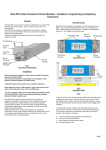
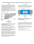
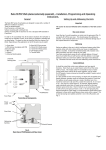
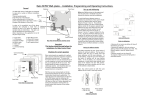
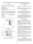
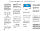
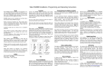
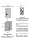
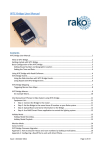
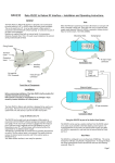
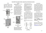
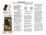
RDC300
12.5A Low Voltage Dimmer Module – Installation and Operating Instructions.
General
Maximum loadings
The Rako RDC300 dimmer module is a low voltage dimmer designed to
work from 24V and 12V dc power supplies. The output is pulse width
modulated and is suitable for low voltage loads.
The dimmer module is designed to be installed in a lighting circuit and is
controlled from the range of Rako transmitting devices including the wall
control panels and hand held units using Rakom encoded radio signals.
Modules are supplied as standard with an external aerial. Units are
available with internally mounted aerials by special order. Modules with
internal aerials are designed for in-line mounting, particularly useful with
free-standing and table lamps. External aerials offer a better reception
range.
300W at 24V DC
150W at 12V DC
Clamping bar
BYPASS
Mounting Holes
Fixing Screws
Terminal
Cover
Connection
Terminal
Set-up
Connector
Fig 2.
Termination Area
Protective
Insert
Supply/Load
Terminals
Dimmer
Housing
+V
0V
BYPASS
Set-up
Connector
Fig 1.
Front View of Components
BYPASS
SWITCH
Installation
LOAD
Before commencing installation of a Rako dimmer module first read this
instruction manual carefully.
Rako Controls Ltd accepts no responsibility for any damage or injury
caused by incorrect installation of a Rako product.
+
Fig 3.
Connection Detail
Installation should only be carried out by a competent electrician.
Never attempt to connect a Rako dimmer or remove the terminal covers
without first isolating the circuit at the fuse/MCB board.
The circuit supplying a Rako dimmer should always be protected by a
suitably rated fuse.
Rako RDC300 dimmer module should be mounted in areas that are
adequately ventilated, dry and outside of any enclosed metal casings.
Wherever possible the modules should be securely fixed using the
mounting holes provided. The mounting holes are blanked off when
supplied but are designed so that a woodscrew will easily cut through
without the need for drilling.
Whilst the Rako dimmer modules are designed to be completely
maintenance free the units should be mounted in a position where access
can be gained should there be a fault or re-addressing of the unit be
necessary (see ‘Set-up and Addressing’).
Note:
To ensure that the cable clamping operates satisfactorily the cabling both
supplying the dimmer and to the load should be a minimum of 0.5mm
with double safety insulation and the wires should be stripped to ensure
that the cable bar within the terminal cover clamps firmly on both sets of
insulation.
2
To install a Rako dimmer module isolate the supply then remove the
Terminal Covers (see Fig.1) giving access to the supply/load terminals.
The necessary connections are indicated on the label on the dimmer
housing. The notation is as follows:
Supply +
Supply 0V
+ve DC input
0v DC input
Important : The polarity of the supply must not be reversed.
Load +
Load –
+ve dimmed output
-ve dimmed output
Bypass
Connects the supply directly to the output via the
20Amp internal fuse.
Page 1
Installation (continued)
Set-up and Addressing
Once the supply and load cables are connected ensure that the terminal
covers are replaced and securely fastened, clamping the cable correctly as
detailed above, before powering the unit.
Before a Rako dimmer module will work with a Rako scene-sender control
panel it must first receive an address identity from the control panel. To
do this follow the set-up and addressing procedure as detailed below.
Rako dimmer modules are not designed for loop in/loop out connections.
Should it be necessary to loop the supply on to further fittings then a
junction box should be connected in circuit to facilitate this.
Setting an address is the way in which interference between other Rako
systems, either with other rooms within your house or neighbouring
houses is avoided. It should be remembered that with a booster unit a
Rako transmitter may have a range of over 100m.
With the supply and load connected and prior to switching on the supply
ensure that the terminal covers are fitted and that they are securely
clamping the cables. It is important to ensure that the protective inserts
(see Fig.1) are fitted and located securely, both in the terminal cover and
over the supply and load cables. The protective inserts provide important
protection against the risk of electric shock from conductive objects
forced down the side of the cables.
Your Rako control panel comes set with a default address of House 1,
Room 4, Channel 1 and whilst the unit will function with this address it is
strongly advised to select your own house address and logical room
addresses. Fig. 4 illustrates how the house and room addressing avoids
interference.
It should be noted that certain room addresses can have special
functions. A panel set as Room 0 acts as an overall master control for all
the rooms within a house. This maybe useful if it is desirable to have a
master control panel which controls all the rooms together, say for master
On/Off panels at main entrances but should be avoided if master control
is not intended. It is only possible to give panels the address of Room 0
and not receivers as a panel set to Room 0 will control all receivers in a
house anyway.
When power is connected the Rako unit will fade to a full-on setting. In
this way it is possible to leave a conventional lighting switch in circuit to
simply fade between full-on and off settings without the use of a Rako
control panel. Such a lighting switch can also be used as an override in
the event that the batteries in a Rako control panel are not replaced
when the low-battery warning signals indicate that this should be done.
It is also possible to have room grouping, see Fig.5 (only accessible using
Rasoft software), whereby rooms are clustered into groups of 4 with the
first address in each group acting as a master, therefore room 5 is a
master for rooms 6,7, & 8, room 9 is a master for rooms 10, 11 & 12 and
so on. This may be a useful feature if, for example, bedside lighting
needs individual control but still needs to be turned off at the main
bedroom panel at the door. Room 0 still acts as an overall house master
as well as for its own group of rooms 1,2 & 3. As room grouping may
become desirable at a later stage it is recommended to avoid setting room
addresses to those which would become slave rooms within a group. This
is done by leaving room address switches 1 & 2 in the off position, see
Fig. 6.
House XXX
House XXY
Room 0
Room 0
Room 0 Has overall control
of all rooms in the house
House XXX
Room 0
Room 0. Overall control
Room 0 Has overall control
of all rooms in the house
Room AAA
Room AAA
Individual Room Control
Room AAB
Individual Room Control
No Interference
between rooms
with different
addresses
No Interference
between houses
with different
addresses
Room AAA
Individual Room Control
Fig 4.
Rako house and room addressing
Room AAB
Individual Room Control
No Interference
between rooms
with different
addresses
Room AAB
Group master. Controls
all rooms within group
Group master. Controls
all rooms within group
Room
AAA+1
AAB+1
Room
AAB+1
Room
AAA+3
AAB+1
Room
AAA+2
AAB+1
No interference
between rooms
within a group
Room
AAB+3
Room
AAB+2
Fig 5.
Rako addressing with grouping enabled.
Page 2
Receiver modules not only have house and room addresses but also a
channel address, which can be set from 1-15 for each room. This channel
address is what allows different circuits to be set at different levels for
each scene. Setting all of these addresses is achieved by a single
command from a wall-plate in programming mode.
The procedure for setting the receiver address is as follows. See the
relevant section for details on each step.
House address
= 128+16=144
•
•
•
•
•
•
ROOM
128
64
32
16
8
4
2
1
ON
ON
128
64
32
16
8
4
2
1
BINARY VALUE
Each Rako transmitter has two, 8 way banks of switches for setting its
address. The two sets of switches allow the user to choose from 256
house addresses and 256 room addresses (64 groups of 4 with grouping
enabled). To set the address, unclip the rear cover whereupon the banks
of switches will be now become visible. To set an address, use a small
terminal screwdriver or similar device and carefully move some of the
switches into the ‘ON’ position. Addressing uses binary encoding and the
value of the switches is shown below.
HOUSE
Setting receiver addresses.
BINARY VALUE
Setting an Address
ROOM BECOMES A SLAVE ROOM
WITH EITHER OF THESE SWITCHES
SET ON AND GROUPING ENABLED
Room address
= 32+4=36.
Fig 6.
Addressing Switches
Once the addresses have been set it is strongly recommended to keep a
note of the settings and to keep these in safe place. Whilst it is easy to
set the addresses, those of the receiver units are normally only set once.
To do so requires access to the units and once set these may be installed
in inaccessible positions. If, therefore the wall-plate address get changed
for any reason and the original settings cannot be remembered then
access to the receiver units will be needed for reconfiguration.
Note:
Put wall-plate into programming mode.
Find an available channel.
Put receiver into set–up mode.
Press the ident button.
Exit programming mode on wall-plate.
Exit set-up mode on receiver (done automatically when using
the magnet method).
Putting Wall-plate into programming mode.
Press and hold a scene button (one of the four numbered buttons on the
left hand side of the plate) and at the same time press and hold both the
raise and lower buttons (the right hand buttons). After 3 seconds the
LED will start to flash, the plate is now in programming mode. To exit
programming mode press the Exit button (see Fig. 8).
Note:
If the Exit button is not pressed or any other buttons pressed the panel
will exit from programming mode automatically after 3 minutes.
LED indicator
Scene buttons
Once the address for a control panel has been set the transmitter, or at
least one transmitter within a room, needs to send its address to all the
receiver modules that it needs to control. This can either be done before
or once the control panel has been installed.
Master raise and
lower buttons
Fig 7.
Wall-plate buttons in normal mode
Channel
scroll up
Level up
Channel
scroll down
Ident
Level down
Store
Exit
Fig 8.
Wall-plate buttons in programming mode
Page 3
Setting a receiver’s address.
Note:
The first step is to find an available channel address for the receiver. For
convenience, this is usually the next available channel after all the already
allocated addresses. To identify which channels already have allocated
addresses first put the wall-plate into programming mode. Then, using
the Channel scroll up and Channel scroll down keys scroll through the 15
available channel addresses. When a channel address is reached which
already has a receiver allocated, that receiver will flash its load in a slow
double pulse to identify itself. Channel 0 will flash all the channels in a
fast quadruple flash indicating the start point (note: it is not possible to
program a receiver to channel 0. Scroll through until you find an
available channel i.e. a channel where no load flashes, or to another
specific channel that you wish to set the receiver to and then stop. This
is the channel identity that will be sent to the receiver when the Ident key
is pressed. Next put the receiver into set-up mode (see putting receiver
into set-up mode) and then press the Ident button. The receiver will
flash its load to acknowledge receipt of the command and then
automatically drop out of set-up mode (unless using the header
connector method, see notes). The receiver has now registered the
house, room and the specific channel address that it should respond to.
If no more set-up commands are to be sent by the wall-plate then press
the Exit key to return the panel to normal operating mode.
If no commands are received from the wall-plate within 3 minutes the
receiver will automatically come out of set-up mode. The receiver will
also come out of programming mode if the power to the unit is
interrupted.
Note:
For ease of use it is generally advisable to set the channel addresses in a
sequence from channel 1 onwards.
It is possible to set two receivers to the same channel address. This has
been deliberately made possible, as it may be desirable to have two
receivers that always respond together fading to exactly the same lighting
levels. For example there may be two identical up-lighters, both fed from
independent receivers, which need to always respond as one.
Programming a lighting scene.
To program a scene firstly choose which scene is to be programmed or reprogrammed. Press and hold that scene button and at the same time
press and hold both the master raise and lower buttons. After 3 seconds
the panel will go into programming mode and the LED will start to flash.
Next, using what are now the Channel scroll up and down buttons, scroll
through to a channel whose level needs to be altered. As the channels
are scrolled through they will each, in turn, flash their loads to indicate
which is the current channel. At any time pressing the ident button will
flash the currently selected channel without scrolling on. When the
appropriate channel has been reached use the channel raise lower
buttons to alter the lighting level for that load. Scroll through the
remaining channels changing the lighting levels until the desired scene
has been set. Pressing the store button will save all current levels to that
scene and all the receivers should now flash their load again to confirm
that the levels have been stored. Press the Exit key to return the Wallplate to normal mode.
Note: When re-programming a lighting scene it is quite possible to enter
programming mode, select and alter only one or two channels and re-set
their levels without adjusting any of the remaining channels. Thus fine
tuning a scene becomes a simple and easy task.
Care and maintenance
Putting the Receiver into set –up mode.
Firstly ensure that the receiver has been connected correctly, that the
unit is powered up and that a suitable lighting load is connected.
Using the small magnet provided with each receiver, press the magnet
against the receiver casing just over halfway down (see Fig.9). The
approximate position for this is indicated by the ‘magnet point’ legend on
the top label. When the magnet is in the correct position an internal LED
will illuminate. The LED will stay on with a steady illumination all the
time that the magnet is in the correct position. Hold the magnet in this
position for 3 seconds until the LED starts to flash. The receiver is now in
set up mode.
General
Rako thanks you for having purchased a Rako product and hopes that
you are pleased with your system. Should for any reason you need to
contact us please contact us via our website www.rakocontrols.com or by
phoning our customer help line on 0870-043-3905.
Magnet
Approximate position for Rako
programming magnet.
Fig 9.
Set-up Magnet Positioning
Page 4