1
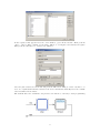
Turbo Chameleon 64
The Core Developers Manual
Peter Wendrich
[email protected]
May 30, 2013
Draft version!
Contents
1 Introducing the Turbo Chameleon 64
1.1 Reconfigurable hardware . . . . . . . . . . . . . . . . . . . . . . . . . . . . . . . . .
1.2 This document . . . . . . . . . . . . . . . . . . . . . . . . . . . . . . . . . . . . . .
2
2
3
2 JTAG
2.1 JTAG Boundary Scan . . . . . . . . . . . . . . . . . . . . . . . . . . . . . . . . . .
2.2 Loading a design through JTAG . . . . . . . . . . . . . . . . . . . . . . . . . . . .
3
3
5
3 I/O
3.1
3.2
3.3
3.4
3.5
3.6
3.7
3.8
3.9
3.10
3.11
3.12
3.13
mux
FPGA and MUX communication
DMA . . . . . . . . . . . . . . .
R/W . . . . . . . . . . . . . . . .
NMI, IRQ . . . . . . . . . . . . .
EXROM, GAME . . . . . . . . .
IOW and IOR . . . . . . . . . . .
Flash-ROM CS . . . . . . . . . .
RTC CS . . . . . . . . . . . . . .
MMC CS . . . . . . . . . . . . .
SPI MOSI, SPI CLK . . . . . . .
LEDs . . . . . . . . . . . . . . .
IEC . . . . . . . . . . . . . . . .
PS/2 . . . . . . . . . . . . . . . .
4 FPGA I/O lines
4.1 IOe and IOf . .
4.2 ROML and ROMH
4.3 Phi-2 . . . . . .
4.4 Dot-Clock . . .
5 C64
5.1
5.2
5.3
5.4
5.5
.
.
.
.
.
.
.
.
.
.
.
.
.
.
.
.
.
.
.
.
.
.
.
.
.
.
.
.
.
.
.
.
.
.
.
.
.
.
.
.
.
.
.
.
.
.
.
.
.
.
.
.
.
.
.
.
.
.
.
.
.
.
.
.
.
.
.
.
.
.
.
.
.
.
.
.
.
.
.
.
.
.
.
.
.
.
.
.
.
.
.
.
.
.
.
.
.
.
.
.
.
.
.
.
.
.
.
.
.
.
.
.
.
.
.
.
.
.
.
.
.
.
.
.
.
.
.
.
.
.
.
.
.
.
.
.
.
.
.
.
.
.
.
.
.
.
.
.
.
.
.
.
.
.
.
.
.
.
.
.
.
.
.
.
.
.
.
.
.
.
.
.
.
.
.
.
.
.
.
.
.
.
.
.
.
.
.
.
.
.
.
.
.
.
.
.
.
.
.
.
.
.
.
.
.
.
.
.
.
.
.
.
.
.
.
.
.
.
.
.
.
.
.
.
.
.
.
.
.
.
.
.
.
.
.
.
.
.
.
.
.
.
.
.
.
.
.
.
.
.
.
.
.
.
.
.
.
.
.
.
.
.
.
.
.
.
.
.
.
.
.
.
.
.
.
.
.
.
.
.
.
.
.
.
.
.
.
.
.
.
.
.
.
.
.
.
.
.
.
.
.
.
.
.
.
.
.
.
.
.
.
.
.
.
.
.
.
.
.
.
.
.
.
.
.
.
.
.
.
.
.
.
.
.
.
.
.
.
.
.
.
.
.
.
.
.
.
.
.
.
.
.
.
.
.
.
.
.
.
.
.
.
.
.
5
5
6
6
6
6
6
6
7
7
7
7
7
7
.
.
.
.
.
.
.
.
.
.
.
.
.
.
.
.
.
.
.
.
.
.
.
.
.
.
.
.
.
.
.
.
.
.
.
.
.
.
.
.
.
.
.
.
.
.
.
.
.
.
.
.
.
.
.
.
.
.
.
.
.
.
.
.
.
.
.
.
.
.
.
.
.
.
.
.
.
.
.
.
.
.
.
.
.
.
.
.
.
.
.
.
.
.
.
.
.
.
.
.
.
.
.
.
.
.
.
.
.
.
.
.
.
.
.
.
.
.
.
.
7
8
8
8
8
Expansion Bus
PHI2 and BA . . . . . . . . . .
Implementing ROM cartridges
Implementing I/O registers . .
DMA and external CPUs . . .
Feeding VIC-II . . . . . . . . .
.
.
.
.
.
.
.
.
.
.
.
.
.
.
.
.
.
.
.
.
.
.
.
.
.
.
.
.
.
.
.
.
.
.
.
.
.
.
.
.
.
.
.
.
.
.
.
.
.
.
.
.
.
.
.
.
.
.
.
.
.
.
.
.
.
.
.
.
.
.
.
.
.
.
.
.
.
.
.
.
.
.
.
.
.
.
.
.
.
.
.
.
.
.
.
.
.
.
.
.
.
.
.
.
.
.
.
.
.
.
.
.
.
.
.
.
.
.
.
.
.
.
.
.
.
.
.
.
.
.
.
.
.
.
.
.
.
.
.
.
.
.
.
.
.
8
8
9
9
10
10
.
.
.
.
.
.
.
.
.
.
.
.
.
.
.
.
.
.
.
.
.
.
.
.
.
.
.
.
.
.
.
.
6 Clockport
11
1
7 USB Debug interface
7.1 Commands from USB to FPGA . . . . . . . . . . . . . . . . . . . . . . . . . . . . .
7.2 Commands from FPGA to USB . . . . . . . . . . . . . . . . . . . . . . . . . . . . .
12
12
12
8 Boot Flash
12
9 PS/2 Keyboard and Mouse
9.1 PS/2 protocol . . . . . . . . . . .
9.2 Using a PS/2 keyboard . . . . .
9.2.1 PS/2 keyboard typematic
9.2.2 PS/2 keyboard scan-codes
9.3 Using a PS/2 mouse . . . . . . .
9.3.1 Mouse status packet . . .
9.3.2 Mouse movement packet .
.
.
.
.
.
.
.
.
.
.
.
.
.
.
.
.
.
.
.
.
.
.
.
.
.
.
.
.
.
.
.
.
.
.
.
.
.
.
.
.
.
.
.
.
.
.
.
.
.
.
.
.
.
.
.
.
.
.
.
.
.
.
.
.
.
.
.
.
.
.
.
.
.
.
.
.
.
.
.
.
.
.
.
.
.
.
.
.
.
.
.
.
.
.
.
.
.
.
.
.
.
.
.
.
.
.
.
.
.
.
.
.
.
.
.
.
.
.
.
.
.
.
.
.
.
.
.
.
.
.
.
.
.
.
.
.
.
.
.
.
.
.
.
.
.
.
.
.
.
.
.
.
.
.
.
.
.
.
.
.
.
.
.
.
.
.
.
.
.
.
.
.
.
.
.
.
.
.
.
.
.
.
.
.
.
.
.
.
.
.
.
.
.
.
.
.
13
13
13
14
14
15
16
16
10 IR (CDTV remote)
10.1 IR protocol . . . .
10.2 Pulse/Pause coding
10.3 Key codes . . . . .
10.4 Mouse/Joy codes .
.
.
.
.
.
.
.
.
.
.
.
.
.
.
.
.
.
.
.
.
.
.
.
.
.
.
.
.
.
.
.
.
.
.
.
.
.
.
.
.
.
.
.
.
.
.
.
.
.
.
.
.
.
.
.
.
.
.
.
.
.
.
.
.
.
.
.
.
.
.
.
.
.
.
.
.
.
.
.
.
.
.
.
.
.
.
.
.
.
.
.
.
.
.
.
.
.
.
.
.
.
.
.
.
.
.
.
.
.
.
.
.
17
17
17
17
18
11 Docking Station
11.1 Protocol . . . . . . . . . . . . . . . . . . . . . . . . . . . . . . . . . . . . . . . . . .
11.2 Amiga keyboard LEDs . . . . . . . . . . . . . . . . . . . . . . . . . . . . . . . . . .
11.3 Example code . . . . . . . . . . . . . . . . . . . . . . . . . . . . . . . . . . . . . . .
18
19
20
21
12 Using SDRAM
12.1 Rows and banks . . . . . . .
12.2 SDRAM commands . . . . .
12.3 SDRAM performing accesses
12.4 SDRAM refresh . . . . . . . .
12.4.1 SDRAM timing . . . .
12.4.2 CAS Latency . . . . .
12.4.3 Burst . . . . . . . . .
12.4.4 Byte accesses . . . . .
12.5 SDRAM clocking . . . . . . .
12.6 SDRAM initialization . . . .
12.6.1 Initialization sequence
12.6.2 Mode Register . . . .
21
21
21
22
22
22
22
22
22
23
23
23
23
.
.
.
.
.
.
.
.
.
.
.
.
.
.
.
.
.
.
.
.
.
.
.
.
.
.
.
.
.
.
.
.
.
.
.
.
.
.
.
.
.
.
.
.
.
.
.
.
.
.
.
.
.
.
.
.
.
.
.
.
.
.
.
.
.
.
.
.
.
.
.
.
.
.
.
.
.
.
.
.
.
.
.
.
.
.
.
.
.
.
.
.
.
.
.
.
.
.
.
.
.
.
.
.
.
.
.
.
.
.
.
.
.
.
.
.
.
.
.
.
.
.
.
.
.
.
.
.
.
.
.
.
.
.
.
.
.
.
.
.
.
.
.
.
.
.
.
.
.
.
.
.
.
.
.
.
.
.
.
.
.
.
.
.
.
.
.
.
.
.
.
.
.
.
.
.
.
.
.
.
.
.
.
.
.
.
.
.
.
.
.
.
.
.
.
.
.
.
.
.
.
.
.
.
.
.
.
.
.
.
.
.
13 Pins and Signals
1
.
.
.
.
.
.
.
.
.
.
.
.
.
.
.
.
.
.
.
.
.
.
.
.
.
.
.
.
.
.
.
.
.
.
.
.
.
.
.
.
.
.
.
.
.
.
.
.
.
.
.
.
.
.
.
.
.
.
.
.
.
.
.
.
.
.
.
.
.
.
.
.
.
.
.
.
.
.
.
.
.
.
.
.
.
.
.
.
.
.
.
.
.
.
.
.
.
.
.
.
.
.
.
.
.
.
.
.
.
.
.
.
.
.
.
.
.
.
.
.
.
.
.
.
.
.
.
.
.
.
.
.
.
.
.
.
.
.
.
.
.
.
.
.
.
.
.
.
.
.
.
.
.
.
.
.
.
.
.
.
.
.
.
.
.
.
.
.
.
.
.
.
.
.
.
.
.
.
.
.
24
Introducing the Turbo Chameleon 64
The ”Turbo Chameleon 64” is a multi-function expansion cartridge for the Commodore-64 home
computer. The name is based on the multiple function aspects of the cartridge: VGA video,
mass-storage, freezer and turbo. It can also emulate many classic cartridges, while providing the
new functions at the same time. Some of the cartridges emulated are freezers, speeders, games
and memory expansions. Finally it has a drive subsystem that emulates a complete 1541 diskdrive
on a hardware level.
1.1
Reconfigurable hardware
A Cyclone III FPGA chip powers most of the logic functions of the cartridge. This reconfigurable
chip is the same as used on the C-One (the reconfigurable computer) expander. The Cyclone III
FPGA has enough logic cells for 16 bit and even some 32 bit computer designs. A small 8 bit
2
micro on the cartridge allows the FPGA to be reloaded with new cores under software control.
This makes the cartridge a rather powerfull FPGA development platform as well.
The 16 MByte flash chip on the cartridge offers space for 15 user designs. Each slot is 1 MByte
(1024 KByte) in size. About 370 KByte is used by the (compressed) FPGA image itself, leaving
about 640 KByte free for software, ROM images and user data.
1.2
This document
This document contains the technical information necessary to build new designs (cores) for the
FPGA. This could be an emulation of a different home-computer, a C64 cartridge, an extra SID
or a wild new core experimenting with new computer architectures. As they say ”The sky is the
limit.”
The information presented in this document is technical and relatively dense. It is meant as
technical reference for core programmers and not a reconfigurable logic tutorial or user-manual.
So some basic knowledge of digital circuits and previous experience with either VHDL or Verilog
might be required to follow some of the chapters.
2
JTAG
The PCB of Chameleon is prepared for a JTAG connection. This allows downloading new designs
into the FPGA without flashing them first. The connection CN1 has 10 pins with a standard
Altera JTAG compatible layout. Simply solder a pin-header to make the JTAG available. Pin 1
of the connector (which should match the red lead on the JTAG cable) points towards the FPGA.
The side closest to the buttons are pins 9 and 10.
Take note though that the JTAG connector might make it impossible to mount an ethernet card
in the clock-port.
2.1
JTAG Boundary Scan
There can be some surprises when performing an ”Auto Detect” in the Quartus programmer tool
to intialize the JTAG chain. First there is a conflict between assigned device IDs. So the tool
will request which device is actually on the board. Select the ”EP3C25” device in the popup that
appears.
After the chain is scanned there will appear two devices in the schematic. The first will not be
recognised by Quartus by default as it is a Xilinx device. Never try to program anything
into the Xilinx device! To get rid of the unknown device it is necessary to create a custom
definition. Click left on the unknown device to select it. Then click right and select ”Edit” and
”Change device” in the popup menu.
3
In the requester that appears select the ”User Defined” option in the left list. Then press the
”New...” button. Enter ”CPLD” for the name. Fill in ”8” as length for the instruction register.
Then press the OK button to add the new definition.
Select the just added device in the list and press the OK button. This procedure only have to be
done once. Quartus will remember the ID of the device and will automatically select the ”CPLD”
custom definition in the future.
The chain should now look similar to the picture below and the tool is ready to start programming.
4
2.2
Loading a design through JTAG
TODO
3
I/O mux
There are not enough I/O lines on the FPGA to control all the connectors and devices on the
Chameleon. The I/O lines on the FPGA are also not 5 volt tolerant, which is necessary for
interfacing to the Commodore 64 expansion port. For solving both issues, there is a CPLD on the
board that performs I/O multiplexing.
The MUX has some restrictions. Some signals on the expansion port are input or output only.
However it is designed in such a way that it can take over the bus with DMA, but also can
function as a cartridge (emulator). Some of the signal required for cartridge mode are input only
and directly connected to the FPGA. This is the case for the signals like IOe and IOf and ROML
and ROMH .
The default and safe value for all registers is ’1’, with one exception. The signal RTC CS should be
0 when not selected. This chip has an active-high chip select instead of the usual active-low for the
other SPI devices. Refer to the datasheet of the RTC component (PFC2123) for more information
as it has some other issues to keep in mind, like a maximum SPI clockspeed limitation of 5 Mhz
or lower (at 3.3V supply voltage).
The SPI bus is shared by the startup microcontroller and the CPLD. To make sure the micro can
properly start system, the FPGA must notify the CPLD that it has been startup before it will
drive any chip-selects on the SPI bus. The register Ch of the MUX must be selected atleast once
by the FPGA before chip-selects and SPI lines can driven by the CPLD.
3.1
FPGA and MUX communication
The communication between the FPGA and the MUX uses 13 lines. The lines are unidirectional
with nine of them going from FPGA to the MUX and only four lines going from the MUX to the
FPGA.
• 1 mux clk clock line driven by the FPGA. The CPLD clocks data on the rising edge of this
clock.
• 4 mux lines from the FPGA to the CPLD that select one out of 15 registers and mux states
inside the CPLD. All ones (Fh ) selects no registers inside the CPLD and is therefore a safe
startup/reset selection.
• 4 muxd lines from the FPGA to the CPLD that contain the data clocked into one of the
15 I/O registers on next rising edge of mux clk.
• 4 muxq lines from the CPLD to the FPGA with multiplexed I/O selected by mux. These
outputs are not clocked and therefore need to be synchronized and deglitched inside the
FPGA.
The layout of the registers inside the CPLD is as follows:
5
muxd3
0h
1h
2h
3h
4h
5h
6h
7h
8h
9h
Ah
Bh
Ch
Dh
Eh
Fh
3.2
FPGA to MUX
clocked on rising edge of mux clk
muxd2
muxd1
muxd0
D3
D7
A3
A7
A11
A15
NMI
A15−12 OE
EXROM
–
–
FlashROM CS
USART RX
IEC ATN
mouse clk
–
D2
D6
A2
A6
A10
A14
IRQ
A11−0 OE
GAME
–
–
RTC CS
MMC CS
IEC SRQ
mouse dat
–
D1
D5
A1
A5
A9
A13
DMA
D7−0 OE
IOW
–
–
green LED
SPI MOSI
IEC CLK
keyb clk
–
MUX to FPGA
D0
D4
A0
A4
A8
A12
RESET
R/W
IOR
–
–
red LED
SPI CLK
IEC DAT
keyb dat
–
muxq3
muxq2
muxq1
muxq0
D3
D7
A3
A7
A11
A15
NMI
1
1
1
scl
IR eye
1
IEC ATN
mouse clk
1
D2
D6
A2
A6
A10
A14
IRQ
1
1
1
id2
1
1
IEC SRQ
mouse dat
1
D1
D5
A1
A5
A9
A13
BA
BA
1
1
sda
reset button
1
IEC CLK
keyb clk
1
D0
D4
A0
A4
A8
A12
RESET
R/W
1
1
id0
reset out
1
IEC DAT
keyb dat
1
DMA
When DMA is made low the CPU inside the Commodore 64 computer is stopped. This allows
the Chameleon cartridge to take control over the system bus. As extra protection against core
programming errors, the DMA is automatically set to low when the signal A11−0 OE is made low.
The DMA line is output only.
3.3
R/W
When R/W signal is low it signifies a write operation on the bus. The signal is driven together
with the lower address lines A11−0 by bringing the register A11−0 OE low. When not driven the
signal is input and can be read through the MUX.
3.4
NMI, IRQ
The interrupt lines can be read (input) and controlled. Making the register low will pull the
interrupt line low. Setting the register high will release the interrupt line. A pullup in the
Commodore 64 machine will keep it at a defined state when not driven.
3.5
EXROM, GAME
These two signals are output only on the MUX. They control some parts of the memory layout
inside the Commodore 64 machine. Refer to the ”Commodore 64 Reference Manual” for more
information about EXROM and GAME.
3.6
IOW and IOR
Read and write signals for the clockport. Both are low-active signals and should both be high
when the clockport is not accessed.
3.7
Flash-ROM CS
This is the chip-select of the onbard flash-ROM. The line is active when low. To prevent conflicts
RTC CS must be kept low and MMC CS must be kept high when selecting the flash ROM. Before
this register can drive the select line, register Ch of the MUX must be selected atleast once by the
FPGA.
6
3.8
RTC CS
This is the chip-select of the Real Time Clock chip. This line is active when high. To prevent
conflicts the lines FlashRom CS and MMC CS must be kept high when accessing the Real Time Clock.
Before this register can drive the select line, register Ch of the MUX must be selected atleast once
by the FPGA.
3.9
MMC CS
This is the chip-select of the MMC card. This line is active when low. To prevent conflicts the
lines RTC CS must be kept low and FlashRom CS must be kept high when accessing the MMC card.
3.10
SPI MOSI, SPI CLK
Shared SPI data-out (MOSI) and clock lines for MMC, FlashROM and Real Time Clock. The
data from the SPI devices to the FPGA (MISO) is directly connected to a FPGA input only pin
and is not routed through the MUX.
3.11
LEDs
The LEDs are lit when the register is 1 and are off when the register is 0.
3.12
IEC
Register Dh controls the IEC bus on the Chameleon. The signals are open-collector (open-drain)
and can only drive a low level. Writing a 0 in one of the IEC registers drives the corresponding
line low. Writing a 1 in the register turns it into an input with a pull-up holding it high. Each
IEC device should have their own pull-up resistors on the IEC lines. All signals can be input or
driven low by each device on the bus. This allows multiple devices to share the same bus. The
Chameleon hardware makes it possible to be the master of the bus or emulate one or even multiple
devices on the IEC bus as all lines are both input and output.
Due to pin limitation the Chameleon doesn’t have a reset signal on its IEC bus. So external
devices might need to be reset manually. This can be done by using an optional (IEC) reset
switch or by toggling the power on the device(s) that need a reset.
3.13
PS/2
Register Eh controls the PS/2 connectors on the Chameleon (located on the break-out cable).
The green connector is for a PS/2 mouse and the purple connector is for a PS/2 keyboard. See
chapter 9 for details about the PS/2 protocol and commands for the various devices.
Example code for reading keyboard and mouse is available at http://syntiac.com/vhdl_lib.
html The required download file is http://syntiac.com/zips/vhdl_io_ps2.zip
4
FPGA I/O lines
As mentioned in the previous chapter. Some lines from the C64 go directly into the FPGA. This
is the case for any clocklines and for some input only signals. As the FPGA isn’t 5 volt tolerant
it can’t drive any C64 signals directly. So all signals that need to be output are routed through
the CPLD based multiplexer.
7
4.1
IOe and IOf
The lines IOe and IOf are combined into a single signal. The combined signal IOef is a logical
NAND of the two select signals. It is high if any of the two I/O select lines are driven low by
the C64. By inspecting the address line A8 it is possible to detect which of the two I/O spaces is
actually accessed.
For the docking-station this pin carries the start sequence pulse (see chapter 11).
4.2
ROML and ROMH
The lines ROML and ROMH are handled similar to the IO select lines. If one of ROML or ROMH is
driven low the combined signal RomLH is high and otherwise low. The address lines can be used
to determine which memory area is actuallly accessed.
For the docking-station this pin carries the data of the serial bitstream (see chapter 11).
4.3
Phi-2
System clock of the C64 is connected to one of the FPGA pins. Take note that the signal is
inverted (phi2 n). In standalone mode the clock input is pulled high and phi2 n will always be
low. If the docking-station is connected this signal is pulled low, so the FPGA pin phi2 n will be
high. Observing this signal is the prefered method to detect in which hardware configuration the
core runs.
phi2 n
Chameleon configuration
Comments
Toggling below 1 Mhz
Toggling above 1 Mhz
Low
High
Chameleon plugged into a PAL C64
Chameleon plugged into a NTSC C64
Standalone operation
Docking-station present
frequency is 0.985 Mhz
frequency is 1.02 Mhz
Take note that the signal has a clean high to low transition, but a slow not well defined low to
high transition. Therefore the FPGA should only use the high to low transitions of the Phi-2. As
signal is inverted the stable transition represents a rising-edge on the actual FPGA pin (phi2 n).
4.4
Dot-Clock
The 8 Mhz pixel clock of the C64 is directly connected to one of the FPGA pins. Take note that
the signal is inverted (dotclock n).
For the docking-station this pin carries the clock of the serial bitstream (see chapter 11).
5
5.1
C64 Expansion Bus
PHI2 and BA
When the Chameleon is used as cartridge it can emulate the working of almost any other cartridge.
All the control signals can be both read and driven. It can drive the datalines after requests by
IOef or RomLH for data. By using the DMA line it can also stop the 6510 CPU completely and
take over the bus. Combinations of these modes are possible depending on the type of cartridge
to be emulated. Take note that DMA doesn’t stop the processor when it is currently writing. It
will stop once the writes are complete and it tries to fetch the next opcode.
Care should be taken that the correct timings are observed at all times as the VIC-II chip will
also use the bus at regular intervals. The VIC-II will always drive the bus when the phi2 clock is
low (input phi2 n is high). Additionally it will steal CPU cycles every eight raster lines within
8
the visible screen or when sprites are fetched. The VIC-II chip will drive the BA signal low when
it needs these additional cycles from the CPU. Because of the importantce of the BA signal on
the bus timing, it is located in two registers in the CPLD MUX (6h and 7h ). In both registers the
BA signal is mapped to bit 1.
When the BA signal goes low, the CPU (or external DMA engine) is allowed to perform upto
three additional write cycles. The VIC-II will wait three cycles before it actually starts using
the CPU memory cycles. This is done as workaround to the mentioned DMA bug in the 6510
processor (it can not be stopped while writes are in progress). Reading on the bus in these three
cycles however is not possible as read accesses to I/O chips are blocked when BA is low.
As the phi2 n input is only well defined on the rising edge (the begin of VIC-II cycle) the
other transition needs to be regenerated inside the FPGA. The point of this transition can be
calculated by measuring the time between two phi2 n rising edges and dividing that time in two
phases. Both half phases of the clock should be about equal in length (about 500 ns each). The
actual phase length differs between machines and some jitter can be expected. Use the provided
chameleon phi clock entity in the support library as this is already tested to work on many
machines. This entity contains some additional filtering to reduce jitter and can also detect the
presence of the dockingstation.
5.2
Implementing ROM cartridges
A core can could be made that turns the Chameleon into a standard ROM cartridge. It is probably
the simplest possible cartridge to emulate as it doesn’t have any registers or state.
First the EXROM and GAME bits in register 8h of the MUX need to be set to the proper
values. When the C64 wants to read from the external ROM it will drive either ROML or ROMH
low. This is captured by the FPGA pin RomLH. Take note that this pin is the result of a NAND
function of the ROML and ROMH signals, so it normally low and becomes high on any ROM
access.
Once the RomLH goes high the address lines should be read from the CPLD MUX. Then a
memory access (to blockram) is started and the read data put into the data latches in the MUX.
Then the data output enable (D7−0 OE) is made low until the RomLH signal becomes low
again. It is not necessary to follow any clocks or keep track of the phi2 phase. The control logic in
the C64 will take care of all the necessary timing. We are emulating a simple EPROM cartridge
without any additional logic here.
Simple eprom cartridges of 8K and 16K can be emulated this way. The FPGA has 66 KByte
of blockram so that will fit easily. A more fancy emulation could store upto four 16K cartridges
(or eight 8K cartridges) in the FPGA. One of the blue buttons could be used to toggle the
EXROM and GAME bits to turn the ROM(s) on and off. It is adviced to build a simple ROM
cartridge emulation like that to gain experience with the MUX and the C64 expansion bus, before
attempting to build more complex designs.
5.3
Implementing I/O registers
The concept is similar to the ROM cartridge emulation explained in the previous chapter. However
the signal to trigger on is now IOef. Next to reading the address lines it is also necessary to check
the R/W flag. It will tell the core if the data output enable flag (D7−0 OE) must be set or not.
The simple test core could map 512 bytes of blockram into DE00h -DFFFh . Again as in the ROM
case the C64 will take care of all the timing. However the IOef signal might be glitchy on some
older machines. A small filter that waits a few clock cycles in the FPGA before accepting it as
active can fix that. Again it is adviced to build a core like that to gain experience with the MUX
and the C64 expansion bus.
9
5.4
DMA and external CPUs
To perform any form of DMA or take over the function of the CPU it is essential to have a stable
clock. Use the provided chameleon phi clock entity to filter and regenerate the phi2 clock. To
drive the bus it is necessary to control both the databus and the address bus output-enable bits.
The R/W signal will be driven together with the address bus.
The address bus has two output-enables. One for the lower twelve address lines and the other for
the upper four. For addressing the bus and doing any type of DMA, both should be set to the
same value. Setting the output-enable bits low will drive the address lines onto the expansion bus.
This is only allowed during the CPU half of the PHI2 cycle (when PHI2 is high) and only when
the BA signal is high. Driving the address lines at any other time will conflict with the VIC-II
chip. This is definitely not a desired situation. As mentioned before it is possible to perform upto
three write cycles while BA is already low. Often the extra complexity to support this quirk in
the FPGA logic is not worth it for the very small performance improvement (75 cycles out of
19657 per frame on a PAL machine).
Although the clock speed in the FPGA can be 100 times faster as the C64 clock, the expansion
bus timing is still tricky. The communication with the CPLD MUX goes through only 4 data pins
(in each direction). So to transfer both address, data and control infomation to the MUX takes
multiple FPGA cycles. The real challenge however is on the C64 side. The various chips inside the
machine each have their own setup and hold timings. They require the data and address busses
to be stable at different times within the cycle.
For sending data to the C64 the datalines should be stable as early as possible and should stay
driven slightly into the next half-cycle. When reading from the C64 the data should be taken over
as late as possible, but definitely before the end of the cycle. The CIAs take over data at the very
begin of the cycle. The main memory chips (DRAM) are very slow and can have access times
upto around 300 ns. The color-ram is SRAM (static RAM) and wants to see stable data from the
beginning until late in the cycle. The Kernal and BASIC ROMs can be fast (EPROM) to very
very slow (400ns+ or almost a full cycle in case of the original SX-64 Kernal ROM chip).
The VIC-II has multiple sample points and can best be treated the same as the SRAM (give data
fast and keep it stable). This can be a challenge as often video data will be coming from SDRAM
which takes time. The main Chameleon core has three points in the cycle where data is transfered.
At the very beginning of the cycle for (emulated) CPU writes to CIA, SID and VIC-II registers.
Somewhere half-way the cycle after SDRAM reads are complete to feed the VIC-II chip character
or sprite data. The actual spot in the schedule is a comprimise between SDRAM speed and VIC-II
setup time. And finally at the very end just before the cycle ends for reads from ROMs and I/O
space.
The most stable way to perform I/O is to start at a memory location. First set the data and the
lowest twelve address lines to proper values and set the upper four address lines initially to Ch .
Then set the output-enables. Wait a few cycles (40 ns?) and change the Ch into a Dh . That way
all the chips will see stable data and addresses before being addressed.
The thing that makes it complex is that fact that next to the tricky timing explained above, the
MUX must perform other functions as well. The IEC bus must be updated with regular intervals,
the PS/2 mouse and keyboard pins need to be read and driven. And finally talking to the MMC
card means updating the SPI signals 16 times within a C64 cycle (For 8 Mbit/s or one byte per
C64 cycle).
5.5
Feeding VIC-II
The Chameleon cartridge uses a trick to display the same picture on both the VGA and the
VIC-II chip. The VIC-II is fed data from the memory inside the Chameleon except for the color
information in color RAM. To do this the Chameleon makes use of an undocumented feature of
the PLA logic chip inside the C64. Certain combinations of the upper four address lines together
with ultimax mode (GAME is low, EXROM is high) allow the internal memory to be disabled
during VIC-II accesses.
10
The VIC-II chip can only address 16 KByte directly. The lines A14 and A15 come from a CIA
chip during VIC-II cycles so it can reach all 64K of memory. However only the lower 12 bits of
the address lines on the expansion bus are driven (see the C64 schematics). The lowest eight are
captured by a LS373 buffer from the multiplexed address outputs (that drive the memory chips).
Additionally the VIC has dedicated outputs for bits A8 to A11 to complete the address of the
character ROM and color RAM. The upper four bits (two from the VIC and two from the CIA)
take various routes through multiplexers and the PLA chip, but never drive the expansion bus.
Four pullup resistors keep the address lines A12 to A15 high during VIC-II cycles.
As the upper four lines are only held high with pullups, an external cartridge (like the Chameleon)
can pull them low. This is only allowed during VIC-II cycles. Certain combinations of the upper
addresses will disable memory and character ROM accesses, but only when GAME is driven low as
well (Ultimax mode). The VIC-II will then access ”open space”. Then the Chameleon is allowed
to drive the databus and feed the VIC-II directly. This makes it possible to completely change
the memory layout the VIC-II sees and is the trick behind the turbo CPU function. This is the
reason there are two output-enable signals in the MUX for the address bus. One for the upper
four and one for the lower 12 lines. Take note that the Commodore 128 behaves differently on
this point and is the main reason Chameleon is not compatible with this machine.
The following table shows the possible combinations and the effect on the addressing of the VIC-II
chip.
GAME
EXROM
A15
A14
A13
A12
VIC-II accesses
0
0
0
0
0
0
0
0
0
0
0
0
0
0
0
0
1
1
1
1
1
1
1
1
1
1
1
1
1
1
1
1
0
0
0
0
0
0
0
0
1
1
1
1
1
1
1
1
0
0
0
0
1
1
1
1
0
0
0
0
1
1
1
1
0
0
1
1
0
0
1
1
0
0
1
1
0
0
1
1
0
1
0
1
0
1
0
1
0
1
0
1
0
1
0
1
Memory and
Open space
Open space
Open space
Open space
Open space
Open space
Open space
Memory and
Memory and
Open space
Open space
Open space
Memory and
Memory and
Memory and
x
1
0
x
x
x
x
x
x
x
x
x
Memory and ROM
Memory and ROM
6
ROM
ROM
ROM
ROM
ROM
ROM
Clockport
The clockport has separate control signals, but shares the address and databus with the expansion
port. Therefore the clockport should only be addressed in open address space so there is no data
conflict. The logical address range for this is DE00h –DFFFh . Making the clockport visible in this
address range for the C64 CPU is easy. When the IOef signal is high the CPU reads or writes in
the IO areas. The R/W signal determines if the IOW or IOR signal on the clockport needs to
be activated.
Accessing the clockport from the Chameleon side (CPU is stopped with DMA) still requires
accessing in the range DE00h –DFFFh . Not all address lines are needed for the clockport itself,
but it makes sure that the C64 is not driving the databus at the same time as the pheripheral
on the clockport. This is only important in cartridge mode ofcourse, but it is recommended to
always drive the bus in this way.
11
7
USB Debug interface
The USB microcontroller and FPGA communicate over a synchronous serial bus. The microcontroller generates the bit clock (at about 2 Mhz). Sample the data when clock line is high (or on
the rising edge) and change data when clock is low (or on the falling edge). The data format is 9
bits with no parity. If the highest bit is set it is a command, otherwise it is a databyte.
The FPGA must inform the microcontroller of its existence by sending the command 12Ah after
startup. The microcontoller will respond with the flash slot number used during configuration
(110h –11Fh ). Using the slotnumber the FPGA can now load additional data from the flash-chip
from the correct location.
Take note that the FPGA receives data from the microcontroller directly on I/O pins (including the
synchronous clock). The line for transmission towards the microcontroller however runs through
the CPLD multiplexer. Make sure the register is updated at 4 MHz or faster to ensure proper
transmission of data. The serial transmission bit is combined with the SPI lines that are updated
16 times per C64 cycle (which is around 1 usec) in the Chameleon core. This allows for an
8 Mbit transfer rate on the SPI bus and is also fast enough to have stable synchronous serial
communication with the micro.
7.1
Commands from USB to FPGA
Command
Action
Additional bytes
100h
101h
102h
110h –11Fh
Stop
Write
Read
Slot number
A31−24
A31−24
7.2
A23−16
A23−16
A15−8
A15−8
A7−0
A7−0
bytes ...
Len23−16
Len7−0
Commands from FPGA to USB
Command
Action
12Ah
1F0h –1FFh
I’m here
Reconfigure request. Lowest four bits contain slot number.
8
100h
Len15−8
Boot Flash
The boot flash can store upto sixteen different FPGA designs (cores). After powerup the system
tries to start from slot 0. If that fails the next slot is tried. If all sixteen slots have failed to start
the FPGA, the red LED will start flashing. The other slots can be used by either using Chaco tool
to select the slot or by giving a reconfig command from the FPGA side. See the chapter ”USB
Debug Interface” how to communicate with the microcontroller to request a reconfig.
The flash size is 16 MByte total, so each slot is 1 MByte. A binary image for the Cyclone III
FPGA is in the 300 to 350 KByte range. This leaves about 600 KByte free for storage of firmware
or other data.
The FPGA binary image sizes can slightly differ depending on the design, so a fixed offset from
the beginning is not possible. So there must be an another way to know where the data starts.
For this each flash slot starts with three bytes that tells the size of the FPGA binary image. These
bytes are written by the Chaco tool when a new core is flashed.
The first of the three bytes contains the upper 8 bits of the size, the second byte contains the
middle part and the last byte contains the lowest 8 bits. Ofcourse only the first 19 bits of the
size can ever be set to 1, all the upper bits will always be 0. This information can be used as an
extra check to see if the offset value is valid. After the three size bytes follows the FPGA image
itself and then the data. To get the absolute position of the data in the flash requires adding the
12
slot address (in bits 23–20) to the size. So by reading the first 3 bytes and then adding the start
address of the slot, the result is the absolute address of the data in the flash. As the upper bits
will always be zero the slot number can also be ”or”-ed in, as that is often easier to implement.
9
PS/2 Keyboard and Mouse
The PS/2 is an open-collector (or open-drain) bus with pull-up resistors. This allows both the
host (computer) and the device (mouse or keyboard) to send and receive data. Only zeros drive
the pin low and ones let it float (and turn the pin into an input). The pull-up resistors make sure
that a pin is high when nothing pulls it low.
9.1
PS/2 protocol
Each byte on the interface is transmitted LSB first in a frame of 11 or 12 bits. The clock line
during frame transfer is always generated by the device (keyboard or mouse) at 10 to 17 Khz.
When transfering data from device to the host the data line changes when clock is high and is
read by the host when the clock line is low. When transfering data from the host to the device
the data line changes when the clock is low and is read by the device when the clock is high. The
acknowledge bit is send by the device so the data line is pulled low on ack by the device when the
clock is high. Then one more clock pulse is generated by the device and the transfer is finished.
bit
purpose
1
2
3-8
9
10
11
12
start bit, always 0
LSB of byte
bits 1 to 6
MSB of byte
parity bit (odd parity)
stop bit, always 1
acknowledge bit (host to device communication only)
The parity bit is 1 if there is a even number of ones in the byte to be send and 0 if there is a
odd number of ones in the byte. The total ones in the parity and 8 data bits together is therefore
always an odd number (that is why it is called odd parity).
If the host wants to send something to the device it pulls clock low for atleast 100 microseconds.
This request can happen at any time even during frame transfer. After the 100 microseconds the
data line is pulled low and the clock line is released, this is the begin of the start bit.
9.2
Using a PS/2 keyboard
For every key pressed the keyboard, it sends one or more scan-codes to the host. Sending data to
the keyboard is necessary when you want to change one of the LEDs for Num-Lock, Caps-Lock
or Scroll-Lock. Also the repeat rate (and delay before repeating) can be modified by sending
commands to the keyboard. After each byte is send from the host, the keyboard responds with
FAh .
13
byte
command
comments
EDh
Set/Reset LEDs
EEh
F3h
Echo
Set typematic rate
F4h
F5h
F6h
Enable
Disable
Set Defaults
FEh
FFh
Resend
Reset
This command takes one argument byte
bit0 Scroll-Lock LED (0=off, 1=on)
bit1 Num-Lock LED (0=off, 1=on)
bit2 Caps-Lock LED (0=off, 1=on)
bit7..3 should be set to 0
Keyboard responds with EEh
Set key-repeat rate and delay before repeat starts. This command
takes one argument byte (see next table).
Enable keyboard (after it was disabled with F6h )
Disables scanning and loads defaults
Load default settings (10.9cps / 500ms key repeat) and selects
scancode set 2
Last byte is resend
Load default settings and performs a self-test. Keyboard sends
0xAA after self-test completes or FCh when there is an error.
9.2.1
PS/2 keyboard typematic
Following table show the bit allocations of the argument byte for the F3h command.
bits4..0
Rate
(cps)
bits4..0
Rate
(cps)
bits4..0
Rate
(cps)
bits4..0
Rate
(cps)
bits6..5
delay
00h
01h
02h
03h
04h
05h
06h
07h
30.0
26.7
24.0
21.8
20.0
18.5
17.1
16.0
08h
09h
0Ah
0Bh
0Ch
0Dh
0Eh
0Fh
15.0
13.3
12.0
10.9
10.0
9.2
8.6
8.0
10h
11h
12h
13h
14h
15h
16h
17h
7.5
6.7
6.0
5.5
5.0
4.6
4.3
4.0
18h
19h
1Ah
1Bh
1Ch
1Dh
1Eh
1Fh
3.7
3.3
3.0
2.7
2.5
2.3
2.1
2.0
00
01
10
11
250 ms
500 ms
750 ms
1 second
9.2.2
bit 7 should be 0
PS/2 keyboard scan-codes
There are three different scancode sets that can be configured on PS/2 keyboards. The first set
is for XT compatibility. The following tables describe the scancode set 2, which is the default set
on all PS/2 keyboards. The third scancode set is almost never used and is therefore not described
in this document.
14
key
make
break
key
make
break
key
make
break
A
B
C
D
E
F
G
H
I
J
K
L
M
N
O
P
Q
R
S
T
U
V
W
X
Y
Z
;:
’”
,<
. >
1Ch
32h
21h
23h
24h
2Bh
34h
33h
43h
3Bh
42h
4Bh
3Ah
31h
44h
4Dh
15h
2Dh
1Bh
2Ch
3Ch
2Ah
1Dh
22h
35h
1Ah
4Ch
52h
41h
49h
F0h
F0h
F0h
F0h
F0h
F0h
F0h
F0h
F0h
F0h
F0h
F0h
F0h
F0h
F0h
F0h
F0h
F0h
F0h
F0h
F0h
F0h
F0h
F0h
F0h
F0h
F0h
F0h
F0h
F0h
Esc
F1
F2
F3
F4
F5
F6
F7
F8
F9
F10
F11
F12
0
1
2
3
4
5
6
7
8
9
‘˜
=
\
[{
]}
/?
76h
05h
06h
04h
0Ch
03h
0Bh
83h
0Ah
01h
09h
78h
07h
45h
16h
1Eh
26h
25h
2Eh
36h
3Dh
3Eh
46h
0Eh
4Eh
55h
5Dh
54h
5Bh
4Ah
F0h
F0h
F0h
F0h
F0h
F0h
F0h
F0h
F0h
F0h
F0h
F0h
F0h
F0h
F0h
F0h
F0h
F0h
F0h
F0h
F0h
F0h
F0h
F0h
F0h
F0h
F0h
F0h
F0h
F0h
Space
Enter
BkSp
Tab
Caps
L Shift
L Ctrl
L Win
L Alt
R Shift
R Ctrl
R Win
R Alt
Apps
Num
KP 0
KP 1
KP 2
KP 3
KP 4
KP 5
KP 6
KP 7
KP 8
KP 9
KP .
KP /
KP *
KP KP +
KP Enter
29h
5Ah
66h
0Dh
58h
12h
14h
E0h
11h
59h
E0h
E0h
E0h
E0h
77h
70h
69h
72h
7Ah
6Bh
73h
74h
6Ch
75h
7Dh
71h
E0h
7Ch
7Bh
79h
6Bh
F0h
F0h
F0h
F0h
F0h
F0h
F0h
E0h
F0h
F0h
E0h
E0h
E0h
E0h
F0h
F0h
F0h
F0h
F0h
F0h
F0h
F0h
F0h
F0h
F0h
F0h
E0h
F0h
F0h
F0h
F0h
1Ch
32h
21h
23h
24h
2Bh
34h
33h
43h
3Bh
42h
4Bh
3Ah
31h
44h
4Dh
15h
2Dh
1Bh
2Ch
3Ch
2Ah
1Dh
22h
35h
1Ah
4Ch
52h
41h
49h
76h
05h
06h
04h
0Ch
03h
0Bh
83h
0Ah
01h
09h
78h
07h
45h
16h
1Eh
26h
25h
2Eh
36h
3Dh
3Eh
46h
0Eh
4Eh
55h
5Dh
54h
5Bh
4Ah
1Fh
14h
27h
11h
2Fh
4Ah
key
make
break
Print Screen
Scroll
Pause
Power
Sleep
Wake up
Insert
Delete
Home
End
Page Up
Page Down
Up
Left
Down
Right
E0h
7Eh
E1h
E0h
E0h
E0h
E0h
E0h
E0h
E0h
E0h
E0h
E0h
E0h
E0h
E0h
E0h F0h 7Ch E0h F0h 12h
F0h 7Eh
– (no break code!)
E0h F0h 37h
E0h F0h 3Fh
E0h F0h 5Eh
E0h F0h 70h
E0h F0h 71h
E0h F0h 6Ch
E0h F0h 69h
E0h F0h 7Dh
E0h F0h 7Ah
E0h F0h 75h
E0h F0h 6Bh
E0h F0h 72h
E0h F0h 74h
9.3
12h E0h 7Ch
14h 77h E1h F0h 14h F0h 77h
37h
3Fh
5Eh
70h
71h
6Ch
69h
7Dh
7Ah
75h
6Bh
72h
74h
29h
5Ah
66h
0Dh
58h
12h
14h
F0h
11h
59h
F0h
F0h
F0h
F0h
77h
70h
69h
72h
7Ah
6Bh
73h
74h
6Ch
75h
7Dh
71h
F0h
7Ch
7Bh
79h
6Bh
1Fh
14h
27h
11h
2Fh
4Ah
Using a PS/2 mouse
The mouse sends its data in packets. Such a packet is standard three bytes in size. However after
reprogramming (with something called a knocking sequence) some mice can also transmit four or
15
five byte long packets. These extra bytes can give information about the scroll-wheel and extra
buttons on the mouse. Here only the standard 3 byte protcol is described. Before the mouse
sends any data to the host it needs to be in stream mode with data reporting enabled. The two
commands EAh and F4h can be used to switch the mouse in this mode. However if the current
state of the mouse is unknown it might be better to send the reset command FFh first. After
reset the mouse is already in stream mode so sending the EAh command is unnecessary. The
host should wait for the self-test complete (AAh ) and ID (00h ) response codes before sending any
additional commands.
byte
command
comments
E6h
Set scaling 1:1
E7h
Set scaling 1:2
E9h
Status Request
EAh
Set Stream Mode
EBh
Read Data
F0h
Set Remote Mode
F4h
Enable Data Reporting
F5h
Disable Data Reporting
F6h
FEh
FFh
Load Defaults
Resend
Reset
Default scaling. No processing is done on the X and Y
deltas.
Alternate scaling value. Some processing is done on the X
and Y deltas, which inplements speed dependent scaling.
Mouse responds with FAh followed by a status packet. (See
chapter 9.3.1)
Mouse responds with FAh , resets its counters and enters
stream mode.
Request a movement packet. Mouse responds with FAh
followed by a movement packet. (See chapter 9.3.2)
Mouse responds with FAh , resets its counters and enters
remote mode.
Mouse acknowledges with FAh and starts sending packets
when mouse is moved or buttons are pressed.
Mouse acknowledges with FAh and stops transmitting
movement data.
Load default values into the mouse.
Request mouse to resend last data packet.
Moused responds with FAh and resets. After reset it send
AAh (self-test complete) and its ID (normally 00h ). If the
mouse detects an problem during self-test it responds with
FCh instead of AAh .
9.3.1
Mouse status packet
The following packet is send when requested with command E9h .
Byte 1
Bit 7
Bit 6
Bit 5
Bit 4
Bit 3
Bit 2
Bit 1
Bit 0
always 0
Mode
Enable
Scaling
always 0
Left
Button
Middle
Button
Right
Button
Byte 2
Resolution
Byte 3
Sample Rate
L,M,R Buttons is 1=button pressed and 0=not pressed.
Scaling is 1=scaling 2:1, 0=scaling 1:1
Enable is 1=Data Reporing Enabled, 0=Data Reporting Disabled
Mode is 1=Remote Mode, 0=Stream Mode
9.3.2
Mouse movement packet
The following packet is send when the mouse is moved and data reporting is enabled (command
F4h ) or when it is requested with command EBh .
16
Byte 1
Bit 7
Bit 6
Bit 5
Bit 4
Bit 3
Bit 2
Bit 1
Bit 0
Y
overflow
X
overflow
Y sign
bit
X sign
bit
always
’1’
Middle
Button
Right
Button
Left
Button
Byte 2
X Movement
Byte 3
Y Movement
L,M,R Buttons is 1=button pressed and 0=not pressed.
10
IR (CDTV remote)
The Chameleon has a IR-eye designed (40 Khz) for an Amiga CDTV remote. The IR-eye already
does filtering of the received signal. So the FPGA will receive a clean digital signal and doesn’t
have to do much signal processing itself.
The signal comes through the CPLD. The IR data is bit 3 in register Bh . The IR data signal is
high (1) at rest. When infrared is detected on 40 Khz the IR data signal goes low (0).
10.1
IR protocol
The IR remote encodes the keypresses in 12 bits. These are send twice, the second time inverted,
to verify the correct reception of the code. Holding a key doesn’t send the key again, but sends a
special repeat code. Release of keys are not communicated and must be determined by a timeout
(neither new keycode or repeat code send in certain period). The recommended timeout is 110
milliseconds. A compromise between reliable repeat detection and release response. The IR-eye
is really sensitive for 40 Khz so missed keys don’t happen often.
10.2
Pulse/Pause coding
Each new code starts with a pulse (IR=0) of 9 milliseconds. The keycode is send as short (380
usec) or long (1180 usec) pauses (IR=1) followed by a pulse of 420 usec (IR=0) somewhat like
morse-code. The first 12 pauses (short and long) are the actual code and are repeated with short
and long swapped for verification.
The key hold is different and after the 9 millisecond start pulse is a pause of 2.1 milliseconds
followed by a pulse of 420 usec. The repeat codes are send approximately every 60 milliseconds as
long as the key(s) stay pressed. If no valid code or repeat code is received after 110 milliseconds,
any pressed key(s) must be assumed released.
10.3
Key codes
The following table only lists the first 12 pause pairs. The second 12 are the inverse of the first
12. The S is short pause and the L is the long pause. The pauses are grouped in 3 blocks of 4 for
easier reading.
17
Key
Code
1
2
3
4
5
6
7
8
9
0
escape
enter
genlock
cd/tv
power
rew
play/pause
ff
stop
vol up
vol down
SSSS
SSSS
SSSS
SSSS
SSSS
SSSS
SSSS
SSSS
SSSS
SSSS
SSSS
SSSS
SSSS
SSSS
SSSS
SSSS
SSSS
SSSS
SSSS
SSSS
SSSS
10.4
SSSS SSSL
SSLS SSSL
SSSL SSSL
SSSS LSSL
SSLS LSSL
SSSL LSSL
SSSS SLSL
SSLS SLSL
SSSL SLSL
SSLL LSSL
SSLL SSSL
SSLL SLSL
SSLS SSLS
SSSS SSLS
SSSL SSLS
SSLL SSLS
SSSS LSLS
SSSL LSLS
SSLS LSLS
SSSS SLLS
SSLL LSLS
Mouse/Joy codes
For the Mouse or Joystick multiple buttons can be active at the same time. Each button will make
a specific pause long (L). With multiple buttons pressed, multiple pauses will be changed from
S to L. As example ”Mouse A+B” is given. The codes SSSS LSSS SSSS and SSSS SLSS SSSS
combine into SSSS LLSS SSSS.
Button
Code
Mouse A
Mouse B
Mouse A+B
Mouse Up
Mouse Down
Mouse Left
Mouse Right
Joy A
Joy B
Joy Up
Joy Down
Joy Left
Joy Right
SSSS LSSS SSSS
SSSS SLSS SSSS
SSSS LLSS SSSS
SSSS SSLS SSSS
SSSS SSSL SSSS
SSSS SSSS LSSS
SSSS SSSS SLSS
LSSS LSSS SSSS
LSSS SLSS SSSS
LSSS SSLS SSSS
LSSS SSSL SSSS
LSSS SSSS LSSS
LSSS SSSS SLSS
11
Docking Station
The docking-station adds four joystick connectors and two different keyboard connectors to the
Chameleon. This supports the system with more flexibility and options when running in standlone
mode. The docking-station is driven by a 8051 style micro-controller from STC. The firmware in
the micro-controller performs some pre-processing and scanning without support of the FPGA. For
example the docking-station will scan the eight columns of C64 keyboard autonomously. It also
decodes the data-stream from the Amiga keyboard including the handling of data acknowledge
and retransmissions. The FPGA will receive the pre-decoded data as a fixed sequence of octets
(bytes).
18
11.1
Protocol
The docking-station transfers all data in a sequence of 13 octets. The data is transfered using a
synchronous serial port. Before the sequence starts it pulses the word signal low for a few microseconds. The word signal is connected to IOe/IOf and IRQ line on the Chameleon. The IOe/IOf
are directly connected to the FPGA allowing fast response. The IRQ line is used to send pulses
back to the docking-station to control LEDs on an Amiga keyboard. Take note that the IOe/IOf
lines come in inverted on the FPGA.
The data comes in on the ROM-L/H lines with the LSB first. Take note that the combined
ROM-L/H line is inverted on the FPGA pin.
The clock is connected to dotclock n (again inverted). The data is output by the docking-station
on the falling edge, so the data should be captured by the FPGA on the rising edge. As the
dotclock n input is inverted this sample point is a falling-edge on the actual FPGA pin.
See the following table for the purpose of each of the thirteen octets send by the docking-station.
19
Byte
Status
Scancode
C64
C64
C64
C64
C64
C64
C64
C64
P0
P1
P2
11.2
col0
col1
col2
col3
col4
col5
col6
col7
bits
purpose
0
1
2
3–7
0–6
7
0
1
2
3–7
8–14
15
0–7
0–7
0–7
0–7
0–7
0–7
0–7
0–7
0
1
2
3
4
5
6
7
0
1
2
3
4
5
6
7
0
1
2
3
4
5
6
7
16–23
24–31
32–39
40–47
48–55
56–63
64–71
72–79
80
81
82
83
84
85
86
87
88
89
90
91
92
93
94
95
96
97
98
99
100
101
102
103
Set if Amiga keyboard has send scancode
C64 Restore status (low active)
Amiga reset line status (low active)
Reserved for future use (always 0)
Scancode of Amiga keyboard
Key make and break flag.
Bit is clear on make and set on break/release.
Status of row lines when column 0 is low
Status of row lines when column 1 is low
Status of row lines when column 2 is low
Status of row lines when column 3 is low
Status of row lines when column 4 is low
Status of row lines when column 5 is low
Status of row lines when column 6 is low
Status of row lines when column 7 is low
Joystick 2 Up
Joystick 2 Down
Joystick 2 Left
Joystick 2 Right
Joystick 2 Fire Button
Joystick 2 Second Fire Button
Joystick 4 Second Fire Button / Joystick 2 Third Fire Button
Joystick 4 Fire Button
Joystick 4 Right
Joystick 4 Left
Joystick 4 Down
Joystick 4 Up
Joystick 3 Right
Joystick 3 Left
Joystick 3 Down
Joystick 3 Up
Joystick 1 Up
Joystick 1 Down
Joystick 1 Left
Joystick 1 Right Button
Joystick 1 Fire Button
Joystick 1 Second Fire Button
Joystick 3 Second Fire Button / Joystick 1 Third Fire Button
Joystick 3 Fire
Amiga keyboard LEDs
The docking-station can control the two LEDs on the Amiga keyboard. For this the word signal
is used. The word signal is sampled between bits 47 and 48 and if high the Power LED is lit.
The word signal is also sampled between bits 79 and 80 and if high the Drive LED is lit. As
the word signal is driven by both the docking-station controller and the Chameleon it should be
open-collector/drain output. For this reason the word signal is connected to the IRQ line on the
Chameleon edge connector.
As the word signal is only weakly pulled-up there is an extra ”pull high” action sixteen bit-clocks
after sampling the word signal (after sending bit 64 and bit 96). The Chameleon should switch
the IRQ high before this time as not to pull with the IRQ signal against the micro-controller. It
is recommended to set the word signal eight clocks before the sample period and release it eight
clocks after the sample time. This makes sure the setup and hold times are correct and the release
time not critically close to the ”pull high” time.
For the receiving side the word signal should be ignored in the bit-clock range 32 to 96 as not
20
trigger on the word signal while driven low to control the LEDs. The logic inside Chameleon should
be in sync with the micro-controller (atleast seen and acted on one word-signal) before pulling
the IRQ low. This again to guard against the Chameleon pulling low while the micro-controller
pulses high.
11.3
Example code
Example code in VHDL for using the docking-station is included in the Chameleon hardware test
version 2. The required download file is http://syntiac.com/zips/chameleon_hwtest2.zip
12
Using SDRAM
The SDRAM on Chameleon is 32 MByte in size. It is organized as four banks of 4 million words,
each 16 bits wide. The signals sd lqdm and sd uqdm allow the selection of only the lower or
upper 8 bits in the 16 bits word.
12.1
Rows and banks
The four banks in the memory operate almost completely independed and can be in different
states. Each bank is split into rows. Before a read or write operation can be performed the
specific row needs to be activated. Activating a row copies the content of the cells into an output
buffer stage. In this process the original state of the cells is lost. After activation of a row, reading
and writing can be performed on any column inside the row. When the updates and reads on
the row are complete, the row needs to be closed again. This process is called pre-charging and
that action copies the contents in the output stage amplifiers back into the row cells. After the
pre-charge a different row can be activated on that bank.
The closing of rows can be done in two different ways. There is a precharge command that closes
one or all banks. And a bank can be set to auto-precharge mode when a read or write command
is issued. With auto-precharge enabled, the precharge is performed while reading the actual data
and that can save time when many read accesses are performed in sequence from different rows
or banks.
When performing autorefresh cycles all banks need to be closed (pre-charged). It is not possible
to just autorefresh a single bank. The command works on all banks at the same time.
12.2
SDRAM commands
Commands are given to the SDRAM by using a combination of the RAS, CAS and WE signals.
Any commands that work on a single bank need the bank bits set to the proper bank when the
command is given.
Command
BA1−0
A10
No Operation
Set Mode Register
Auto Refresh
x
x
Bank Activate
Precharge Bank
Precharge All
<bank>
<bank>
x
Write
Write and Auto-precharge
Read
Read and Auto-precharge
A12−11,9−0
RAS
CAS
WE
H
L
L
H
L
L
H
L
H
<row address>
L
x
H
x
L
L
L
H
H
H
H
L
L
<bank>
<bank>
L
H
<column address>
<column address>
H
H
L
L
L
L
<bank>
<bank>
L
H
<column address>
<column address>
H
H
L
L
H
H
x
x
<mode register bits>
x
x
21
12.3
SDRAM performing accesses
To perform a read or write the proper row needs to be openend. This is done through the
”activate” command by driving the RAS signal low. The bank and address pins should have the
proper values. This command takes an additional cycle to complete (unless the clock frequency
is very low) so the next command should be a NOP.
After the row has been openend read and write instructions can be given on that row. The read
and write also need the bank and address lines to be valid. Take note that A10 has a special
meaning when giving read and write commands. It determines if the row needs to be closed
automatically (auto-precharge) after the command completes. For writes the datalines should
contain the first valid word (or byte) and additional words must be given on the next cycles until
the burst is complete. For read the data will arrive on the data pins after a number of cycles given
by the CAS latency. The CAS latency depends on the clock speed (2 for anything lower as 133
Mhz and 3 above that).
After the reading and writing is complete the row can be closed by a ”precharge” command, unless
an ”auto-precharge” was given that automatically closes the row. It is possible to close a specific
bank or all banks at the same time.
12.4
SDRAM refresh
The charge in the RAM cells will leak slowly away. To prevent data loss all cells need to be
periodically (every 64 msecs) read and rewritten. This can be done by reading the proper address
sequence every 64 msecs. However the SDRAM can do this automatically. This is called ’autorefresh’. The SDRAM will refresh one internal row for every autorefresh cycle. For the SDRAM
used on the Chameleon the autorefresh command has to be executed a minimum of 4096 times
every 64 msecs. The timing within a 64 msecs interval is not critical as long as 4096 autorefreshes
are completed within that time.
It is required that all rows are closed (pre-charged) before an autorefresh command is given.
12.4.1
SDRAM timing
TODO
12.4.2
CAS Latency
The CAS latency is the number of clocks that are between setting the read address and the
SDRAM providing data. The CAS latency represents the time that the SDRAM can use to read
the correct data from its memory cells. As the CAS latency is specified in a number of clock ticks,
the value depends on the used clock frequency. For the SDRAM as used on Chameleon, a CAS
latency of 2 is possible for clock frequencies up to 133 Mhz. For clock frequency higher as 133
Mhz the CAS latency need to be set to 3.
12.4.3
Burst
Reading single bytes or words from memory is slow as a lot of time is wasted with opening a row
and waiting for the CAS latency. To increase the effective bandwidth the SDRAM can run in
burst mode. This transfers multiple words from consecutive addresses for a single read or write
operation.
12.4.4
Byte accesses
TODO
22
12.5
SDRAM clocking
Because SDRAM is synchronous it needs a clock to operate. The signal sd clk output on the
FPGA must be used to provide the SDRAM with a clock. The SDRAM takes over data on a
low to high transition of the clock. So the basic idea is to provide or change data on high to low
transition and sample on low to high transition of the clock. This is true for both the SDRAM
and the FPGA. However there is a certain time delay between the FPGA generating the clock
and the SDRAM receiving it. Using a delayed (or phase-shifted) clock signal as SDRAM clock
can help improve the speed and stability of the communication.
A good starting point is a 180 degree phase shift. The sd clk should be the inverse of the system
clock, when the FPGA uses logic that operates on a rising edge. If logic is used that reacts on the
falling edge, the sd clk must be made equal to the system clock. Use the the PLLs of the Cyclone
FPGA for generating the clock. It can implement the 180 degree phase shift very accurately. This
methode is preferred over using an inverter. The logic gate would introduce jitter and additional
delays.
12.6
SDRAM initialization
Before the SDRAM can be used it needs to be properly initialized. This requires a sequence
of steps, all of which are mandatory. Fortunately this sequence is fairly standard, so the same
intialization code will work with almost any type of SDRAM.
12.6.1
Initialization sequence
The initialization sequence is as follows:
• Send NOP for about 20 microseconds. This allows time for the clocks to stabilize.
• Precharge all banks
• Perform a few autorefresh cycles
• Set mode register
• Perform 10 NOP cycles (only a few are necessary)
12.6.2
Mode Register
Before the SDRAM can be used the mode register needs to be set to proper values. Only 2 settings
are really important, the rest of the mode bits can normally be set to zero. The timing of the
SDRAM is set with the CAS Latency setting, allowable values are 2 or 3 clocks. Also the correct
burst length needs to be configured. The following table shows how the bits in the mode register
needs to be configured for specific SDRAM settings. Bit combinations not mentioned in the table
should not be used as these are reserved for use in newer SDRAM devices.
BA1
0
BA0
0
A12
0
A11
0
A10
0
A9
0
A8
0
A7
0
CAS Latency, 2 clocks
CAS Latency, 3 clocks
A6 A5 A4
CAS Latency
0
0
1
1
Burst type sequential
Burst type interleave
A3
BT
0
1
0
1
Burst length 1
Burst length 2
Burst length 4
Burst length 8
Full page sequential
23
A2 A1 A0
Burst Length
0
0
0
0
1
0
0
1
1
1
0
1
0
1
1
13
Pins and Signals
Overview of the chip I/O pins and their function. Most the FPGA pins are connected to other chips
on the PCB. Communication with the C64 expansion connector, IEC bus and PS/2 connectors
goes through the CPLD.
Clocks
Name
FPGA
CPLD
C64
25
87
44
88
89
–
27
–
–
–
–
–
–
E
6
Name
FPGA
CPLD
C64
Reset
IRQ
NMI
–
–
–
74
17
99
C
4
D
clk8
mux clk
sd clk
phi2 n
dotclock n
comments
8 Mhz system clock.
CPLD clock generated by FPGA.
SDRAM clock
C64 system clock (inverted)
C64 pixel clock (inverted)
Interrupts
comments
System reset
C64 expansion connector
Name
SD[0]
SD[1]
SD[2]
SD[3]
SD[4]
SD[5]
SD[6]
SD[7]
SA[0]
SA[1]
SA[2]
SA[3]
SA[4]
SA[5]
SA[6]
SA[7]
SA[8]
SA[9]
SA[10]
SA[11]
SA[12]
SA[13]
SA[14]
SA[15]
SRW
GAME
EXROM
BA
DMA
IOef
RomLH
FPGA
CPLD
C64
–
–
–
–
–
–
–
–
–
–
–
–
–
–
–
–
–
–
–
–
–
–
–
–
–
–
–
–
–
90
91
97
95
92
89
87
85
82
81
96
86
91
90
79
78
82
81
1
6
8
9
10
12
14
15
16
13
11
4
3
–
–
21
20
19
18
17
16
15
14
Y
X
W
V
U
T
S
R
P
N
M
L
K
J
H
F
5
8
9
12
13
7 / 10
11 / B
comments
C64 data line 0
C64 data line 1
C64 data line 2
C64 data line 3
C64 data line 4
C64 data line 5
C64 data line 6
C64 data line 7
C64 address line 0
C64 address line 1
C64 address line 2
C64 address line 3
C64 address line 4
C64 address line 5
C64 address line 6
C64 address line 7
C64 address line 8
C64 address line 9
C64 address line 10
C64 address line 11
C64 address line 12
C64 address line 13
C64 address line 14
C64 address line 15
C64 R/W line (0=write, 1=read)
GAME line
EXROM line
BA line
DMA line
C64 IOe and IOf (ANDed together and inverted)
C64 ROML and ROMH (ANDed together and inverted)
FPGA to CPLD connection
Name
FPGA
CPLD
C64
comments
24
mux clk
mux[0]
mux[1]
mux[2]
mux[3]
mux d[0]
mux d[1]
mux d[2]
mux d[3]
mux q[0]
mux q[1]
mux q[2]
mux q[3]
87
119
115
114
113
125
121
120
132
126
127
128
129
27
60
61
63
64
56
58
59
50
55
54
53
52
–
–
–
–
–
–
–
–
–
–
–
–
–
CPLD clock generated by FPGA
CPLD register selection (bit 0)
CPLD register selection (bit 1)
CPLD register selection (bit 2)
CPLD register selection (bit 3)
Data bit 0 from FPGA to CPLD
Data bit 1 from FPGA to CPLD
Data bit 2 from FPGA to CPLD
Data bit 3 from FPGA to CPLD
Data bit 0 from CPLD to FPGA
Data bit 1 from CPLD to FPGA
Data bit 2 from CPLD to FPGA
Data bit 3 from CPLD to FPGA
SDRAM connection
Name
sd
sd
sd
sd
sd
sd
sd
sd
sd
sd
sd
sd
sd
sd
sd
sd
sd
sd
sd
sd
sd
sd
sd
sd
sd
sd
sd
sd
sd
sd
sd
sd
sd
sd
sd
sd
sd
clk
ras n
cas n
we n
ba 0
ba 1
ldqm
udqm
data[0]
data[1]
data[2]
data[3]
data[4]
data[5]
data[6]
data[7]
data[8]
data[9]
data[10]
data[11]
data[12]
data[13]
data[14]
data[15]
addr[0]
addr[1]
addr[2]
addr[3]
addr[4]
addr[5]
addr[6]
addr[7]
addr[8]
addr[9]
addr[10]
addr[11]
addr[12]
FPGA
CPLD
C64
44
43
46
50
39
143
51
49
83
80
79
71
68
66
64
59
58
60
65
67
69
72
77
76
4
6
32
30
7
8
10
11
28
31
144
33
42
–
–
–
–
–
–
–
–
–
–
–
–
–
–
–
–
–
–
–
–
–
–
–
–
–
–
–
–
–
–
–
–
–
–
–
–
–
–
–
–
–
–
–
–
–
–
–
–
–
–
–
–
–
–
–
–
–
–
–
–
–
–
–
–
–
–
–
–
–
–
–
–
–
–
FPGA
CPLD
C64
comments
SDRAM clock
Row address select
Column address select
Write enable
Bank select bit 0
Bank select bit 1
Lower byte select (for sd data[7..0]
Upper byte select (for sd data[15..8]
Audio
Name
comments
25
sigmaL
sigmaR
86
85
–
–
–
–
Left audio output
Right audio output
VGA connector
Name
FPGA
CPLD
C64
red[0]
red[1]
red[2]
red[3]
red[4]
grn[0]
grn[1]
grn[2]
grn[3]
grn[4]
blu[0]
blu[1]
blu[2]
blu[3]
blu[4]
111
110
106
105
104
103
101
100
99
98
112
133
135
136
137
–
–
–
–
–
–
–
–
–
–
–
–
–
–
–
–
–
–
–
–
–
–
–
–
–
–
–
–
–
–
comments
26