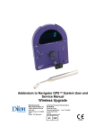
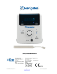
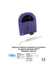
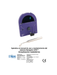
1
Addendum to Navigator GPS™ System User and Service Manual Wireless Upgrade Manufactured by: Dilon Technologies, Inc. 12050 Jefferson Avenue Suite 340 Newport News, VA 23606 USA Phone: 757-269-4910 Authorized European Representative: AG Medical Route de l'Orme, Parc des Algorithmes - Imm. "Homère" 91190 Saint-Aubin France http://ag-medical.com/ Addendum - GPS User Manual Important Note This document, and the information contained therein, is proprietary information of Dilon Technologies and may not be reproduced, copied in whole or in part, adapted, modified, disclosed to others, or disseminated without prior written consent of the Dilon Technologies. This document is intended to be used by customers as part of their Dilon Technologies equipment purchase. Dilon Technologies provides this document without warranty of any kind, implied or expressed, including, but not limited to, the implied warranties of merchantability and fitness for a particular purpose. Dilon Technologies has taken care to ensure the accuracy of this document. However, Dilon Technologies assumes no liability for errors or omissions, and reserves the right to make changes without further notice to any products herein, to improve reliability, function, or design. Dilon Technologies may make improvements or changes in the products or programs described in this document at any time. Navigator GPS is a trademark of Dilon Technologies. Other trademarks and trade names are those of their respective owners. Copyright Notice Copyright 2014 Dilon Technologies, Newport News, VA 23606 United States of America. Trademarks Dilon Technologies™ is a registered trademark of Dilon Technologies. All other company and product names are trademarks or registered trademarks of their respective owners. Part Number WP-5220-00-001 Rev 0 / July, 2014 WP-5220-00-001 Rev 0 2 Revised 7/22/2014 Addendum - GPS User Manual User Manual 1. Introduction...................................................................................................................................... 4 Description ......................................................................................................................................... 4 Intended Use ...................................................................................................................................... 4 Indications for Use ............................................................................................................................. 4 Manufacture and Distribution ............................................................................................................ 4 Trademarks ........................................................................................................................................ 4 Regulatory and Safety Requirements .............................................................................................. 5 2. Product Overview and Components ........................................................................................... 7 3. Precautions ...................................................................................................................................... 8 3A. General ........................................................................................................................................ 8 3B. Wireless Pilot Probe, Wireless Receiver and Navigator GPS Control Unit ........................... 8 4. Wireless Receiver ........................................................................................................................... 9 4A. Isotope Control ............................................................................................................................ 9 5. Cleaning, Disinfection, and Sterile Use of the wireless Pilot Probe ................................... 11 5A. Wireless Pilot Probe only ........................................................................................................ 11 5B. Radioactive Decontamination Procedure – OPTIONAL ........................................................ 12 5C. Cleaning/Storing Wireless Receiver ....................................................................................... 13 6. Probe Connectivity and Use ....................................................................................................... 14 Navigator GPS System with Wireless Upgrade ............................................................................ 14 7. Troubleshooting ............................................................................................................................ 19 8. Specifications ................................................................................................................................ 20 9. Support Items ................................................................................................................................ 21 9A. Product Part Numbers .............................................................................................................. 21 9B. Sterile Drape ............................................................................................................................. 21 10. Maintenance................................................................................................................................. 22 10A. Component Check .................................................................................................................. 22 10B. Verification of Standard Gain (Calibration Quick Test)........................................................ 22 11. Repair ............................................................................................................................................ 24 12. Limited Warranty ........................................................................................................................ 25 WP-5220-00-001 Rev 0 3 Revised 7/22/2014 Addendum - GPS User Manual USER MANUAL 1. Introduction Description This addendum to the Navigator GPS™ System User/Service Manual (PN GP-9200-96EN) details how to use the Wireless Upgrade option for existing Navigator Gamma Positioning Systems. This optional feature adds wireless gamma probe capability to Navigator GPS Control Units (PN-GP 2800-00). Use this addendum as a supplement to the Navigator GPS™ System User/Service Manual. If this manual is not readily available, download the electronic version from www.Dilon.com. The wireless receiver, when paired with the control unit, can only be used with the Wireless Pilot Probe™. The system is supplied non-sterile. This addendum includes guidelines for the use of the Wireless Pilot Probe and accessories within the sterile field. Intended Use For the detection and quantification of gamma radiation from gamma-emitting isotopes in the body or tissues. Use for non-imaging procedures to measure the amount of radionuclide absorbed by a particular organ or body region. Indications for Use For the detection and quantification of gamma radiation from gamma-emitting isotopes in the body or tissues. Use for non-imaging procedures to measure the amount of radionuclide absorbed by a particular organ or body region in open-surgical procedures. Manufacture and Distribution The system is manufactured and distributed by Dilon Technologies of Newport News, VA. Please direct all inquiries to Dilon Technologies. Trademarks The following are trademarks of Dilon Technologies: Navigator 2.0™, Wireless Pilot Probe™, Dilon Navigator GPS™, Dilon Navigator™, Dilon Technologies Navigator GPS™, Dilon Technologies Navigator™, Dilon Technologies Navigator 2.0™, Daniel Lung Probe™, and Navigator™ when used in context with the above. Navigator GPS® is a registered trademark of Dilon Technologies. WP-5220-00-001 Rev 0 4 Revised 7/22/2014 Addendum - GPS User Manual Regulatory and Safety Requirements The Dilon Navigator GPS™ System including Probes and accessories complies with the following standards: EC Directives EMC Directive 89/336/EEC Group l, Class B EN 55011 EMC Directive 89/336/EEC IEC 60601-1-2: 3rd Edition Reciprocal Interference The Wireless Upgrade components were designed, manufactured, and tested in accordance to the following standards recognized for Medical Devices under Directive 93/42/EEC: 1993. This product has been certified and tested by 3rd party testing facilities. • Medical Electrical Equipment - Part 1: General requirements For Safety 1: Collateral Standard: Safety Requirements For Medical Electrical Systems – IEC 60601-1-1: 3rd Ed. • Medical Electrical Equipment - Part 1: General Requirements For Safety Collateral Standard: Electromagnetic Compatibility - Requirements and Tests – IEC 60601-1-2: 3rd Ed. • Medical Electrical Equipment - Part 1: General requirements For Safety 1: Collateral Standard: Safety Requirements For Medical Electrical Systems – IEC 60601-1: 2nd & 3rd Ed. • Medical Electrical Equipment - Part 1: General Requirements For Safety Collateral Standard: Electromagnetic Compatibility - Requirements and Tests – IEC 60601-1-2: 3rd Ed. • Medical Electrical Equipment - Part 1-6: General Requirements For Safety Collateral Standard: Usability - IEC 60601-1-6: 3rd Ed. • Information supplied by the manufacturer of medical devices- EN 1041:2008 • Symbols for use in the labeling of medical devices - EN 980 :2008 • CAN/CSA C22.2 No. 60601-1, "Medical Electrical Equipment, Part 1: General Requirements for Safety & Essential Performance; issued 2008-02-01 Ed. 2 • AS/NZS 3200-1-0, Deviations to IEC 601-1 for Application in Australia and New Zealand CAUTION: Federal (USA) law restricts this device to sale and use by, or on the order of, a physician. WP-5220-00-001 Rev 0 5 Revised 7/22/2014 Addendum - GPS User Manual Table 1. Explanation of Symbols Attention, consult accompanying documents RX only Caution: Federal (USA) law restricts this device to sale and use by, or on the order of, a physician. Probe Isotope Control Acceptable shipping/storage conditions: -15° C to 40° C Serial number Lot #, or batch code FCC statements: “This device complies with part 15 of the FCC Rules. Operation is subject to the following two conditions: (1) This device may not cause harmful interference and (2) this device must accept any interference received, including interference that may cause undesired operation.” IC statements: “This device complies with Industry Canada license-exempt RSS standard(s). Operation is subject to the following two conditions: (1) This device may not cause interference and (2) this device must accept any interference, including interference that may cause undesired operation of the device.” Cet appareil est conforme avec Industrie Canada RSS exemptes de licence standard (s). Son fonctionnement est soumis aux deux conditions suivantes: (1) Ce dispositif ne doit pas causer d’interférences, et (2) cet appareil doit accepter toute interférence, y compris les interferences qui peuvent causer un mauvais fonctionnement de l’appareil. WP-5220-00-001 Rev 0 6 Revised 7/22/2014 Addendum - GPS User Manual 2. Product Overview and Components Table 2A-1. Probe Dimensions Probe Wireless Pilot Probe Tip Diameter Tip Angle Length 35° 260mm 14mm Weight 255g Table 2A-2. Receiver Dimensions Receiver Height Depth Weight Wireless Pilot Probe Receiver 25mm 68 mm 15g WP-5220-00-001 Rev 0 7 Revised 7/22/2014 Addendum - GPS User Manual 3. Precautions 3A. General The output of this system is not to be considered a diagnostic measure of the extent of disease in the patient, nor the recommended source of therapy. • Failure to thoroughly review and adhere to the information contained in this addendum and the Navigator GPS System User/Service Manual may pose a potential hazard to the patient and/or user and may void the warranty. 3B. Wireless Pilot Probe, Wireless Receiver and Navigator GPS Control Unit • • • • • • • • • Replace the wireless probe battery with a new battery on EACH day of use, before the first surgical procedure. This system is not designed for use in an explosive atmosphere. Keep the control unit off while connecting the wireless receiver. The probes, probe batteries, receiver and control unit are sold non-sterile. No components should be sterilized. DO NOT put any probe in an autoclave. With the exception of the Wireless Pilot Probe’s battery bay, DO NOT attempt to open probes. o All probes are tested and sealed at the factory. Attempting to open the probe may cause damage and will void the warranty. DO NOT drop the probe. DO NOT strike the probe tip against a hard surface; the detector element may become damaged and no longer be able to measure radiation. o This will also void the warranty. WP-5220-00-001 Rev 0 8 Revised 7/22/2014 Addendum - GPS User Manual 4. Wireless Receiver 4A. Isotope Control The wireless receiver allows the user to adjust the system’s isotope setting, specific to the isotope in use. When the wireless receiver is connected to the control unit, and the control unit is turned on, the isotope control will automatically default to the Tc99 setting. CAUTION: It is important that the isotope control is set to the isotope to be used in the procedure. Setting the isotope control incorrectly will result in incorrect detection. WP-5220-00-001 Rev 0 9 Revised 7/22/2014 Addendum - GPS User Manual Table 4A-1. Isotopes Switch set on: I125 Switch set on: 511keV Switch set on: In111 Switch set on: Tc99 Iodine-125 18 Technetium-99m F-FDG (and I131) Indium111 The Wireless Receiver and Navigator GPS Control Unit must both be set to the same isotope setting. For Navigator GPS units built after 2006, the isotope control setting on the back of the device will illuminate the corresponding light on the control unit’s isotope indicator. For earlier Navigator GPS systems that lack the isotope indicator (built between 1999 and 2006), check the back of the control unit to ensure that the isotope setting switch matches the isotope specified on the receiver. Table 4A-2. Controls and Displays on the Front of the Wireless Receiver Control Display Description Power LED: Indicates that the signal between receiver and Pilot Probe is connected. It will flash during receiving transmission from the probe Isotope Indicators: Select the isotope to be detected by the control unit. Be sure to select the same isotope on the back of the Control Unit as well. See “Isotope Control” section of Navigator GPS System User/ Service Manual for more information. WP-5220-00-001 Rev 0 10 Revised 7/22/2014 Addendum - GPS User Manual 5. Cleaning, Disinfection, and Sterile Use of the wireless Pilot Probe All probes require cleaning and disinfecting immediately after use. Follow these steps to ensure that cleaning and disinfection are done correctly. • • • • Before Use, visually inspect probe to ensure that it is free of contamination During Use, place probe in a sterile drape After Use, Clean/Disinfect/Store Probe OPTIONAL: Radioactive Decontamination Procedure –(see section 5B) 5A. Wireless Pilot Probe only The Wireless Pilot Probe and all other Dilon probes and accessories are sold non-sterile. WARNING! Before cleaning, inspect probe to ensure its integrity. Compromised probes can be further damaged as a result of the cleaning process. Probes in poor condition due to wear and fatigue should be returned to Dilon Technologies for repair. Table 5A-1. Cleaning Preparation for cleaning: Remove battery from Wireless Pilot Probe, and secure battery cap to the bottom of probe before cleaning. Cleaning Equipment: Enzymatic detergent, OPA high-level disinfectant, running water Cleaning Method: Drying: 1. Rinse the outside surfaces of the probe with a brisk stream of lukewarm tap water (98°F to 105°F / 36.5°C to 40.5°C). Prepare enzymatic cleaner, suitable for surgical instruments, according to the manufacturer's recommendation. 2. Swirl the proximal end of the probe in enzymatic cleaner for a minimum of 10 seconds. Thoroughly scrub the plastic end-cap with a toothbrush-style, latex-free nylon bristle cleaning brush (i.e. Key Surgical N-3000, or a similar brush). 3. Lightly scrub the probe and lens with a latex-free nylon bristle cleaning brush. Repeat separately for collimator cleaning, if used. 4. Wipe the entire probe with soft cloth or sponge soaked in enzymatic cleaner. 5. Visually inspect device(s) for contaminated areas. 6. Repeat steps 2 through 5 until visual inspection reveals instrument(s) is clean. 7. Rinse equipment with a brisk stream of lukewarm tap water (98°F to 105°F / 36.5°C to 40.5°C) for 30-seconds. 8. Prepare OPA high-level disinfectant solution according to manufacturer’s instructions. 9. Immerse probe completely for a minimum of 12 minutes at 68°F (20°C) or higher, to destroy all pathogenic microorganisms. Note that probes that are compromised can be damaged if detergent seeps into them. 10. Rinse with a brisk stream of tap water (98°F to 105°F / 36.5°C to 40.5°C) for approximately 1 minute. Repeat rinse two additional times. Air-dry or dry with clean towel. WP-5220-00-001 Rev 0 11 Revised 7/22/2014 Addendum - GPS User Manual CAUTION: Do not contaminate other items by wiping them with used cleaning solution. CAUTION: The cleaning instructions provided above have been validated by the medical device manufacturer, for preparing this device for re-use. It remains the responsibility of the re-processor to ensure that the reprocessing is actually performed using qualified equipment, materials, and personnel in the processing facility, to achieve the desired result. This requires validation and routine monitoring of the process. Likewise, any deviation by the processor from the instructions provided should be properly evaluated for effectiveness and potential adverse consequences. 5B. Radioactive Decontamination Procedure – OPTIONAL An increase in background counts may signal radioactive contamination of the probe or the environment. If a process of elimination shows the probe to be contaminated with radioactive material, the probe must be decontaminated. 1. Decontaminate the probe using standard Nuclear Medicine Department techniques, which may involve washing the probe with a solution such as Radiacwash™. 2. Ensure that all recesses, crevices, and mating surfaces are clean. 3. Dispose of pads and cleaning solution in approved containers. WP-5220-00-001 Rev 0 12 Revised 7/22/2014 Addendum - GPS User Manual 5C. Cleaning/Storing Wireless Receiver 1. If unclean, wipe wireless receiver with a soft cloth moistened with mild soap and water. Dry with a soft cloth. 2. Store the receiver in a clean, safe environment. CAUTION: Follow universal, generally accepted practices when handling components that have come in contact with blood or tissue. WP-5220-00-001 Rev 0 13 Revised 7/22/2014 Addendum - GPS User Manual 6. Probe Connectivity and Use Navigator GPS System with Wireless Upgrade The Navigator GPS is compatible with the wireless Pilot Probe. A typical sequence of setting up the Wireless Pilot Probe for a procedure with Technetium-99m isotope (such that would be used in a lymphatic mapping procedure for a sentinel node biopsy) is as follows: WP-5220-00-001 Rev 0 14 Revised 7/22/2014 Addendum - GPS User Manual 6-1. Before Surgery • • • • • • • Insert a fully charged PowerPak (battery) into the Navigator GPS control unit (see Navigator GPS System User/Service Manual for insertion instructions). Attach the wireless receiver to the cable port on the front of the control unit. Note that the isotope indicator will default to Tc 99 when turned on. An LED will illuminate on the receiver once the control unit is on. Upon initial insertion of new Wireless Pilot Probe battery, probe may need to be lightly shaken to activate LED in probe base. A flashing LED on the Pilot Probe indicates that it is linked with control unit and ready for use. When placed in a resting position, the LED turns off within seconds, to save energy. When the Pilot Probe is moved, it instantly powers up for immediate use. For intraoperative use, insert the Wireless Pilot Probe into a sterile drape. Insert a probe battery into the Pilot Probe as follows. 1. Hold probe firm; turn battery cap counterclockwise and remove from probe. Inspect O-ring integrity. If O-ring is missing or damaged, use new battery cap. Contact Dilon Technologies or your distributor for battery cap reorder information. • WP-5220-00-001 Rev 0 15 Revised 7/22/2014 Addendum - GPS User Manual 2. Install one 3V CR 2 lithium battery in Pilot Probe battery holder with positive (+) end facing toward the base of the probe and negative (-) end toward the middle of the probe. Incorrect placement of battery into battery holder for extended periods of time will cause battery to drain quickly. . 3. Insert battery holder into probe negative (-) end in. Lightly turn until holder lowers into place. 4. Hold probe firm; push battery cap into probe and turn clockwise until O-ring is no longer visible. • Upon initial insertion of new Wireless Pilot Probe battery, probe may need to be lightly shaken to activate LED in probe base. • LED on the Pilot Probe indicates that it is linked with control unit and ready for use. When placed in a resting position, the LED turns off within seconds, to save energy. When the Pilot Probe is moved, it instantly powers up for immediate use. • For intraoperative use, insert the Pilot Probe into a sterile drape. WP-5220-00-001 Rev 0 16 Revised 7/22/2014 Addendum - GPS User Manual Table 6-1. Wireless Receiver - LED Power Indicator Indication Status On/Flashing Wireless receiver and Wireless Pilot Probe are linked and ready for use. The GPS system is off, or there may be a connection error between the receiver and the control unit. Off Table 6-2. Wireless Pilot Probe LED Indicator Indication Status On/Flashing Probe is linked and ready for use Probe is in a resting position to conserve power; to reactivate LED indicator, simply pick up probe, or if needed, lightly shake probe. Off If no power upon ready to use, the battery needs to be installed or replaced. If battery has been replaced and LED light is still off, contact your distributor or Dilon Technologies directly. 6-2. During Surgery • NOTE: For Technetium-99m (Tc 99), the control unit settings are given in the following table. • Table 6-3. Navigator GPS with Wireless Pilot Probe - Settings and Indicators w/ Tc 99 Example Control/Indicator Setting Controls (back of Control Unit) SCAN/Calibrate SCAN Isotope Tc 99 Indicators (front of the Control Unit) Range 1x Threshold Illuminated; this control is for CABLED PROBES only. The Wireless Pilot Probe features integrated threshold, which controls the count range of photon energy detected by the probe. Display 0 Isotope Tc 99 Probe LED Indicator (bottom of the Pilot Probe handle) Probe LED Illuminated/Flashing Wireless Receiver Receiver LED Illuminated/Flashing Isotope Tc 99 6-3. After Surgery WP-5220-00-001 Rev 0 17 Revised 7/22/2014 Addendum - GPS User Manual • See: ‘Cleaning, Disinfection, and Sterile Use of Probe’ (Section 5). WP-5220-00-001 Rev 0 18 Revised 7/22/2014 Addendum - GPS User Manual SERVICE MANUAL 7. Troubleshooting With the exception of the Wireless Pilot Probe’s battery holder, there are no serviceable components within the Wireless Pilot Probe body, or wireless receiver. Contact your representative or Dilon Technologies for additional assistance if more detail is required. Table 7-1. Navigator GPS Control Unit with WIRELESS PILOT PROBE- Settings and Indicators Problem Possible Causes Remedies 1. Zero in display. No signal under presence of a radioactive source. No connection between probe, receiver and control unit. Check that the connection between the receiver and control unit is secure. No connection between probe, receiver and control unit. Replace the probe battery Isotope control indicates incorrect isotope. Change isotope control (on front of wireless receiver) to desired isotope. Circuit inside the control unit has been damaged. Try a different control unit. Contact Dilon Technologies for assistance. Probe is damaged. Try a different probe, or contact Dilon Technologies for assistance. Wireless receiver is damaged. Try a different receiver, or contact Dilon Technologies for assistance. No connection between wireless receiver and control unit. Check that the wireless receiver is securely connected to the control unit. LED on wireless receiver is damaged. Contact Dilon Technologies for assistance. No connection between wireless receiver and control unit. Check that the connection between the wireless receiver and control unit is secure. LED on wireless receiver is damaged. Contact Dilon Technologies for assistance. LED on probe is damaged. Contact Dilon Technologies for assistance. Probe LED is illuminated but not transmitting signal to unit (LED flashes when transmitting) Gently shake probe to activate connectivity. Probe battery is dead. Replace with new battery. Battery was not installed. Install new battery. 2. LED on wireless receiver does not illuminate when power is on. 3. Isotope control on wireless receiver does not illuminate when power is on. 4. LED on Pilot Probe does not light as indicated WP-5220-00-001 Rev 0 19 Revised 7/22/2014 Addendum - GPS User Manual 8. Specifications The Wireless Upgrade consists of the wireless receiver, Wireless Pilot Probe, and probe batteries. Table 8A-1. Wireless Upgrade Specifications Item Description Wireless Pilot Probe Power Source Replaceable, Internal battery Battery Single use CR2; 3 V Lithium; capacity 1550 mAh Wireless Distance Pilot Industry Standard Frequency Probe Transmission Up to 9 meters Wireless Operating 2.4 GHz Visual Indicators Wireless Receiver: • • Power On – LED Isotope – LED (four) Wireless Pilot Probe: • • Storage Conditions Probe Connection – LED Isotope – LED (four) Operating Temperature Range: 15°C to 40°C (5°F to 104°F) Humidity: 0%-80% relative humidity Atmospheric Pressure: 50 kPa to 106 kPa WP-5220-00-001 Rev 0 20 Revised 7/22/2014 Addendum - GPS User Manual 9. Support Items The Wireless Upgrade is typically supplied as a complete system (Part # WP-9220-00). Support items may be purchased from the local Dilon Technologies Navigator representative. At time of publication of this addendum, the primary support items have the following part numbers. Feel free to contact your local representative for additional information. 9A. Product Part Numbers Table 9A-1. Product Part Numbers Item Dilon Part Number Wireless Receiver for Navigator GPS WP-8000-01 Wireless Pilot Probe WP-9000-14 Wireless Pilot Probe Batteries (Pack of 10) WP-8500-01 Wireless Pilot Probe Battery End Cap WP-2000-10 Wireless Pilot Probe Battery Holder WP-9050-00 Optional Top Gun Collimator SP-1800-00 9B. Sterile Drape A sterile drape is an accessory that is not sold or supported by Dilon Technologies. Typical characteristics of a suitable intra-operative probe drape are as follows: • • • • • Universal Gamma Probe Cover 5 x 24 Sized with tapered tip to fit both straight and flexible probes Low density, soft polyethylene Telescopically folded w/rubber bands and medical grade tape strips Drape features: o All components, including rubber bands, guaranteed 100% Latex-free o All available EtO Sterile o Strong and durable Anti-Static material WP-5220-00-001 Rev 0 21 Revised 7/22/2014 Addendum - GPS User Manual 10. Maintenance 10A. Component Check While Wireless Upgrade is virtually maintenance-free, a check of each system component for any visible signs of abuse, neglect, or wear, should be conducted before each use and storage. This includes checking the following: Table 10A-1. Component Check Component Feature Wireless Pilot Probe Overall check - Also probe bay, battery cap and O-ring Wireless Receiver Overall check - Housing, integrity of its electrical connector and the connector pins Do not use a damaged probe, wireless receiver, or probe batteries. Should abnormalities be discovered, contact Dilon Technologies directly. 10B. Verification of Standard Gain (Calibration Quick Test) All Dilon Technologies Navigator systems are designed to minimize periodic maintenance, such that may be performed by a clinical engineering department or the manufacturer. Some institutions, however, do choose to perform ‘Verification of Standard Gain’ tests every six months or every year. The procedure does not calibrate the system; it simply reveals whether or not the probe and control unit are set to a common gain standard (calibration). That common standard relates the gamma photon energy detected by the probe, to an energy window inside the control unit. The Verification of Standard Gain uses 122 keV energy photons produced by the Isotope of Cobalt-57 to create a known signal in the probe. The control unit expects these detected photons to be in an energy window corresponding to the CENTERED position of the test. The control unit also has a test setting for an energy window BELOW the expected signal, and an energy window for a signal ABOVE the expected signal. The desired outcome of the test is that the signal is greatest in the CENTERED position, as revealed by the highest count rate seen in the control units' display. The details of the test are given below. 10B-1. Verification of Standard Gain (Calibration Quick Test) – Procedure 1. Clean the PROBE. 2. Charge the POWERPAK, and install it into the CONTROL UNIT. 3. Place the system controls as indicated in Table 10B-1, “System Configuration - Cobalt-57 Alignment.” 4. Align a Cobalt-57 source directly with the probe tip. Maintain this exact position between the source and the probe tip for the duration of the test. 5. Place the system controls as indicated in Table 10B-1 “System Configuration - Cobalt-57 Alignment.” 6. Place the SCAN/Calibrate Control in the CENTERED position, which is indicated by the following symbol on the SCAN/Calibrate Control (>0<). Obtain a ten-second count. Record this total. 7. Place the SCAN/Calibrate Control in the BELOW position which is indicated by the WP-5220-00-001 Rev 0 22 Revised 7/22/2014 Addendum - GPS User Manual following symbol on the SCAN/Calibrate Control (-). Press the COUNT control to obtain a ten-second count. Record this total. 8. Place the SCAN/Calibrate Control in the ABOVE position which is indicated by the following symbol on the SCAN/Calibrate Control (+). Obtain a ten-second count. Record this total. 9. The highest count should be when the SCAN/Calibrate Control is in the CENTERED (>0<) position. The count in the ABOVE position (+) and the count in the BELOW position (-) should be less than the count in the CENTERED (>0<) position. The observance of these relationships verifies that the probe and control unit have the same standard gain. 10. Return the SCAN/Calibrate Control to the SCAN position. 11. Return the other system controls to the settings for normal use. 12. End of Test. NOTE: Because the system is designed to detect slight changes in the location and intensity of radioisotopes, the test source must be maintained in the same direct alignment and distance from the probe tip throughout the calibration tests. NOTE: The front panel CALIBRATION INDICATOR blinks when the SCAN/Calibrate Control is in either the BELOW (-), CENTERED (>0<), or ABOVE (+) test position. The CALIBRATION INDICATOR is OFF when the CALIBRATION control is in the SCAN position. Table 10B-1. System Configuration – Cobalt-57 Alignment, Calibration Quick Test Component/Feature Item Wireless Pilot Probe New battery in probe - Probe LED ON/Flashing Wireless Receiver Receiver connected to control unit - LED ON/Flashing Control Unit POWER switch ON CALIBRATE control (rear panel)(>0<), (-), (+) ISOTOPE control (rear panel) Tc 99 THRESHOLD control As desired (no effect) RANGE control As desired VOLUME control As desired WP-5220-00-001 Rev 0 23 Revised 7/22/2014 Addendum - GPS User Manual 11. Repair The Wireless Pilot Probe is sealed at the factory. No user serviceable parts are inside the probes. Damage to a probe may result if a probe is opened by the user and will void any remaining warranty, if attempted. Please contact Dilon Technologies for additional service. An RMA number is required upon return for service. • 12050 Jefferson Avenue Suite 340 Newport News, VA 23606 USA Phone: +1-844-DILONNAV www.Dilon.com CAUTION: Before using loose packing materials, such as foam pellets, shredded paper, or excelsior, be sure to wrap the component(s) separately in plastic bags or film or other protective wrapping.. • CAUTION: If a system, or system components are to be shipped from your institution for repair, then please clean and disinfect the components as described in this manual before packing for shipment. Dilon Technologies requires that a Navigator Service Sheet be attached to the outside of the shipping box, certifying that the items have been cleaned and disinfected to manufacturer’s specifications. This form can be found on the Dilon Technologies website (www.Dilon.com) or by contacting your distributor or Dilon Technologies directly. WP-5220-00-001 Rev 0 24 Revised 7/22/2014 Addendum - GPS User Manual 12. Limited Warranty Dilon Technologies (Dilon), warrants to its customers that, subject to the below provisions, the Wireless Upgrade will be free from defects in materials and workmanship for twelve (12) months, commencing upon the date of shipment from Dilon. Replacement parts and products are warranted to be free from defects in material and workmanship for a period equal to the balance of the warranty period remaining on the original part or product. Dilon will repair or replace, at its option and without charge, any of the above products which are returned to Dilon or its designated repair site, within the applicable warranty period, with prepayment of shipping costs, and which are determined by Dilon to be defective in materials or workmanship. This Limited Warranty does not apply to any product or replacement part or replacement product which has been subjected to any damage as a result of an accident or abuse, or that has not been used and maintained in accordance with the information contained in the literature accompanying the product, or that has been modified, repaired or serviced by any person or company other than Dilon or its authorized representative. Dilon’s sole liability for any defective product shall be repaired or replaced as set forth above. Dilon shall not be liable to anyone, under any circumstances, for any special, punitive, incidental or consequential damages whatsoever, including without limitation any costs, expenses, lost profits or other losses however designated. EXCEPT AS STATED ABOVE, NO WARRANTIES ARE EXPRESSED OR IMPLIED, INCLUDING WITHOUT LIMITATION ANY WARRANTIES OF MERCHANTABILITY OR FITNESS FOR A PARTICULAR PURPOSE, AND, EXCEPT AS STATED ABOVE, DILON EXPRESSLY DISCLAIMS ALL WARRANTIES. Manufactured by: Authorized European Representative: Dilon Technologies 12050 Jefferson Avenue Suite 340 Newport News, VA 23606 USA Phone: +1-844-DILONNAV www.Dilon.com AG Medical Route de l'Orme, Parc des Algorithmes - Imm. "Homère" 91190 Saint-Aubin , France http://ag-medical.com/ 2014 Dilon All Rights Reserved. May 2014 Made in USA WP-5220-00-001 Rev 0 25 Revised 7/22/2014 Addendum - GPS User Manual WP-5220-00-001 Rev 0 26 Revised 7/22/2014