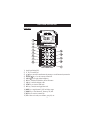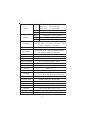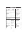
1
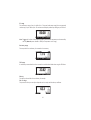
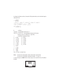
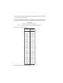
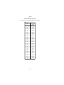
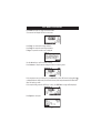
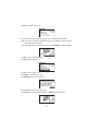
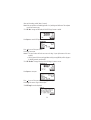
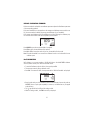
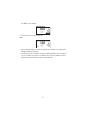
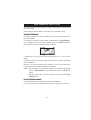
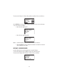
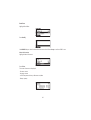
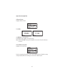
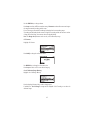
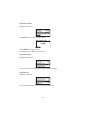
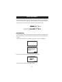
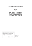
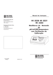
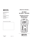
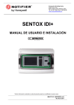
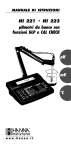
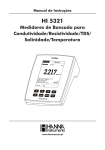
Instruction Manual
HI 98192
USP Compliant
EC, TDS, NaCl, Resistivity,
Temperature Meter
w w w. h a n n a i n s t . c o m
1
Dear Customer,
Thank you for choosing a Hanna Instruments product.
Please read this instruction manual carefully before using the instrument.
This manual will provide you with the necessary information for correct use of the instrument, as well
as a precise idea of its versatility.
If you need additional technical information, do not hesitate to e-mail us at [email protected] or
view our worldwide contact list at www.hannainst.com.
WARRANTY
The HI 98192 is guaranteed for two years against defects in workmanship and materials when used
for their intended purpose and maintained according to instructions. Electrodes and probes are
guaranteed for six months. This warranty is limited to repair or replacement free of charge.
Damage due to accidents, misuse, tampering or lack of prescribed maintenance is not covered.
If service is required, contact the dealer from whom you purchased the instrument. If under warranty,
report the model number, date of purchase, serial number and the nature of the problem. If the repair
is not covered by the warranty, you will be notified of the charges incurred. If the instrument is to be
returned to Hanna Instruments, first obtain a Returned Goods Authorization number from the Technical
Service department and then send it with shipping costs prepaid. When shipping any instrument,
make sure it is properly packed for complete protection.
All rights are reserved. Reproduction in whole or in part is prohibited without the written consent of the
copyright owner, Hanna Instruments Inc., Woonsocket, Rhode Island, 02895, USA.
2
TABLE OF CONTENTS
WARRANTY .......................................................................................................................... 2
PRELIMINARY EXAMINATION ................................................................................................. 3
GENERAL DESCRIPTION ......................................................................................................... 4
FUNCTIONAL DESCRIPTION ................................................................................................... 5
SPECIFICATIONS .................................................................................................................. 7
OPERATIONAL GUIDE ............................................................................................................ 9
AUTORANGING ................................................................................................................... 14
TEMPERATURE COMPENSATION ........................................................................................... 15
CONDUCTIVITY VERSUS TEMPERATURE CHART ...................................................................... 16
USP MEASUREMENT .......................................................................................................... 17
USP MODE PROCEDURES .................................................................................................... 21
USER CALIBRATION ............................................................................................................ 25
EC CALIBRATION ................................................................................................................ 26
GOOD LABORATORY PRACTICE (GLP) ..................................................................................... 33
SETUP ............................................................................................................................... 35
LOG ON DEMAND ............................................................................................................... 47
AUTOLOG ........................................................................................................................... 50
AutoEnd ............................................................................................................................ 52
TEMPERATURE CALIBRATION (for technical personnel only) .................................................... 53
PC INTERFACE .................................................................................................................... 56
BATTERIES REPLACEMENT ................................................................................................... 63
TROUBLESHOOTING GUIDE ................................................................................................. 64
PROBE MAINTENANCE ........................................................................................................ 65
ACCESSORIES .................................................................................................................... 66
PRELIMINARY EXAMINATION
Remove the instrument from the packing material and examine it carefully to make sure that no
damage has occurred during shipping. If there is any damage, notify your dealer or the nearest Hanna
Customer Service Center.
Each instrument is supplied with:
• HI 763133 4-ring probe with temperature sensor (4 m cable)
• HI 7031M 1413 µS/cm calibration standard (230 ml)
• HI 7035M 111.8 mS/cm calibration standard (230 ml)
• HI 92000 PC software
• HI 920015 Micro USB cable
• 100 mL Plastic Beaker (2 pcs.)
• 4 x 1.5 V AA Batteries
• Instruction Manual
3
• Rugged carrying case
Note: Save all packing material until you are sure that the instrument functions correctly. All defective
items must be returned in the original packing with the supplied accessories.
GENERAL DESCRIPTION
The HI 98192 instrument is state-of-the-art, heavy-duty conductivity meter, designed to provide
laboratory results and accuracy under harsh industrial conditions.
The USP standard compliance makes the instrument useful for pure water determination.
It is provided with a series of new diagnostic features which add an entirely new dimension to the
measurement of conductivity, by allowing the user to dramatically improve the reliability of the
measurement:
• 7 memorized standards (0.00 µS/cm, 84.0 µS/cm, 1.413 mS/cm, 5.00 mS/cm, 12.88 mS/
cm, 80.0 mS/cm and 111.8 mS/cm) for calibration.
• EC calibration up to five calibration points.
• Messages on the graphic LCD for an easy and accurate calibration.
• Diagnostic features to alert the user when the electrode needs cleaning.
• User-selectable “Outside Calibration Range” warning.
• User-selectable “calibration time out” to remind when a new calibration is necessary.
Moreover, they offer an extended temperature range from -20 to 120 °C (-4 to 248 °F), using
temperature sensor inside EC electrode.
This instrument can also measure in Resistivity, TDS and Salinity ranges. Three salinity modes are
available: % NaCl, Practical salinity and Natural seawater scale.
Other features include:
• Temperature source selection
• Temperature automatic compensation, linear or non linear user selectable
• Temperature reference selection 15 °C, 20 °C or 25 °C.
• Temperature coefficient set
• Log on demand up to 400 samples
• Auto Log feature up to 1000 records
• Auto Hold feature, to freeze first stable reading on the LCD
• Lock and user setup Fixed range selection
• GLP feature, to view last calibration data for EC, NaCl
• Probe change recognition
• PC interface
• Probe replatinization
4
FUNCTIONAL DESCRIPTION
FRONT VIEW
1) Liquid Crystal Display (LCD).
2) F1, F2, F3 functional keys.
3) / keys to manually increase/decrease the parameters or to scroll between the parameter list.
4) ON/OFF ( ) key, to turn the instrument ON and OFF.
5) LIGHT ( ) key to toggle display backlighting.
6) GLP key, to display Good Laboratory Practice information.
7) CAL key, to enter/exit calibration mode.
8) SETUP key, to enter/exit SETUP mode.
9) RCL key, to enter/exit view logged data mode.
10) MODE key to toggle between EC, USP and Salinity ranges.
11) RANGE key, to switch between EC, Resistivity, TDS, NaCl.
12) HELP key to enter/exit contextual help.
13) ESC to leave current mode, exit calibration, setup, help. etc.
5
TOP VIEW
14) Electrode DIN connector.
15) USB connector.
6
SPECIFICATIONS
Range
EC
Resolution
Accuracy
Range
Resistivity
Resolution
Accuracy
TD S
Range
Resolution
Accuracy
0 to 400 mS/cm
(shows values up to 1000 mS/cm)
Actual conductivity 1000 mS/cm
0.001 to 9.999 µS/cm*
10.00 to 99.99 µS/cm
100.0 to 999.9 µS/cm
1.000 to 9.999 mS/cm
10.00 to 99.99 mS/cm
100.0 to 1000.0 mS/cm
(autoranging)
0.001 µS/cm* / 0.01 µS/cm / 0.1 µS/cm
0.001 mS/cm / 0.01 mS/cm / 0.1 mS/cm
±1% of reading (±0.01 µS/cm or 1 digit whichever
greater)
1.0 to 99.9 ohms
100 to 999 ohms
1.00 to 9.99 Kohms
10.0 to 99.9 Kohms
100 to 999 Kohms
1.00 to 9.99 Mohms
10.0 to 100.0 Mohms*
(autoranging)
0.1 ohms / 1 ohms / 0.01 Kohms / 0.1 Kohms / 1 Kohms
0.01 Mohms / 0.1 Mohms*
±1% of reading (±10 ohms or 1 digit whichever greater)
0.00 to 99.99 ppm
100.0 to 999.9 ppm
1.000 to 9.999 g/L
10.00 to 99.99 g/L
100.0 to 400.0 g/L
(autoranging)
0.01 ppm / 0.1 ppm / 0.001 g/L / 0.01 g/L / 0.1 g/L
±1% of reading (±0.05 ppm or 1 digit whichever greater)
* The 0.001 µS/cm EC range and 0.1 MOhms Resistivity range are not available with the 4 m
cable probe.
7
Range
% NaCl:
Seawater scale:
Practical salinity:
0.0 to 400.0 %
0.00 to 80.00 (ppt)
0.01 to 42.00 (PSU)
Salinity
Resolution
0.1 % / 0.01
Accuracy
±1% of reading
Range
-20.0 to 120.0 °C (-4.0 to 248.0 °F)
Temperature
Resolution
0.1 °C (0.1 °F)
Accuracy
±0.2 °C (±0.4 °F) (excluding probe error)
Automatic up to five points with seven memorized standards (0.00
EC Calibration
µS/cm, 8 4. 0 µ S/ cm, 1. 4 1 3 m S/ cm, 5. 0 0 m S/ cm, 1 2. 8 8
m S/ cm, 80.0 mS/cm, 111.8 mS/cm)
Cell Constant Setup
0.010 to 10.000
Max. one point only in % range (with HI 7073 standard);
NaCl Calibration
use conductivity calibration for other ranges
Implemented Standards
USP compliant
HI 763133 (8 pin DIN, 4m cable)
EC Probe
Temperature Source
Automatic from sensor inside the probe; Manual entry
Temperature Compensation
NoTC, Linear, Non Linear ISO/DIS 7888 std
Reference Temperature
15, 20, 25 °C
Temperature Coeficient
0.00 to 10.00 %/°C
TDS Factor
0.40 to 1.00
Log on Demand
400 samples
5, 10, 30 sec,
Lot Logging
1, 2, 5, 10, 15, 30, 60, 120, 180 min (max 1000 samples)
Memorized Profiles
Up to 10
Measurement Modes
Autorange, AutoEnd, LOCK and fixed range
Battery Type / Life
4 x 1.5V AA batteries / 100h no backlight 25h with backlight
Auto Power Off
User selectable: 5, 10, 30, 60 minutes or disabled
PC Interface
Opto-isolated USB
Dimensions
185 x 93 x 35.2 mm (7.3 x 3.6 x 1.4”)
Weight
400 g
Environment
0 to 50 °C (32 to 122 °F) max. RH 100% IP 67
8
OPERATIONAL GUIDE
INITIAL PREPARATION
The instrument is supplied complete with batteries. See Batteries Replacement for details, page 63.
To prepare the instrument for field measurements close the serial communication socket with proper
stopper (to ensure waterproof protection).
Connect the EC probe to the DIN connector on the top of the instrument. Tighten the thread ring. Make
sure the probe sleeve is properly inserted.
Turn the instrument ON by pressing ON/OFF key.
At start-up the display will show the Hanna logo for a few seconds followed by the percentage indication
of the remaining battery life and the “Loading Log...” message, then enters the measurement mode.
The Auto Power Off feature turns the instrument off after a set period (default 30 min) with no button
pressed to save battery life. To set another period or to disable this feature, see SETUP menu on page 35.
The instrument continues to monitor the inputs and memorize readings if the automatic logging is
enabled and started. To stop autologging press StopLog key or simply power off the instrument by
pressing the ON/OFF key.
The Auto Light Off backlight feature turns the backlight off after a set period (default 1 min) with no
buttons pressed. To set another period or to disable this feature, see SETUP menu on page 35.
MEASUREMENTS
Immerse the probe into the solution to be tested. The sleeve holes must be completely submerged. Tap
the probe repeatedly to remove any air bubbles that may be trapped inside the sleeve.
If needed, press RANGE repeatedly until the desired range (EC, Resistivity, TDS, Salinity) is selected
on the LCD.
Allow for the reading to stabilize. The main LCD line displays the measurement in the selected range,
while the temperature is displayed on the lower LCD line.
9
EC range
The conductivity range is from 0 to 400 mS/cm . The actual conductivity range (the uncompensated
conductivity) is up to 1000 mS/cm. The instrument will display conductivity readings up to 1000 mS.
Note: The symbol in front of the temperature reading means that the temperature can be entered by
the user (Manual option selected in SETUP, or temperature out of range).
Resistivity range
The reciprocal of the conductivity of a material is the resistivity.
TDS range
A conductivity measured value can be corrected to a total dissolved solids value using the TDS factor.
Salinity
The salinity is derived from the conductivity of a sample.
Salt % range
The percent of salinity in a sample is dependent on the sample and the salinity coefficient.
10
For practical reasons, the salinity of a solution is derived from the salinity of the seawater. Two
methods of calculating the salinity from the conductivity are supported:
• Natural seawater scale
• Practical salinity scale
Natural seawater scale (UNESCO 1966)
According to the definition, salinity of a sample in ppt is calculated using the following formula:
C (sample)
RT= T
C(35;15)·rT
rT=1.0031·10-9 T4–6.9698·10-7 T3+1.104259·10-4 T2+2.00564·10-2 T+6.766097·10-1
R=RT+10-5RT(RT–1.0)(T–15.0)[96.7-72.0RT+37.3RT2–(0.63+0.21RT2)(T–15.0)]
S=-0.08996+28.2929729R+12.80832R2–10.67869R3+5.98624R4–1.32311R5
where:
RT
- coefficient;
CT(sample) - uncompensated conductivity at T °C;
C(35;15)= 42.914 mS/cm - the corresponding conductivity of KCl solution
containing a mass of 32.4356 g KCl / 1 Kg solution;
rT
- temperature compensation polynom.
Note: The formula can be applied for temperatures between 10 °C and 31 °C.
To access this range press Mode while in Salinity range until the seawater scale [SW] is displayed.
Practical salinity scale
This is a practical scale based on the precise measurement of the electrical conductivity of a solution
with a known salinity range.
The relationship derived from the scale relates salinity, conductivity, temperature and pressure and
use a solution with a salinity of 35 ‰ as datum point. This is taken to have a conductivity of 42.914
mS/cm of 15 °C at standard atmospheric pressure.
11
According to the definition, salinity of a sample in PSU (practical salinity units) is calculated using the
following formula:
RT
- coefficient;
CT(sample) - uncompensated conductivity at T °C;
C(35,15)= 42.914 mS/cm - the corresponding conductivity of KCl solution
containing a mass of 32.4356 g KCl / 1 Kg solution;
rT
- temperature compensation polynom
a0 = 0.008
b0=0.0005
a1 = -0.1692
b1= -0.0056
a2 = 25.3851
b2= -0.0066
a3 = 14.0941
b3= -0.0375
a4 = -7.0261
b4= 0.0636
a5 = 2.7081
b5= -0.0144
c0 = 0.008
c1 = 0.0005
X = 400RT
Y = 100RT
f (T)= (T-15)/[1+0.0162(T-15)]
Notes: • The formula can be applied for salinity values between 0 and 42 PSU.
• The formula can be applied for temperatures between -2 °C and 35 °C.
To reach this range press Mode while in Salinity range until the practical salinity scale [PSU] is
displayed.
12
Notes:
• If the meter displays the top of the range blinking, the reading is out of range.
• If the stability indicator “ ” blinks, the reading is unstable.
• Make sure the meter is calibrated before taking measurements.
• If measurements are taken successively in different samples, for accurate readings it is recommended
to rinse the probe thoroughly with deionized water before immersing it into the samples.
• TDS reading is obtained by multiplying the EC reading by the TDS factor, which has a default value
of 0.50. It is possible to change the TDS factor in the 0.40 to 1.00 range by entering SETUP mode.
The probes designed to work with this instrument have an internal ID identification. Every time the
instrument detects probe changing, it reminds the user to update the cell constant of the new probe
being used and to calibrate in the appropriate EC range.
13
AUTORANGING
The EC, Resistivity and TDS scales are autoranging. The meter automatically sets the scale with the
highest possible resolution.
By pressing Lock, the autoranging feature is disabled and the current range is frozen on the LCD.
The “Range: Locked” message is displayed. To restore the autoranging option press “AutoRng”
functional key again.
The autoranging mode is also disabled by selecting a “fixed range” in the SETUP menu. While in
fixed range mode the instrument will display the readings with the fixed resolution. A maximum of 6
digits can be displayed. The top of the fixed range is displayed blinking when the reading exceeds
this value.
To disable fixed range mode enter SETUP and select autoranging mode.
Note: Autoranging is automatically restored if the range is changed, if the calibration mode is
entered, or if the meter is turned off and back on again.
14
TEMPERATURE COMPENSATION
Two selectable temparature sources are available: reading directly from the sensor inside the probe or
manual entry.
Three options of compensating temperature are available:
Linear Temperature Compensation: The conductivity of a solution with a specific electrolyte
concentration changes with temperature. The relationship of the change in conductivity as a function
of temperature is described by a solution’s temperature coefficient. This coefficient varies with each
solution and is user selectable (see SETUP mode).
Non Linear Temperature Compensation: for natural water measurements.
The conductivity of natural water shows strong non-linear temperature behavior.
A polynomial relationship is used to improve the accuracy of the calculated results.
Note: Conductivity measurements of natural water can only be performed at temperatures ranging
from 0 to 36 °C. Otherwise the “Out T range” message will be displayed blinking.
No Temperature Compensation (No TC): The temperature shown on the LCD is not taken into
account.
To select the desired option enter Setup menu (see page 35).
If the temperature is out of the -20 °C - 120 °C range the instrument will do no temperature
compensation.
15
CONDUCTIVITY VERSUS TEMPERATURE CHART
The conductivity of an aqueous solution is the measure of its ability to carry an electrical current by
means of ionic motion.
The conductivity invariably increases with increasing temperature.
It is affected by the type and number of ions in the solution and by the viscosity of the solution itself.
Both parameters are temperature dependent. The dependency of conductivity on temperature is
expressed as a relative change per Celsius degree at a particular temperature, commonly as percent
per °C.
The following table lists the temperature dependence of the HANNA calibration buffers.
°C
°F
0
5
10
15
16
17
18
19
20
21
22
23
24
25
26
27
28
29
30
31
32
41
50
59
60.8
62.6
64.4
66.2
68
69.8
71.6
73.4
75.2
77
78.8
80.6
82.4
84.2
86
87.8
HI7030 HI7031
HI8030 HI8031
(µS/cm) (µS/cm)
7150
8220
9330
10480
10720
10950
11190
11430
11670
11910
12150
12390
12640
12880
13130
13370
13620
13870
14120
14370
776
896
1020
1147
1173
1199
1225
1251
1278
1305
1332
1359
1386
1413
1440
1467
1494
1521
1548
1575
HI7033
HI8033
(µS/cm)
HI7034
HI8034
(µS/cm)
HI7035
HI8035
(µS/cm)
HI7039
HI8039
(µS/cm)
64
65
67
68
70
71
73
74
76
78
79
81
82
84
86
87
89
90
92
94
48300
53500
59600
65400
67200
68500
69800
71300
72400
74000
75200
76500
78300
80000
81300
83000
84900
86300
88200
90000
65400
74100
83200
92500
94400
96300
98200
100200
102100
104000
105900
107900
109800
111800
113800
115700
117700
119700
121800
123900
2760
3180
3615
4063
4155
4245
4337
4429
4523
4617
4711
4805
4902
5000
5096
5190
5286
5383
5479
5575
16
USP MEASUREMENT
Pharmaceutical laboratories working in the US market are obliged to respect the regulations set down
th
by the US Pharmacopoeia (USP). The 5 supplement of USP24-NF19 lays down the rules for checking
the quality of pure or fully deionized water used for the production of injection products.
The conductivity of water provides information on its chemical composition. It is therefore logical that
conductivity is the main parameter to measure.
The conductivity of water is a measure of the ion mobility through this water. The conductivity partly
depends on the pH, the temperature and the amount of atmospheric carbon dioxide, which has been
dissolved in water to form ions (intrinsic conductivity). The conductivity also depends on the chloride,
sodium and ammonium ions initially present in water (extraneous conductivity).
The conductivity (intrinsic and extraneous) of the water is measured at Stage 1 and compared to
values listed in a table to evaluate if the studied water is suitable or not for use in pharmaceutical
applications. If the sample fails Stage 1, additional tests have to be performed (Stage 2 and 3) in
order to determine if the excessive conductivity value is due to intrinsic factors or extraneous ions.
USP Requirements
Automatic temperature correction must not be used.
Instrument specifications
Minimum resolution of 0.1 µS/cm on the lowest range. Excluding the cell accuracy, the instrument
accuracy must be ±0.1 µS/cm.
Meter calibration
It is accomplished by replacing the conductivity cell with precision resolution traceable to primary
standards (accurate to ±0.1 % of the stated value) or an equivalently accurate resistance device.
Cell calibration
Meter conductivity must be measured accurately using calibrated instrumentation. The conductivity
cell constant must be known in ± 2 %.
Before starting water analysis calibrate in the lowest EC range or set the probe cell constant (enter the
value written in the calibration certificate delivered with the probe).
Stage 1
Determine the temperature and conductivity of the water.
• Rinse the probe carefully with deionized water. Check that the 4 rings, sleeve holes and the
temperature sensor are immersed in the sample and that no air bubbles are trapped. Connect the
probe to the meter, enter USP mode and press the Stage 1 key. The instrument will perform a
temperature and conductivity measurement (using a non-temperature corrected conductivity
reading).
17
• Using the Stage 1 temperature and conductivity requirement table the corresponding conductivity
limit at that temperature is determined.
• If the measured conductivity is not greater than the table value the water meets the requirements of
the test for conductivity. If the conductivity is higher than the table value, proceed with Stage 2.
Stage 1 table
Temperature and conductivity requirements *
(for the non-temperature compensated conductivity measurements only)
(*) Values from USP - NF Fifth Supplement
Temperature
°C
Conductivity
µS/cm
0
0.6
5
0.8
10
0.9
15
1.0
20
1.1
25
1.3
30
1.4
35
1.5
40
1.7
45
1.8
50
1.9
55
2.1
60
2.2
65
2.4
70
2.5
75
2.7
80
2.7
85
2.7
90
2.7
95
2.9
100
3.1
Physical Tests / Water Conductivity (645) 3465-3467
18
Stage 2
Determine the influence of CO2.
Note: Stability criteria <0.5 %/min corresponds in fact to a change in conductivity <0.02 µS/cm
per minute (equivalent to 0.1 mS/cm per 5 minutes), as required in the Stage 2 USP document.
• Transfer a sufficient amount of water (100 mL or more) to a thermostatic vessel, and stir the
test specimen. Adjust the temperature and maintain it at 25 ±1 °C. We recommend using a
thermostatic bath.
• Rinse the cell carefully with deionized water. Place the conductivity probe in the sample and dip it
in the thermostatic vessel containing the sample. Check that the 4 rings and sleeve holes are
immersed in the solution.
• Press Step 2.
• When the conductivity value is stable, if the conductivity is not greater than 2.1 µS/cm the water
meets the requirements of the test, for conductivity.
If the conductivity is greater than 2.1 µS/cm proceed with Stage 3.
Stage 3
Determine the combined effect of the CO2 and pH.
Use a Hanna Instruments pH meter.
Take care that the instrument is calibrated in at least two points using pH 4.01 and pH 7.01 Hanna
buffers.
Perform the following test within approximately 5 minutes of the conductivity determination while
maintaining the sample temperature at 25±1 °C.
• Add the Saturated KCl Solution to the sample (0.3 mL per 100 mL of the test specimen), and
determine the pH to the nearest 0.1 pH unit.
• Press Stage 3 key, then enter the corresponding pH reading.
• Referring to the Stage 3 pH and conductivity requirement table the instrument determines the
conductivity limit at the measured pH value. If the measured conductivity is no greater than the
conductivity requirements for the pH determined the water meets the requirements of the test for
conductivity. If the measured conductivity is greater than this value or the pH is outside of the
range of 5.0 to 7.0, the water does not meet the requirements of the test for conductivity.
19
Stage 3
pH and conductivity requirements
(For atmosphere and temperature equilibrated samples only)
pH
Conduct ivit y
µS/cm
5.0
4.7
5.1
4.1
5.2
3.6
5.3
3.3
5.4
3.0
5.5
2.8
5.6
2.6
5.7
2.5
5.8
2.4
5.9
2.4
6.0
2.4
6.1
2.4
6.2
2.5
6.3
2.4
6.4
2.3
6.5
2.2
6.6
2.1
6.7
2.6
6.8
3.1
6.9
3.8
7.0
4.6
20
USP MODE PROCEDURES
Press Mode key while in EC range to enter USP mode.
The instrument will display USP on the main screen.
Press Stage 1 to start with first stage evaluation.
Press Stage 2 to start with second stage evaluation.
If Stage 1 is pressed a tutorial screen is displayed.
Use the Arrow keys to scroll the tutorial message.
Press Continue to skip the tutorial message and enter EC measuring mode.
If the temperature source is manual entry, press USP Fact. to select USP factor to be changed (the
is displayed before the 100% value). To increase the accuracy of the analysis decrease the USP factor value.
Wait until reading is stable.
If the sample reading meets the USP Stage 1 criteria, the “USP Met” message will be displayed.
Press Report to view report.
21
Press Log to store USP Stage 1 report.
The report number and the amount of free log space in % is displayed for several seconds.
Note: If the log space is full enter view logged data mode by pressing RCL key and free log space by
deleting previously stored records.
If the sample reading didn’t meet the USP Stage 1 criteria, the “USP Not Met” message is displayed.
Press ESC to return to the USP main screen.
Press Report to view USP report.
Press Log to store the Stage 1 report.
Press Stage 2 to enter USP Stage 2 mode.
The USP Stage 2 tutorial screen is displayed.
Use the Arrow keys to scroll the tutorial message.
Press Continue to skip the tutorial message and enter USP Stage 2 measuring mode.
22
Wait until the reading is stable (about 5 minutes).
Note: If the input record has an instability higher than 1 mS, stability period will be reset. The completion
time bar will remain empty.
The “USP Met” message will be displayed if the USP Stage 2 criteria is reached.
Press Report to view the USP report.
Press key to scroll the report screens.
Press Log to store report.
Notes:• The report number will be the same as at the Stage 1 report (informations of the same
analysis).
• If the log space is full enter view logged data mode by pressing RCL key and free log space
by deleting previously stored records.
The “USP Not Met” message is displayed if the USP Stage 2 criteria is not met.
Press Report to view report.
Press key to scroll the report screens. Press Log to store report.
Press Stage 3 to enter in Stage 3 water analysis.
The USP Stage 3 tutorial is displayed.
23
Press Continue to enter USP Stage 3 analysis.
The instrument will display the sample pH setting mode.
Use a calibrated pH meter to read the pH value of the sample.
Use ARROW keys to set the value to that displayed on the pH meter.
Press Accept to confirm the pH setting.
The USP Stage 3 report will be displayed.
The report will include all stages information.
Press key to scroll the report pages .
Press Log to store the report.
Press ESC to return to USP main screen.
Notes:• The Stage 3 report will include the information about Stage 1 and Stage 2.
• If the log space is full enter view logged data mode by pressing RCL key and free log space
by deleting previously stored records.
24
USER CALIBRATION
To enter User Calibration screen press CAL key while in EC or Salinity range.
From EC range
Press the corresponding functional key to enter:
• EC user calibration.
• Probe replatinization.
• Temperature user calibration.
From Salinity % range
Press the corresponding functional key to enter:
• Salinity % user calibration.
• Temperature user calibration.
25
EC CALIBRATION
It is recommended to calibrate the instrument frequently, especially if high accuracy is required.
The EC range should be recalibrated:
• Whenever the EC electrode is replaced.
• At least once a week.
• Before USP measurement.
• After testing aggressive chemicals.
• When calibration alarm time out is expired - “CAL DUE” blinks (if feature is enabled in SETUP).
• If “Outside Cal Range” message blinks during EC measurement (the measurement range is not
covered by current calibration, if feature is enabled in SETUP).
Note: TDS and Resistivity readings are automatically derived from the EC reading and no specific
calibration is needed.
PROCEDURE
HI 98192 instrument offers a choice of 7 memorized standards (0.00 µS/cm, 84.0 µS/cm,
1.413 mS/cm, 5.00 mS/cm, 12.88 mS/cm, 80.0 mS/cm and 111.8 mS/cm).
For accurate EC measurements, it is recommended to perform a calibration in maximum allowed
points. However, at least a two point calibration is suggested (offset calibration in 0.00 µS and one
in any other calibration standard).
The instrument will automatically recognize the standards and skip the standard used during calibration.
• If a five point calibration is performed, one of the points must be 0.0 µS (offset).
• Pour small quantities of selected standard solutions into clean beakers. For accurate calibration
use two beakers for each standard solution, the first one for rinsing the electrode and the second
one for calibration.
• Remove the protective cap and rinse the electrode with some of the standard solution to be used
for the first calibration point.
FIVE POINT CALIBRATION
•
•
•
•
It is recommended to perform the first point calibration as offset calibration.
Tap the probe repeatedly to remove any air bubbles that may be trapped inside the sleeve.
For offset (zero) calibration, just leave the dry probe in the air.
From EC range press CAL to enter calibration screen.
26
• Leave the probe in the air and press EC. The instrument will display the measured EC on the LCD,
first expected standard and the temperature reading.
• If necessary, press the ARROW keys to select a different standard value.
• The “ ” tag will blink on the LCD until the reading is stable.
• When the reading is stable and within range of the selected buffer, CFM functional key is displayed.
• Press CFM to confirm first point.
• The calibrated value and the second expected standard value is then displayed on the LCD.
• After the first calibration point is confirmed, immerse the EC electrode into the second standard
solution and stir gently. Tap the probe repeatedly to remove any air bubbles that may be trapped
inside the sleeve. The instrument will automatically detect the standard after several seconds.
• If necessary, press the ARROW keys to select a different standard value.
• The “ ” tag will blink on the LCD.
• When the reading is stable and within range of the selected standard, the CFM functional key is
displayed.
27
• Press CFM to confirm calibration.
• The calibrated value and the third expected standard value will be displayed.
• After the second calibration point is confirmed, immerse the EC electrode into the third standard
solution and stir gently. Tap the probe repeatedly to remove any air bubbles that may be trapped
inside the sleeve.
The instrument will automatically detect the standard value.
• If necessary, press the ARROW keys to select a different standard value.
• The “ ” tag will blink on the LCD until the reading is stable.
• When the reading is stable and within range of the selected standard, the CFM functional key is
displayed.
• Press CFM to confirm calibration.
• The calibrated value and the fourth expected standard value will be displayed.
28
• After the third calibration point is confirmed, immerse the EC electrode into the fourth standard
solution and stir gently. Tap the probe repeatedly to remove any air bubbles that may be trapped
inside the sleeve.
• The instrument will automatically detect the standard value.
• If necessary, press the ARROW keys to select a different standard value.
• The “ ” tag will blink on the LCD until the reading is stable.
• When the reading is stable and within range of the selected standard, the CFM functional key is
displayed.
• Press CFM to confirm calibration.
• The calibrated value and the fourth expected standard will be displayed.
• After the fourth calibration point is confirmed, immerse the EC electrode into the fifth standard
solution and stir gently.
29
• If necessary, press the ARROW keys to select a different standard value.
• The “ ” tag will blink on the LCD until the reading is stable.
• When the reading is stable and within range of the selected standard, the CFM functional key is
displayed.
• Press CFM to confirm calibration.
• The instrument stores the calibration values and returns to normal measurement mode.
FOUR, THREE or TWO POINT CALIBRATION
• Proceed as described in “FIVE POINT CALIBRATION” section.
• Press CAL or ESC after the appropriate accepted calibration point. The instruments will return to
measurement mode and will store the calibration data.
ERROR SCREENS
Wrong standard
The calibration cannot be confirmed.
The EC reading is not within range of the selected standard. Select another standard using the ARROW keys.
CLEAR CALIBRATION
Press Clear functional key when displayed to clear old calibrations.
All old calibrations will then be cleared and the instrument continues calibration. The points confirmed
in current calibration are kept.
Note: If Clear calibration is invoked during the first calibration point, the instrument returns to
measurement mode.
30
REPLACE CALIBRATION STANDARD
Each time a standard is confirmed the new calibration parameters replace the old calibration parameters
of the corresponding standard.
If the current standard has no correspondence in the existing stored calibration structure and this is not
full, the current standard is added to the existing stored calibration (up to 5 standards).
If the existing stored calibration is full (five calibration points) after confirming the calibration point,
the instrument will ask which buffer will be replaced by current standard.
Press ARROW keys to select another standard to be replaced.
Press CFM to confirm the standard that will be replaced.
Press CAL or ESC to leave replace mode. In this case, the standard will not be stored.
Note: The replaced standard is not removed from calibration list and it can be selected for the next
calibration points.
NaCl CALIBRATION
NaCl calibration is a one point procedure in 100.0% NaCl solution. Use the HI 7037L calibration
solution (seawater solution) as a 100% NaCl standard solution.
• To enter NaCl calibration select the Salinity % range and press CAL.
• The instrument enters the Salinity calibration screen.
• Press Salt. The measured % NaCl, the temperature and the 100% NaCl standard are displayed.
• Rinse the probe with some of the calibration solution or deionized water. Immerse the probe into
HI 7037L solution. Tap the probe repeatedly to remove any air bubbles that may be trapped
inside the sleeve.
• The “ ” tag will blink on the LCD until the reading is stable.
• When the reading is stable, the CFM functional key is displayed.
31
Press CFM to confirm calibration.
• The instrument returns to measurement mode.
Notes:
• If the uncalibrated reading is too far from the expected value, calibration is not recognized. The
“Wrong” message will be displayed.
• The meter uses 1.90 %/°C temperature compensation factor during calibration. If the “Temperature
Coef” in the SETUP menu has been set to a different value, when exiting calibration mode, the
displayed value might be different from the nominal standard value.
32
GOOD LABORATORY PRACTICE (GLP)
GLP is a set of functions that allows storage and retrieval of data regarding the maintenance and
status of the electrode.
All data regarding EC and NaCl calibration is stored for the user to review when necessary.
EXPIRED CALIBRATION
The instrument is provided with a real time clock (RTC), in order to monitor the time elapsed since the
last EC/NaCl calibration.
The real time clock is reset every time the instrument is calibrated and the “Expired Calibration”
status is triggered when the instrument detects a calibration time out. The “CAL DUE” tag will start
blinking to warn the user that the instrument should be recalibrated.
The calibration time out can be set (see SETUP for details, page 35) from 1 to 7 days or can be
disabled.
For example, if a 4 days time out has been selected, the instrument will issue the alarm exactly 4 days
after the last calibration.
However, if at any moment the expiration value is changed (e.g. to 5 days), then the alarm will be
immediately recalculated and appear 5 days after the last calibration.
Notes: • When the instrument is not calibrated or calibration is cleared (default values loaded)
there is no “Expired Calibration”, and the display always shows the “CAL DUE” tag
blinking.
• When an abnormal condition in the RTC is detected, the instrument forces the “Expired
Calibration” status.
LAST EC CALIBRATION DATA
The last pH calibration data is stored automatically after a successful calibration.
To view the EC calibration data, press GLP when the instrument is in the EC measurement mode.
33
The instrument will display a lot of data including calibration standards, offset, time and date, etc.
Use the ARROW keys to select the offset or calibration standards, in order to view new information.
To see more information press More.
• More information regarding offset.
• More information regarding standards.
Notes: • Standards displayed in video inverse mode are from previous calibrations.
• “No user calibration” message is displayed if all calibrations are cleared or the instrument
was not calibrated in the EC range.
LAST NaCl % CALIBRATION DATA
Last NaCl calibration data is stored automatically after a successful calibration.
To view the NaCl calibration data, press GLP key while in NaCl measurement mode.
The instrument will display the NaCl information: calibration date, time and offset.
34
SETUP
SETUP mode allows viewing and modifying the measurement parameters.
These are general SETUP parameters for all the ranges and range specific parameters.
The following table lists the general SETUP parameters, their valid range and the factory default
settings.
New
Select profile
Log interval
Description
Valid value
Add /View or select a profile
Time for automatic
5, 10, 30 s
logging
1, 2, 5, 10, 15, 30, 60, 120, 180 min
Backlight
Backlight level
Contrast
Contrast level
Auto Light Off Time until backlight
is ON
Auto Power Off Time after the instrument
is powered OFF
Date/Time
0 to 7
0 to 20
Disabled
1, 5, 10, 30 min
Disabled
5, 10, 30, 60 min
01.01.2006 to 12.31.2099
00:00 to 23:59
Time Format
AM/PM or 24 hours
Date Format
DD/MM/YYYY
MM/DD/YYYY
YYYY/MM/DD
YYYY-MM-DD
Mon DD, YYYY
DD-Mon-YYYY
YYYY-Mon-DD
Language
Message display language Up to 3 languages
Beep ON
Beeper Status
Enabled or Disabled
Instrument ID Instrument identification 0000 to 9999
Baud Rate
Serial Communication
600, 1200, 2400, 4800, 9600
Meter
Displays general
information information
35
Default
Disabled
(Log on
demand)
4
10
1
30
01.01.2006
24 hours
YYYY/MM/DD
English
Disabled
0000
9600
The following table lists the specific range parameters:
Item
Calibr.
Timeout
(EC, NaCl)
Out cal
range check
(EC range
only)
Temperature
source
Temperature
compensation
mode
Range select
Description
Valid value
Number of days after
Disable, 1 to 7 days
Calibration warning
is displayed
Display warning if the
Enable/Disable
reading is too far from the
calibration points
Cell Constant
Manual set of
the cell constant
Set the coefficient
for linear temperature
compensation
Reference temperature
Temperature
Coefficient
Temperature
Ref
Temperature unit
TDS factor
Temperature
entry mode
Fix one
specific range
Default
Disable
Disable
Probe/Manual
Probe
No TC, Linear
Non Linear
No TC
Automatic, Fix one
resolution of
EC or resistivity range
0.010 to 10.000
Automatic
0.00 to 10.00 %/°C
1.00 %/°C
15 °C, 20 °C, 25 °C
25 °C
°C or °F
0.40 to 1.00
°C
0.50
36
1.000
GENERAL PARAMETER SCREENS
Select Profile
Highlight Select Profile.
Press Select.
The list with stored profiles is displayed.
Press Add to add a new profile to the list (max 10).
Use the ARROW keys to highlight the desired profile.
Press Select to select the profile and exit to SETUP.
Press View to view profile information.
The profile information includes the date and the time when the profile was added, information about
calibration on EC and NaCl range, the setup cell constant, information about temperature setting,
reference temperature, temperature compensation mode, temperature coefficient, temperature source
and information about fixed ranges.
If calibration exists, the GLP functional key is displayed. Press GLP EC to view the corresponding GLP
EC information.
Press GLP NaCl to view the corresponding GLP NaCl information.
Note: If the EC or NaCl calibration was not performed while the current profile is set, or calibration was
cleared, the corresponding GLP key is not displayed.
37
Press Delete to delete selected profile. The Delete key is displayed only if more than one profile is in
the list.
Press Accept to confirm the deletion or Cancel to cancel and return to the previous screen.
Press ESC to return to profile list screen.
Logging Interval
Highlight Logging interval.
Press Modify.
Use the ARROW keys to select the logging interval. If “Disabled” option is selected the Autolog
feature is disabled and Log on demand is enabled.
Press Accept to confirm the value.
Press ESC to exit without saving.
Backlight
Highlight Backlight.
38
Contrast
Highlight Contrast.
Press Modify.
Use / keys to change contrast then press Accept to confirm.
Press ESC to leave without changing.
Auto Light Off
Highlight Auto Light Off.
Press 5, 10 or 30 to change settings.
Press one of the functional keys to change the option.
Auto Power Off
Highlight Auto Power Off.
Press Modify.
39
Press ARROW keys to select internal interval then press Accept.
Press ESC to leave without changing.
Date/Time
Highlight Date/Time.
Press Modify.
Use / keys to select item. Use ARROW keys to change focused values.
Press Accept to confirm new setting, or ESC to leave without changing.
Time Format
Highlight Time Format.
Press functional key to change the option.
Date Format
Highlight Date Format.
40
Language
Highlight Language.
Use the desired functional key to change the option. Wait until new language is loaded.
If any language can be loaded, the instrument will work in safe mode. In this mode all messages are
displayed in English and Help is not available.
Beep On
Highlight Beep On.
Press the displayed functional key to enable/disable key.
When enabled, beep sounds as a short beep every time a key is pressed or when the calibration icon
can be confirmed.
A long beep alert that the pressed key is not active or a wrong condition is detected while in calibration.
Instrument ID
Highlight Instrument ID.
Press Modify.
Use ARROW keys to change the instrument ID.
Press Accept to confirm or ESC to exit without saving.
41
Baud Rate
Highlight Baud Rate.
Press Modify.
Use ARROW keys to select the desired communication baud. Press Accept to confirm or ESC to exit.
Meter information
Highlight Meter Information.
Press Select.
The meter information is displayed:
-Firmware version
-Language version
-mV and temperature factory calibration time/date
-Battery capacity
42
RANGE SPECIFIC PARAMETERS
Calibration Timeout
Highlight Calibration Timeout.
Press Modify.
Use ARROW keys to set desired value.
Press Accept to confirm or ESC to return without saving.
Note: If enabled “CAL DUE” warning will be displayed, the set number of days after calibration is
over passed.
Out of calibration range check
Highlight Out of cal range check.
Press the corresponding functional key in order to enable/disable this feature. If enabled, a warning
message is displayed when the EC reading is too far from the EC calibration points.
43
Temperature Source
Highlight Temperature Source.
Press the displayed functional key in order to change the option.
Select Probe in order to take the temperature automatically with the temperature sensor inside the
electrode.
Select Manual in order to set the temperature using the ARROW keys.
Temperature Compensation
Highlight T. Compensation.
Press one of the selected functional keys to change the option.
Select No TC in order to display actual conductivity (no temperature compensation).
Select Linear in order to automatically compensate conductivity using the set temperature coefficient.
Select Non Linear temperature compensation for natural water measurements, using the natural
water compensation equation.
Range Select
Highlight Range Select.
Press Modify to select ranging mode.
44
Use the ARROW keys to change selection.
Press Accept to confirm or ESC to exit without saving. If Automatic is selected the instrument changes
the range automatically according with the input.
If one of the range is selected all the readings are displayed on the corresponding range.
The readings will be displayed with maximum 6 digits. If the reading exceeds the maximum number
of digits for the fixed range, the maximum value is displayed blinking.
Note: The Range select parameter can be set only in EC and Resistivity range.
Cell Constant
Highlight Cell Constant.
Press Modify to change the cell constant value.
Use ARROW Keys to change the cell constant value.
Press Accept to confirm or ESC to exit without changing.
Out of Calibration Range Warning
Highlight Out of Cal.Range Warning.
Press the displayed functional key in order to change option.
If enabled, the “Out Cal Range” message will be displayed if the EC reading is not within the
calibration range.
45
Temperature Coefficient
Highlight Temperature Coef..
Press Modify in order to set the temperature coefficient.
Use the ARROW keys to change the value.
Press Accept to confirm or ESC to exit without changing.
Temperature Reference
Highlight Temperature Ref[°C].
Press the corresponding functional key to select the desired reference temperature.
Temperature Unit
Highlight Temperature Unit.
Press the displayed functional key in order to change the temperature unit.
46
LOG ON DEMAND
This feature allows the user to log up to 400 readings. All logged data can be transferred to a PC
through the USB port using HI 92000 application.
LOGGING THE CURRENT DATA
To store the current reading into memory, press LOG while in measurement mode.
The instrument will display the record number and the amount of free log space for several seconds
after the LOG option is selected.
If the log space is full, the “Log space is full” message will be displayed for few seconds when Log
key is invoked.
Enter View Logged Data mode and delete records in order to free log space.
VIEW LOG ON DEMAND DATA
Press RCL to enter View Logged Data mode.
Press Man.Log to enter the log on demand range selection.
47
Use ARROW keys to highlight the desired range then press View.
The list of records corresponding to the selected range is displayed.
If no data were logged on the current range, the instrument will display “No Records” message.
Use ARROW keys to scroll between the records from the list.
Press Delete All to enter Delete All screen.
Press Delete to enter Delete records screen.
Press More to view more information of the selected record.
If More is pressed:
Use Pg Up or PgDown keys to toggle the complete information screens.
Use ARROW keys to scroll between stored records.
If Delete is pressed:
Use ARROW key to select the record to be deleted and then press CFM.
Press ESC to exit.
If Delete All is pressed the instrument asks for confirmation.
Press CFM to confirm or ESC to exit without deleting.
For USP range, the instrument will display the sample ID, analysis time and date:
48
Use ARROW keys to select the desired record.
Press Delete to enter delete one record mode.
Press Delete All to enter delete all mode.
Press More to view the complete record information.
Press PgDown or PgUp to scroll the record screens.
49
AUTOLOG
This feature allows the user to log up to 1000 readings.
All logged data can be transferred to PC through USB port.
The memory space is organized in lots of records. A lot can contain from 1 to 1000 records. The
maximum available lots number is 100.
START AUTOLOG
Set the desired logging interval in the Setup menu.
If 5, 10, 30 s or 1 min interval is selected, the Auto Power Off feature is disabled (each sample
stored restarts the Auto Power off counter). For other intervals, the instrument will enter a sleeping mode.
During this mode the instrument continues to monitor the inputs and memorize the reading at the set
interval. To exit sleeping mode, simply press any key (exception ON/OFF).
Note: While in sleeping mode the instrument cannot be powered off by pressing ON/OFF key. Leave
sleeping mode and then press ON/OFF key to power off the instrument.
To start autolog from the measurement screen press StartLog key. The lot number and the amount of
memory space is displayed for several seconds.
If the autolog space is full or the lots number exceeds 100 the “Auto log space full” message is
displayed.
VIEW AUTOLOG DATA
Press RCL key to enter View Logged Data mode.
50
Press AutoLog to enter the automatic log range selection.
Use ARROW keys to highlight the desired range, then press View.
The list of lots corresponding to the selected range is displayed.
If no data were logged on the current range, the instruments will display “No Records!”.
Use ARROW keys to scroll the lot list. Press Delete or Delete All to delete one or all of the lots. The
confirmation is asked as at individual records are deleted.
Press More to view more information.
The list of records for the specific lot is displayed.
Press More to view the complete record information.
Press PgDown or PgUp to scroll the information screens.
51
AutoEnd
To freeze the first stable reading on the LCD press AutoEnd while the instrument is in measurement
mode.
The ”Wait” symbol will blink until the reading is stable.
When the reading is stable, “Hold” icon will be displayed.
Press Continue in order to enter continuous reading mode.
52
TEMPERATURE CALIBRATION (for technical personnel only)
All the instruments are factory calibrated for temperature.
Hanna’s temperature probes are interchangeable and no temperature calibration is needed when
they are replaced.
If the temperature measurements are inaccurate, temperature recalibration should be performed.
For an accurate recalibration, contact your dealer or the nearest Hanna Customer Service Center, or
follow the instructions below.
Press “T” functional key to enter the temperature calibration mode while in EC or Salinity calibration
screens .
It is better to perform a 2 point calibration.
The calibration can be performed in any two points that have at least 25 °C distance between. It is
recommended that the first point be near 0 °C and the second point near 50 °C.
• Prepare a vessel containing ice and water and another one containing hot water (at approximately
50 °C or 122 °F). Place insulation material around the vessels to minimize temperature changes.
• Use a calibrated thermometer with a resolution of 0.1 °C as a reference thermometer. Connect the
HI 763133 EC probe with built in temperature sensor to the appropriate socket.
• Immerse the HI 763133 probe into the vessel with ice and water as close as possible to the
reference thermometer. Allow a few seconds for the probe to stabilize.
• Use the ARROW keys to set the calibration point value to that of ice and water mixture, measured
by the reference thermometer. Set the calibration point value to that measured in the reference
thermometer.
• When the reading is stable and within range of the selected calibration point, the CFM functional
key is displayed.
53
• Press CFM to confirm.
• The second expected calibrated point is displayed.
• Immerse the probe into the second vessel as close as possible to the reference thermometer. Allow
a few seconds for the probe to stabilize.
• Use the ARROW keys to set the calibration point value to that measured by the reference
thermometer.
• When the reading is stable and within range of the selected calibration point, CFM functional key
is displayed.
• Press CFM to confirm. The instrument returns to measurement mode.
54
Note: • If the reading is not within range of the selected calibration point or the difference between
first selected point and second selected point is less than 25 °C, “Wrong” message will
blink.
• If the Wrong source is the difference between calibration points increase the temperature of
the vessel with hot water.
• If the Wrong source is the temperature reading change the probe and restart calibration.
If calibration cannot be performed contact Hanna Service.
• For one point calibration press ESC after first point was confirmed.
55
PC INTERFACE
Data transmission from the instrument to the PC can be done with the HI 92000 Windows® compatible
software (optional). HI 92000 also offers graphing and on-line help feature.
Data can be exported to the most popular spreadsheet programs for further analysis.
To connect your instrument to a PC, use an USB cable connector. Make sure that your instrument is
switched off and plug one connector to the instrument USB socket and the other to the serial or USB
port of your PC.
Note: If you are not using Hanna Instruments HI 92000 software, please see the following instructions.
SENDING COMMANDS FROM PC
It is also possible to remotely control the instrument with any terminal program. Use an USB cable in
accordance with the model to connect the instrument to a PC, start the terminal program and set the
communication options as follows: 8, N, 1, no flow control.
COMMAND TYPES
To send a command to the instrument follow the next scheme:
<command prefix> <command> <CR>
where: <command prefix> is a selectable 16 ASCII character
<command> is the command code.
Note: Either lowercase or capital letters can be used.
SIMPLE COMMANDS
KF1
Is equivalent to pressing functional key 1
KF2
Is equivalent to pressing functional key 2
KF3
Is equivalent to pressing functional key 3
RNG
Is equivalent to pressing RANGE
MOD
Is equivalent to pressing MODE
CAL
Is equivalent to pressing CAL
UPC
Is equivalent to pressing the UP arrow key
DWC
Is equivalent to pressing the DOWN arrow key
RCL
Is equivalent to pressing RCL
SET
Is equivalent to pressing SETUP
CLR
Is equivalent to pressing CLR
OFF
Is equivalent to pressing OFF
56
CHR xx
Change the instrument range according with the parameter value (xx):
• xx=10 EC range
• xx=11 Resistivity range
• xx=12 TDS range
• xx=13 USP range
• xx=14 NaCl % range
• xx=15 Salinity, Seawater range
• xx=16 Salinity, PSU range
The instrument will answer for these commands with:
<STX> <answer> <ETX>
where: <STX> is 02 ASCII code character (start of text)
<ETX> is 03 ASCII code character (end of text)
<answer>:
<ACK> is 06 ASCII code character (recognized command)
<NAK> is 21 ASCII code character (unrecognized command)
<CAN> is 24 ASCII code character (corrupted command)
COMMANDS REQUIRING AN ANSWER
The instrument will answer for these commands with:
<STX> <answer> <checksum> <ETX>
where the checksum is the bytes sum of the answer string sent as 2 ASCII characters.
All the answer messages are with ASCII characters.
RAS
Causes the instrument to send a complete set of readings in according with the current
range:
• EC and temperature readings or EC range.
• Resistivity, EC and temperature readings on Resistivity
• TDS, EC and temperature readings on TDS range
• Salinity, EC, and temperature or Salinity range.
The answer string contains:
• Meter mode (2 chars):
• xx=10 EC range
• xx=11 Resistivity range
• xx=12 TDS range
• xx=13 USP range
• xx=14 NaCl % range
• xx=15 Salinity, Seawater range
• xx=16 Salinity, PSU range
57
MDR
GLPxx
PRFxx
• Meter status (2 chars of status byte): represents a 8 bit hexadecimal encoding.
• 0x10 - temperature probe is connected
• 0x20 - autolog in progress
• 0x01 - new GLP data available
• 0x02 - new SETUP parameter
• 0x04 - out of calibration range
• 0x08 - the meter is in autoend point mode
• 0x30 - the instrument is in fixed range
• Reading status (2 chars): R - in range, O - over range, U - under range. First
character corresponds to the primary reading. Second character corresponds
secondary reading.
• Primary reading (corresponding to the selected range) - 10 ASCII chars, including
sign, decimal point and unit.
• Secondary reading (only when primary reading is not EC) - 10 ASCII chars, including
sign, decimal point and unit (if primary reading is not conductivity).
• Temperature reading - 8 ASCII chars, with sign, decimal point, always in °C.
Requests the instrument model name and firmware code (16 ASCII chars).
Requests the calibration data record for “xx” profile number.
The answer string contains:
• GLP status (1 char): represents a 4 bit hexadecimal encoding.
• 0x01 - EC calibration available
• 0x02 - NaCl calibration available
• EC calibration data (if available), which contains:
• calibration time (12 chars)
• the number of calibration point (1 char)
For each calibration point:
• the standard value (10 chars)
• offset factor or cell constant (with sign and decimal point)
• time when was calibrated (12 chars)
• salinity calibration
• calibration time (12 chars)
• salinity coefficient (10 chars)
Request profile “xx” information
The answer string contains:
10 - EC range
58
PAR
11 - Resistivity range
12 - TDS range
13 - USP range
14 - NaCl % range
15 - Salinity, Seawater range
16 - Salinity, Seawater PSU range
• Creation time (12 chars)
• Temperature source (1 char): 0 - probe, 1 - manual entry
• Temperature compensation: 0 - NOTC, 1 - linear TC, 2 - non linear TC
• Beep status (1 char): 0- off, 1 - on
• Temperature unit (1 char): 0 - °C, 1 - °F
• Backlight (2 chars)
• Contrast (2 chars)
• Auto light off (3 chars)
• Auto power off (3 chars)
• Baud rate (5 chars)
• Instrument ID (4 chars)
• EC alarm time out interval (2 chars)
• NaCl alarm time out interval (2 chars)
• Logging interval (5 chars)
• Calibration range check (1 char): 0 - off; 1 - on
• TDS factor (6 chars)
• Temperature coefficient (6 chars)
• Reference temperature (6 chars)
• Cable correction resistor (5 chars)
• Cable correction capacitance (4 chars)
• EC fixed range number (1 char)
• Resistivity fixed range number (1 char)
• TDS fixed range number (1 char)
• Language ID (3 chars)
• Cell Constant (7 chars)
Requests the setup parameters setting.
The answer string contains:
• Number of profiles (2 chars)
• Current profile ID (2 chars)
• Number of languages (2 chars)
59
NSLx
Requests the number of logged samples.
The command parameter (1 char):
• E - the request is for EC range
• R - the request is for Resistivity range
• T - the request is for TDS range
• N - the requests is for NaCl range
• U - the requests is for USP range
The answer string is the number of samples (4 chars)
ULS
Requests information about the status of the USP log reports.
The answer string contains:
• The number of reports (3 chars)
For every USP report the following information are sent:
• Report ID (3 chars)
• Log time (12 chars)
LLS
Requests information about the number of lots
The answer string contains:
• The number of lots (3 chars)
For every lot the following information are sent:
• Lot ID (3 chars)
• Log time (12 chars)
• Lot type (1 char): 0 - EC; 1 - Resistivity; 2 - TDS; 3 - NaCl
GLDxxx Requests all the records for the lot with ID = xxx
The answer string contains:
Lot header data:
• Logging interval (1 s) (5 chars)
• Temperature source (1 char)
• Temperature compensation mode (1 char)
• Reference temperature (2 chars)
• Temperature coefficient (6 chars)
• Offset factor (6 chars)
• TDS factor (6 chars) (only for TDS lots)
• Salinity coefficient (7 chars) (only for salinity lots)
• Profile ID (4 chars)
• Profile creation time (12 chars)
• Lot start time (12 chars)
60
Lot record data:
• EC value (8 chars)
• EC unit (1 char): 0 - µS; 1 - mS
• EC over range flag (1 char): R, U, O
• Temperature reading, in °C (8 chars)
Next data is sent if the lot is not for EC range.
• Resistivity or TDS or Salinity (8 chars)
• Reading unit:
• Over range flag (1 char)
• Resistivity: 0 - ohm; 1 - Kohm; 2 - Mohm
• TDS: 0 - ppm; 1 - g/L
• Salinity: 0 - %; 1 - ppt; 2 - PSU
LODxxx Requests the log information for record number “xxx” on range “r”
• “r” is E for EC, R for resistivity, T for TDS and N for salinity
The answering string contains:
• The logged range (2 chars): 10 - EC, 11 - Resistivity, 12 - TDS, 13 - USP, 14 - NaCl
%, 15 - Salinity Seawater, 16 - Salinity PSU
For EC, Resistivity, TDS and salinity ranges:
• EC reading (8 chars)
• EC unit (1 char)
• Temperature source (1 char)
• Temperature compensation mode (1 char)
• Reference temperature (2 chars)
• Temperature coefficient (6 chars)
• Cell Constant (7 chars)
• The nearest calibration standard (7 chars)
• The calibration standard unit (1 char)
• Offset factor (6 chars)
• Temperature reading (8 chars)
• Resistivity or TDS or salinity reading (8 chars)
• Unit (1 char)
• TDS factor (6 chars) or salinity coefficient (7 chars)
• Log time (12 chars)
61
For USP records:
• Record ID (3 chars)
• Stage 1 status (1 char): 0 - not verified; 1 - USP met; 2 - USP not met
• Stage 2 status (1 char): see Stage 1
• Stage 3 status (1 char): see Stage 1
• Stage 1 data (if exist):
• EC reading (8 chars)
• EC unit (1 char)
• Temperature reading in °C
• Stage 2 data (if exists) - same as Stage 1
• Stage 3 data (if exists)
• pH value (5 chars)
•USP factor (3 chars)
•Cell Constant (1 char)
Note: “Err3” is sent if record does not exist
“Err4” is sent if the identification range character is not recognized
“Err5” is sent if autolog is in progress
“Err6” is sent if the request range is not available
“Err7” is sent if the instrument is logging
“Err8” is sent if the instrument is not in the measuring mode
“Err9” is sent if the battery low condition is detected and the communication cannot be done
62
BATTERIES REPLACEMENT
To replace the batteries, follow the next steps:
• Turn OFF the instrument.
• Open the battery compartment by removing the four screws from the back of the instrument.
• Remove the old batteries.
• Insert four new 1.5V AA batteries in the battery compartment while paying attention to the correct
polarity.
• Close the battery compartment using the four screws.
If the battery capacity is less than 20 % the serial communication and the backlight feature are not
available.
Note: The instrument is provided with the BEPS (Battery Error Prevention System) feature, which
automatically turns the instrument off when the battery level is too low to ensure reliable
readings.
63
TROUBLESHOOTING GUIDE
SYMPTOMS
PROBLEM
SOLUTION
Reading fluctuates up and
down (noise).
E C probe not properly
connected.
E nsure the probe is
connected to the meter.
Check that the probe is
immersed in your sample.
D isplay shows the top of
the range reading
blinking.
Reading out of range.
Recalibrate the meter;
Check the sample is within
the measurable range.
Check the range is not
fixed or locked.
Meter fails to calibrate or
gives faulty readings.
Broken E C probe.
Replace the probe.
At startup the meter
displays Hanna Logo tags
permanently.
One of the keys is blocked.
Contact your dealer at any
Hanna Instruments Service
Center.
Meter shuts off.
D ead accumulators, Auto
Recharge accumulators or
Power Off feature is
replace accumulator;
enabled: in this case, meter Press ON/OFF.
shuts off after selected
period of non use.
"Error" message at start
up.
Internal error.
Contact your dealer at any
Hanna Instruments Service
Center.
The instrument does not
start when pressing
ON/OFF.
Initialization error.
Press and hold down
ON/OFF for about 20 sec.
or disconnect and then
connect one accumulator.
64
PROBE MAINTENANCE
Rinse the probe with clean water after measurements. If more cleaning is required, remove the probe
sleeve and clean the probe with a cloth or a nonabrasive detergent. Make sure to reinsert the sleeve
onto the probe properly and in the right direction. After cleaning the probe, recalibrate the instrument.
The platinum rings are sustained with glass. Take great care while handling the probe.
REPLATINIZATION
The coating of platinum black on the electrodes of the conductivity cell should be inspected before and
after use for signs of flaking or loss of material. If the coating seems poor, cleaning and replatinization
is required.
To perform probe replatinization, enter calibration screen from EC range by pressing CAL key.
Put the probe into a beaker with replatinization solution and press Start.
The process can be interrupted by pressing Stop or ESC key.
65
The replatinization process takes about 5 minutes.
Remove the probe from the replatinization solution and rinse it with deionized water.
ACCESSORIES
EC CALIBRATION SOLUTIONS
84 µS/cm, 20 ml sachet, 25 pcs.
1413 µS/cm, 20 ml sachet, 25 pcs.
5000 µS/cm, 20 ml sachet, 25 pcs.
12880 µS/cm, 20 ml sachet, 25 pcs.
84 µS/cm, 500 ml, bottle
1413 µS/cm, 500 ml, bottle
5000 µS/cm, 500 ml, bottle
12880 µS/cm, 500 ml, bottle
80000 µS/cm, 500 ml, bottle
111800 µS/cm, 500 ml, bottle
100% NaCl, 500 ml, bottle
Platinum 4-ring Conductivity/TDS probe with internal temperature sensor and 1 m
(3.3’) cable
HI 763133 4-ring Conductivity/TDS probe with internal temperature sensor and 4 m (13.1’) cable
HI 92000 Windows® compatible software application
HI 920015 Micro USB cable
HI 70033C
HI 70031C
HI 70039C
HI 70030C
HI 6033
HI 6031
HI 7039L
HI 7030L
HI 7034L
HI 7035L
HI 7037L
HI 763123
66
RECOMMENDATIONS FOR USERS
Before using these products, make sure they are entirely suitable for the environment in which they
are to be used.
Operation of these instruments in residential areas could cause unacceptable interferences to radio
and TV equipment, requiring the operator to follow all necessary steps to correct interferences.
The glass bulb at the end of the pH electrode is sensitive to electrostatic discharges. Avoid touching this
glass bulb at all times.
During operation, ESD wrist straps should be worn to avoid possible damage to the electrode by
electrostatic discharges.
Any variation introduced by the user to the supplied equipment may degrade the instruments’ EMC
performance.
To avoid electrical shock, do not use these instruments when voltages at the measurement surface
exceed 24 Vac or 60 Vcc.
To avoid damage or burns, do not perform any measurement in microwave ovens.
Hanna Instruments reserves the right to modify the design, construction or appearance of its products
without advance notice.
67
Hanna Instruments Inc.
Highland Industrial Park
584 Park East Drive
Woonsocket, RI 02895 USA
Technical Support for Customers
Tel. (800) 426 6287
Fax (401) 765 7575
E-mail [email protected]
www.hannainst.com
Local Sales and Customer Service Office
Printed in ROMANIA
MAN98192 11/14
68