1
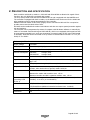
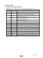
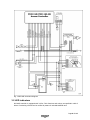
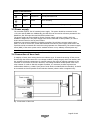
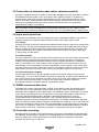
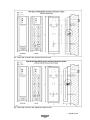
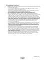
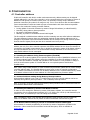
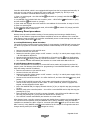
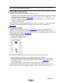
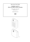
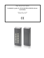
Roger Access Control System
Installation guide for PR311SE/PR311SE-BK Access
Controllers
Firmware version: 1.16.1255
Document version: Rev. F
Contents
1. Introduction ................................................................................................................. 3
1.1 This manual ..................................................................................................................... 3
1.2 Typing conventions........................................................................................................... 3
2. Description and specification ....................................................................................... 4
3. Installation .................................................................................................................. 5
3.1
3.2
3.3
3.4
3.5
3.6
Wires and connection diagram ........................................................................................... 5
LED indicators .................................................................................................................. 6
Power supply ................................................................................................................... 7
Connection of door lock .................................................................................................... 7
Connection of external reader and/or extension module....................................................... 8
Input and output lines ...................................................................................................... 8
3.6.1 Inputs ......................................................................................................................... 8
3.6.2 Relay outputs .............................................................................................................. 8
3.6.3 General purpose outputs .............................................................................................. 8
3.7 RS485 communication bus ................................................................................................ 8
3.8 Controller mounting .......................................................................................................... 8
3.8 Installation guidelines ..................................................................................................... 10
4. Configuration ............................................................................................................. 11
4.1
4.2
4.3
4.4
Controller address .......................................................................................................... 11
Memory Reset procedure ................................................................................................ 12
Controller programming .................................................................................................. 13
Firmware update ............................................................................................................ 13
5. Ordering information ................................................................................................. 14
Page 2 of 14
1. INTRODUCTION
1.1 This manual
This manual contains minimum information that is necessary to properly install the devices and to
perform initial tests. Full functional description of the controllers and set of commands for manual
programming have been included in the document – PRxx1 series access controllers functional
description, which is available at www.roger.pl.
If PR311SE and PR311SE-BK controllers are not clearly distinguished in particular paragraph, then
information specified for PR311SE are also valid for PR311SE-BK. But if PR311SE-BK name is used
in particular paragraph then the information concerns only that specific type of controller.
1.2 Typing conventions
Examples
italics letters
Specific names related to RACS
system
with first capital letter
Notes
separated with two lines (upper, lower) from the standard text
Page 3 of 14
2. DESCRIPTION AND SPECIFICATION
Both controllers with built-in readers i.e. PR311SE and PR311SE-BK are identical in regard of their
functions, but only PR311SE is equipped with keypad.
The new, factory-made controller has the address ID=00 and is equipped with the MASTER card.
The controller is equipped with built-in reader, so the MASTER card can be used for the initial tests
after installation and for manual programming of the controller.
Additional external reader of PRT series (Roger) can be connected to PR311SE if it is required to
provide access control at both sides of door.
PR311SE can be installed both outdoors and indoors and does not require special protection against
rain and moisture.
The controller can be programmed by means of computer with PR Master software or manually by
means of command entered with keypad. PR311SE-BK, which is not equipped with keypad can also
be programmed manually but in such case connection of external reader of PRT series with keypad
is necessary. PR311SE can be connected to PC by means of communication interface i.e. UT-2, UT2USB, UT-4 or RUD-1.
Table 1. Specification
Supply voltage
10-15VDC
Proximity cards
EM 125 kHz (UNIQUE), in accordance with EM4100/4102
Reading distance
Up to 15 cm for ISO cards (depends on card type and quality)
Current consumption
PR311SE:
average 70mA
PR311SE-BK:
average 50mA
Tamper
Isolated contact, NC type, 24V/50 mA rated
Input lines IN1…IN3
NO/NC inputs, electrically biased to +12V via 15 kΩ resistor, triggering level
app. 3.5V
Output REL1
Relay output with single NO/NC contact, 30V/1.5A max. load
Output lines IO1/IO2
Open collector transistor outputs, internally biased to +12V via 15 kΩ
resistor, when active short to ground, rated 15VDC/1A
Distances
RS485 comm. bus: up to 1200m
Between the reader and controller: max. 150 m
Between controller and XM-2 expansion module: max. 150 m
Environmental class
(according to EN
50131-1)
Class IV, outdoor general conditions, temperature: -25°C to +60°C, relative
humidity: 10 to 95% (no condensation)
Dimensions HxWxD
152,5x46x23mm (standard enclosure base)
152,5x46x35mm (additional extended enclosure base - included)
Weight
approx. 150g
Certificates
CE
Page 4 of 14
3. INSTALLATION
3.1 Wires and connection diagram
PR311SE controller is equipped with 45 cm connection cable including following wires.
Table 2. Wires
Name
Colour
Description
+12V
Red
Positive power supply contact, 12V DC
GND
Black
Negative power supply contact and reference potential for RS485
communication bus, input lines and CLK/DTA interface
IN1
Pink
IN1 input line, internally connected to the power supply plus
(+12V) through a 5.6kΩ resistor
IN2
Blue
IN2 input line, internally connected to the power supply plus
(+12V) through a 5.6kΩ resistor
IN3
White-yellow
IN3 input line, internally connected to the power supply plus
(+12V) through a 5.6kΩ resistor
RS485 A
Brown
RS485 communication bus
RS485 B
Green-white
RS485 communication bus
CLK
White
RACS communication bus (external reader, modules)
DTA
Green
RACS communication bus (external reader, modules)
TMP A
Grey
Anti-sabotage contact, line A, rated 24V/50mA
TMP B
Yellow
Anti-sabotage contact, line B, rated 24V/50mA
IO1
Yellow-brown
IO1 transistor output of open collector type, rated 15V DC/1.0A
IO2
Green-brown
IO2 transistor output of open collector type, rated 15V DC/1.0A
REL1-NC
Grey-pink
REL1 relay output, contact normally closed, rated 30V/1.5A
REL1-COM
Red-blue
REL1 relay output, common contact, rated 30V/1.5A
REL1-NO
Violet
REL1 relay output, contact normally opened, rated 30V/1.5A
Page 5 of 14
Fig. 1 PR311SE connection diagram
3.2 LED indicators
PR311SE controller is equipped with 3 LEDs. Their functions and colours are specified in table 3
below. Functioning of LEDs can be verified by means of included MASTER card.
Page 6 of 14
Table 3. LED indicators
Symbol
Name
Colour
Description
STATUS
Red/Green
Armed/disarmed mode
OPEN
Green
Door unlocking
SYSTEM
Orange
Various system functions and programming
3.3 Power supply
The controller requires 12V DC nominal power supply. The power should be connected to the
+12V wire and the GND wire. Additionally, the GND wire can be used as reference potential for the
RS485 bus, IN1-IN3 input lines and CLK/DTA interface lines.
The power supply can be provided by means of power supply unit PS10 or PS20, which are
available in Roger offer. The power supply units can be connected to backup battery in order to
ensure access control in case of power failure.
All devices connected to RS485 bus (including controllers) should have common supply minus
(GND). In order to ensure this, all the GND terminals from various power supply units used in the
system should be connected with each other using separate wire. Alternatively, the common supply
minus (GND) of the entire system can be earthed however in one, arbitrary selected point only.
Note: Do not connect positive terminals of power supply units with each other within the system.
3.4 Connection of door lock
In majority of cases, door locking devices are inductive type. It means that turning off the current
flow through the device causes the over voltage condition (voltage surges) which can interfere with
the controller electronic components. In extreme cases it may result in improper operation of the
controller or even freeze of the unit. Moreover, overvoltage condition causes quicker wear of the
relay contacts. In order to limit this negative condition, it is necessary to utilize a general use
semiconductor diode e.g. 1N4007 (one piece of such diode is included with the controller). It should
be connected as close as possible to the inductive element (electric strike or magnetic lock).
Fig. 2 Connection of door lock
Page 7 of 14
3.5 Connection of external reader and/or extension module
PR311SE is equipped with built-in reader for EM 125kHz (UNIQUE) proximity cards and can operate
with additional external reader of PRT series and/or XM-2 extension module. The address of
external reader must be ID=0 (factory default address of PRT reader) and the address of XM-2
must be ID=5. Both mentioned device should be connected to CLK and DTA wires. Any type of
cables (e.g. unshielded twisted pair) can be used for CLK and DTA lines. The guaranteed
communication distance is 150 meters.
Note: Practically, devices communicating in RACS CLK/DTA standard (e.g. PRT readers) can be
connected to the controller for distances up to 500m, but it is not guaranteed by the manufacturer.
3.6 Input and output lines
The functions are assigned to input and outputs by means of PR Master software or by means of
command entered with keyboard. Default function for REL1 relay output is door unlock.
3.6.1 Inputs
All inputs (IN1-IN3) of PR311SE controller have identical electric structure and can be configured as
NO or NC lines. The NO input is triggered by shorting it to supply minus (GND) while the NC input
must be normally shorted to supply minus (GND) and it becomes triggered when connection with
ground is discontinued. Every input is internally connected (pulled up) to the power supply plus
(+12V) through a 15kΩ resistor.
3.6.2 Relay outputs
The relay output REL1 offers one switched contact rated 30V/1.5A. The relay contacts are internally
protected against overvoltage by semiconductor elements. However this does not release the
installer from responsibility to eliminate interferences from inductive elements by an additional
diode. It is forbidden to use relay output to switch voltages above 30V because this for sure will
cause damage to the semiconductor elements protecting the relay’s contacts. In the normal state
(the relay is off) the NC-COM contacts are shorted. In the triggering state (the relay is on) the NOCOM contacts are shorted. In case of lack of the power, the REL1 output is in the off state.
3.6.3 General purpose outputs
Two transistor outputs (IO1, IO2) are available in PR311SE controller. All these lines are open
collector type, i.e. in the normal (off) state are pulled to supply plus via 15kΩ resistor and when on,
they short to supply minus. Both lines can switch current up to 1A DC while voltage connected to
the output must not exceed 15VDC. In case of overcurrent state, transistor outputs are
automatically switched off and the controller automatically restarts.
3.7 RS485 communication bus
The RS485 bus consists of two signal lines A and B. In the RACS 4 system any topology can be
used (star, tree or any combination of them, except for loop) in order to connect controllers in
subsystem and to establish access control system. The matching resistors (terminators) connected
at the ends of transmitting lines are not required. In most cases communication works with any
cable type (standard telephone cable, shielded or unshielded twisted pair etc.) but the
recommended cable is unshielded, twisted pair (UTP). Shielded cables should be limited to
installations subject to strong electromagnetic interferences. The RS485 communication standard
used in the RACS 4 system guarantees proper communication in a distance of up to 1200 meters as
well as high resistance to interferences. For the communication in longer distances it is required to
use UT-3 or UT-4 interface. A pair of UT-3 interfaces increases communication distance by another
1200 m while in case of UT-4 interface it is possible to communicate through LAN or WAN.
3.8 Controller mounting
PR311SE enclosure consists of front panel and base. New device is assembled with standard base,
but additional, extended base in included. The extended base can be used when connection cable
has to be hidden and no flush mounting box is available. Reference dimensions of PR311SE
controller are shown in fig. 3 and fig. 4.
Page 8 of 14
Fig. 3 PR311SE controller with standard enclosure base
Fig. 4 PR311SE controller with additional enclosure base
Page 9 of 14
3.8 Installation guidelines
· Install devices in such way as to ensure easy access to wires/terminals and jumpers (RST, FDM)
located inside the controller.
· Prior to controller installation it is recommended to set its address (ID number) – see 4.1
Controller address. Factory default address is ID=00.
· The controller is delivered with MASTER proximity card, however any proximity card in EM
125kHz (UNIQUE) standard can be programmed as MASTER card.
· The controller should be installed at vertical wall in vicinity of controlled door.
· All electric cables must be connected to devices with disconnected power supply.
· All devices within RACS 4 system (controllers, readers, extension modules) should have
common supply minus (GND). In order to ensure this, all the GND terminals from various power
supply units used in the system (including access controllers with built-in power modules)
should be connected with each other using separate wire. Alternatively, the common supply
minus (GND) of the entire system can be earthed however in one, arbitrary selected, point only.
· A silicone diode of general use e.g. 1N4007 should be always connected in parallel to the door
locking device (magnetic lock, electric strike, relay coil) — one piece of such diode is delivered
with the controller. It should be connected as close as possible to the inductive element.
· It is recommended to supply door locking device by means of separate wires, directly
connected to power supply unit.
· It is recommended to install controllers/readers in minimal distance of 0,5m from each other.
· Because of relatively low magnetic field, the reader should not interfere with other devices,
however its operation can be disrupted by devices generating a strong electromagnetic field.
· If the range of card reading is significantly lower than specified in technical documentation,
consider relocation of controller/reader.
· Readers can be installed on metal surfaces but in such case reduction of reading distance
should be expected. The reading distance reduction effect can be minimized by installing
readers on the non-metal spacer with minimal thickness of 10 mm (e.g. PVC). If two readers
have to be installed on opposite sides of the same wall, it is recommended that they are not
directly opposite (in the same axis).
· In case of installation on rough surface (porous) it is recommended to use metal spacer AX-1
(Roger). The spacer can be also used as electromagnetic screen, which prevents cross
interferences of controllers/readers. Installation of AX-1 may result in reduction of reading
distance by approx. 20%, which in many installations is fully acceptable..
Page 10 of 14
4. CONFIGURATION
4.1 Controller address
If PR311SE controller with built-in reader works autonomously, address setting can be skipped
(default address ID =00) but if the controller is to be connected with other controllers by means of
RS485 bus and operate in network system, then it is necessary to assign unique address to
particular controllers (ID number from range 00..99). Two or more devices with the same address
cause communication conflict and make a proper communication with these devices impossible.
There are four methods of setting controller address:
· During update of controller firmware by means of Roger ISP software (so called Fixed ID)
· Manually, during Memory Reset procedure
· By means of PR Master software
· Manually, by means of commands entered with keypad
The first method is called hardware address and the remaining ones are called software addresses.
The main difference between these two addressing methods is that software addresses can be
changed in all possible ways while hardware address can be changed only during firmware update.
Fixed ID has the highest priority and the other methods have lower priority.
Note: A new controller can be connected to the existing system without the necessity to change its
address, but only if no other controller operates with default address ID=00. Once the controller is
connected to the RS485 communication bus, it should be detected by means of PR Master software
and required address can be set. It is recommended to assign addresses to all controllers as to
make default address ID=00 unoccupied.
4.1.1 Setting the address during firmware update (Fixed ID)
FixedID can be set during update of the controller firmware by means of ROGER ISP software. Prior
to firmware upload, Roger ISP software offers the possibility to set Fixed ID address in range of
00..99. Once the FixedID is selected and uploaded to the controller it is not possible to change it
until the next firmware update. If FixedID address in not required operator should select
FixedID=None.
Note: When using FixedID address no other method except firmware update can be used to change
controller address again. The FixedID address is saved even in case of controller configuration
error. Thanks to this feature controller can be always detected on the communication bus by means
of PR Master software with the same address as it was assigned during firmware update.
4.1.2 Manual address setting during Memory Reset procedure
When hardware address is not used (i.e. FixedID=None) then the controller address can be set
manually during Memory Reset procedure – see 4.2 Memory Reset procedure.
Note: If controller works with Fixed ID then Memory Reset procedure can be executed but still the
new software address shall not be effective.
4.1.3 Setting the address by means of PR Master software
In order to set or change the address by means of PR Master software, the controller must be
connected to PC via communication interface (UT-2, UT-2USB, UT4 or RUD-1) and detected by the
software. Once, it is detected you can use Change ID command.
Note: The address, which is set manually during Memory Reset procedure can be changed by
means of PR Master software and by means of manual commands entered with keypad.
4.1.4. Manual address setting by means of commands entered with keypad
All commands for manual programming of controller by means of keypad are specified in the
document – PRxx1 series access controllers functional description, which is available at
www.roger.pl.
Page 11 of 14
Controller PR311SE-BK, which is not equipped with keypad can also be programmed manually. In
such case it is just enough to connect PRT series reader with keypad (e.g. PRT12) to such
controller. Procedure of manual address setting is as follows:
shall switch on (orange) and LED OPEN
shall
1. Enter 01# with keypad – the LED SYSTEM
switch on (green).
2. Use MASTER card (included with the controller) twice – LED STATUS
shall switch on (red)
and LED SYSTEM
shall switch on (orange).
3. Enter 40XX with keypad, where XX means the new address of the controller in range of 00-99
4. Enter 00# with keypad.
5. The controller shall return to normal mode, LED SYSTEM
shall switch off (orange) and LED
STATUS
shall remain switched on.
4.2 Memory Reset procedure
Memory Reset procedure enables erasing of current settings and returning to default factory
settings. It also allows to program new Master card/PIN as well as new address of the controller.
After Memory Reset procedure, the controller automatically enters normal working mode and is set
in Armed Mode (LED STATUS
is red).
4.2.1 Simplified Memory Reset Procedure
This method erases controller memory and allows for programming of MASTER card however does
not allow to program the controller address (address is automatically set to ID=00) nor MASTER
PIN.
· Remove connections to CLK and DTA wires
· Connect CLK wire with DTA wire
· Restart the controller (place jumper on RST contacts – see fig. 5 or switch power supply off/on)
– all LED indicators shall be on
· Disconnect CLK and DTA wires— the LEDs shall be off, and then LED (green) shall pulsate
· While the LED is pulsing, read any card at the controller — this will be a new MASTER card
· The controller restarts automatically and switches to normal mode with address ID=00
4.2.2 Full Memory Reset procedure
In case of PR311SE-BK it is necessary to connect PRT series reader with keypad to perform full
memory reset. Full Memory Reset allows for programming of new MASTER identifier (card and/or
PIN) and setting controller ID address.
· Remove connections to CLK and DTA wires
· Connect CLK wire with DTA wire
· Restart the controller (place jumper on RST contacts – see fig. 5 or switch power supply off/on)
– all LED indicators shall be on
· Disconnect CLK and DTA terminals— the LEDs shall be off, and then LED OPEN (green) shall
pulsate
· In case of PRT311SE-BK connect PRT series reader with keypad to CLK and DTA lines and
execute further steps by means of that reader. In case of PR311SE, which is equipped with
keypad, use that keypad in further steps
· Enter new MASTER PIN (3-6 digits) followed with the [#] key or skip this step just pressing the
[#] key
· Read any card at the controller/reader — this will be a new MASTER card or skip this step just
pressing the [#] key
· Enter two digits (in range of 00-99) by means of keypad – this will be new ID address or skip
this step just pressing the [#] key and then default ID=00 shall be set
· The controller restarts automatically and switches to normal mode
After Memory Reset, controller resumes its work with default factory settings and entered address.
You can then test its operation using the MASTER card or PIN (if available). Using the MASTER
card/PIN once activates the REL1 output for 4 seconds (LED OPEN
lights up for the time when
REL1 is active). Using MASTER card/PIN twice switches the IO1 output to the opposite state and
changes its colour).
changes arming mode (LED STATUS
Page 12 of 14
Note: If the controller address is hardware type (see 4.1 Controller address) then address set
during Memory Reset procedure is ignored.
4.3 Controller programming
PR311SE settings can be entered based on following methods:
· By means of PR Master software, which has to be installed on computer. The computer must be
connected to the controller by means of communication interface (e.g. UT-2USB, RUD-1, UT-4).
PR Master software is available at www.roger.pl.
· By means of command entered with keypad (in case of PR311SE-BK it is required to connect
any PRT series reader with keypad).
· By means of Function Cards.
More information on controller programming can be found in the document – PRxx1 series access
controllers functional description and in PR Master User Manual, which are available at
www.roger.pl.
4.4 Firmware update
The latest version of firmware is available at www.roger.pl. In order to update firmware it is
necessary to connect the device by means of RS485 bus to communication interface (UT-2, UT2USB, UT4 or RUD-1) and then connect the interface to PC with installed Roger ISP software. Roger
ISP is available free of charge at www.roger.pl.
Firmware update procedure
·
·
Connect power supply to the device
Place jumper on FDM contacts
Fig. 5 Location of FDM and RST contacts inside the enclosure of PR311SE controller
·
·
·
Reset the device (place jumper on RST contacts or switch power off/on)
Start RogerISP software and select communication port (in case of RUD-1 select RS-485).
In Firmware window select firmware file (can be downloaded from www.roger.pl) and then
select Program option.
· After firmware upload, remove jumper from FDM contacts and reset the device.
In case of network system, it is required to restart controller within PR Master software by right
clicking particular controller and selecting the option – Restart controller and verify version.
Page 13 of 14
5. ORDERING INFORMATION
Table 4. Ordering information
PR311SE
Access controller of standard PRxx1 series with built-in EM 125 kHz (UNIQUE) card
reader and with keypad, standard version with connection cable
PR311SEBK
Access controller of standard PRxx1 series with built-in EM 125 kHz (UNIQUE) card
reader and without keypad, standard version with connection cable
PRT12-LT
EM125 kHz (UNIQUE) card reader
XM-2-BRD
Input/output addressable extension module, which provides two NO/NC inputs and
two relay outputs with single switched contact NO/NC rated 30V/1.5A.
Communication with host device can be performed using CLK/DTA lines. The module
can be located in a distance of 150 m from the host device (controller).
RM-2
Module with two relay outputs, rated 30V/1.5A each with single switched contact
NO/NC. Relays can be triggered by applying low or high voltage signal. Triggering of
relay is indicated by LED on the module’s board.
UT-4
Communication interface: Ethernet-RS485.
UT-2USB
Communication interface: USB-RS485.
UT-2
Communication interface: RS232-RS485.
RUD-1
Portable communication interface USB-RS485 with 12VDC output, which can supply
connected controller.
This symbol placed on a product or packaging indicates that the
product should not be disposed of with other wastes as this may
have a negative impact on the environment and health. The user is
obliged to deliver equipment to the designated collection points of
electric and electronic waste. For detailed information on recycling,
contact your local authorities, waste disposal company or point of
purchase. Separate collection and recycling of this type of waste
contributes to the protection of the natural resources and is safe to
health and the environment. Weight of the equipment is specified
in the document.
Contact:
Roger sp.j.
82-400 Sztum
Gościszewo 59
Tel.: +48 55 272 0132
Fax: +48 55 272 0133
Tech. support: +48 55 267 0126
E-mail: [email protected]
Web: www.roger.pl
Page 14 of 14