1
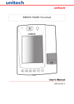
unitech
Unitech MR650
Product Reference Guide
Preface
About This Manual
This manual explains how to install, operate and maintain the MR650 TAS Terminal.
No part of this publication may be reproduced or used in any form, or by any electrical
or mechanical means, without permission in writing from the manufacturer. This includes
electronic or mechanical means, such as photocopying, recording, or information
storage and retrieval systems. The material in this manual is subject to change without
notice.
© Copyright 2007 Unitech Electronics Co., Ltd. All rights reserved.
Microsoft, Windows and ActiveSync are either registered trademarks or trademarks
of Microsoft Corporation. Other product names mentioned in this manual may be
trademarks or registered trademarks of their respective companies and are hereby
acknowledged.
Regulatory Compliance
CE, FCC, BSMI
Warranty
• Terminal is covered by a 1-year limited warranty
• Cables are covered by a 1-year limited warranty
• Backup battery is covered by a 3-month limited warranty
Notices
The Unitech MR650 is equipped with a Lithium-Ion battery pack, however as a result
of storage it’s possible that the unit will not power-on due to battery discharge. If this
occurs, connect the MR650 to the power adapter and plug into a standard electrical
outlet. Recharge the unit for 22 hours in order to fully charge its backup battery.
The battery pack can power the MR650 for approximately 2 hours (depending upon
hardware configuration and limited backlight), and backup data will remain for 3 days in
the absence of external power.
Battery Charge Notice
It is important to consider the environment temperature whenever you are charging
the Lithium-Ion battery pack. The process is most efficient where the temperature
is average or slightly cooler. It is essential that you charge the batteries within the
specified range of -5°C to 50°C. Charging batteries outside of the specified range could
damage the batteries and shorten their charging life cycle.
Storage and Safety Notice
Although charged Lithium-Ion batteries may be left unused for several months, their
capacity may deplete due to build up of internal resistance. If this occurs, the battery
will require recharging prior to use. Lithium-Ion batteries may be stored at temperatures
between-20°C to 60°C, however they may deplete more rapidly at the high end of this
range. It is recommended batteries are stored within normal room temperature ranges.
ii
Table of Contents
Preface
About This Manual
Regulatory Compliance. . . . . . . . . . . . . . . . . . . . . . . . . . . . . . . . . . . . . . . . . . . . i
Warranty . . . . . . . . . . . . . . . . . . . . . . . . . . . . . . . . . . . . . . . . . . . . . . . . . . . . . . . . i
Notices. . . . . . . . . . . . . . . . . . . . . . . . . . . . . . . . . . . . . . . . . . . . . . . . . . . . . . . . . ii
Battery Charge Notice . . . . . . . . . . . . . . . . . . . . . . . . . . . . . . . . . . . . . . . . . . . ii
Storage and Safety Notice . . . . . . . . . . . . . . . . . . . . . . . . . . . . . . . . . . . . . . . ii
Chapter 1
Getting Started
Introducing the MR650. . . . . . . . . . . . . . . . . . . . . . . . . . . . . . . . . . . . . . . . . . . . . . . . . 7
Support . . . . . . . . . . . . . . . . . . . . . . . . . . . . . . . . . . . . . . . . . . . . . . . . . . . . . . . . . . . . 8
Features . . . . . . . . . . . . . . . . . . . . . . . . . . . . . . . . . . . . . . . . . . . . . . . . . . . . . . . . . . . . 9
Package Contents. . . . . . . . . . . . . . . . . . . . . . . . . . . . . . . . . . . . . . . . . . . . . . . . . . . . 10
A Tour of the MR650 . . . . . . . . . . . . . . . . . . . . . . . . . . . . . . . . . . . . . . . . . . . . . . . . . . 11
Front View . . . . . . . . . . . . . . . . . . . . . . . . . . . . . . . . . . . . . . . . . . . . . . . . . . . . . . . . 11
Back View . . . . . . . . . . . . . . . . . . . . . . . . . . . . . . . . . . . . . . . . . . . . . . . . . . . . . . . . 12
First Steps with MR650. . . . . . . . . . . . . . . . . . . . . . . . . . . . . . . . . . . . . . . . . . . . . . . . 13
Supply Power to MR650. . . . . . . . . . . . . . . . . . . . . . . . . . . . . . . . . . . . . . . . . . . . . . . 14
Protective Screen Film. . . . . . . . . . . . . . . . . . . . . . . . . . . . . . . . . . . . . . . . . . . . . . . . 15
Power on MR650. . . . . . . . . . . . . . . . . . . . . . . . . . . . . . . . . . . . . . . . . . . . . . . . . . . . . 15
Calibrate the MR650 . . . . . . . . . . . . . . . . . . . . . . . . . . . . . . . . . . . . . . . . . . . . . . . . . . 15
Setting the Time Zone/Date . . . . . . . . . . . . . . . . . . . . . . . . . . . . . . . . . . . . . . . . . . . . 16
Setting the Time Zone . . . . . . . . . . . . . . . . . . . . . . . . . . . . . . . . . . . . . . . . . . . . . . . 16
Setting the Date/Time . . . . . . . . . . . . . . . . . . . . . . . . . . . . . . . . . . . . . . . . . . . . . . . 17
iii
Chapter 2
Using the Hardware
Using the Keypad & Reader. . . . . . . . . . . . . . . . . . . . . . . . . . . . . . . . . . . . . . . . . . . . 18
Rubber Keypad . . . . . . . . . . . . . . . . . . . . . . . . . . . . . . . . . . . . . . . . . . . . . . . . . . . . 18
Software Keyboard. . . . . . . . . . . . . . . . . . . . . . . . . . . . . . . . . . . . . . . . . . . . . . . . . . . 19
Open Windows CE Keyboard . . . . . . . . . . . . . . . . . . . . . . . . . . . . . . . . . . . . . . . . . 19
Key-in Character . . . . . . . . . . . . . . . . . . . . . . . . . . . . . . . . . . . . . . . . . . . . . . . . . . . 19
International Character Support. . . . . . . . . . . . . . . . . . . . . . . . . . . . . . . . . . . . . . . . 19
Moving Keyboard . . . . . . . . . . . . . . . . . . . . . . . . . . . . . . . . . . . . . . . . . . . . . . . . . . . 19
Closing the Keyboard. . . . . . . . . . . . . . . . . . . . . . . . . . . . . . . . . . . . . . . . . . . . . . . . 19
Using the Readers. . . . . . . . . . . . . . . . . . . . . . . . . . . . . . . . . . . . . . . . . . . . . . . . . . . . 20
Using Proximity/MSR/Barcode. . . . . . . . . . . . . . . . . . . . . . . . . . . . . . . . . . . . . . . . . 20
Testing Reader’s Data. . . . . . . . . . . . . . . . . . . . . . . . . . . . . . . . . . . . . . . . . . . . . . . 20
Using Finger Print Reader. . . . . . . . . . . . . . . . . . . . . . . . . . . . . . . . . . . . . . . . . . . . 21
Testing Fingerprint Verification . . . . . . . . . . . . . . . . . . . . . . . . . . . . . . . . . . . . . . . . . 22
Enroll Fingerprint Stamp . . . . . . . . . . . . . . . . . . . . . . . . . . . . . . . . . . . . . . . . . . . . . 23
Verify Fingerprint Stamp. . . . . . . . . . . . . . . . . . . . . . . . . . . . . . . . . . . . . . . . . . . . . . 24
Using Camera . . . . . . . . . . . . . . . . . . . . . . . . . . . . . . . . . . . . . . . . . . . . . . . . . . . . . . . 25
Testing the Camera . . . . . . . . . . . . . . . . . . . . . . . . . . . . . . . . . . . . . . . . . . . . . . . . . 26
Chapter 3
Power System
Charging Backup Battery for the First Time . . . . . . . . . . . . . . . . . . . . . . . . . . . . . . . 27
Environment Consideration for Charging . . . . . . . . . . . . . . . . . . . . . . . . . . . . . . . . . 27
Power status indication . . . . . . . . . . . . . . . . . . . . . . . . . . . . . . . . . . . . . . . . . . . . . . 27
Backlight Setting . . . . . . . . . . . . . . . . . . . . . . . . . . . . . . . . . . . . . . . . . . . . . . . . . . . . . 28
Screen Contrast. . . . . . . . . . . . . . . . . . . . . . . . . . . . . . . . . . . . . . . . . . . . . . . . . . . . 28
Screen Backlight . . . . . . . . . . . . . . . . . . . . . . . . . . . . . . . . . . . . . . . . . . . . . . . . . . . 28
Warm Start/ Cold Start . . . . . . . . . . . . . . . . . . . . . . . . . . . . . . . . . . . . . . . . . . . . . . . . 29
Chapter 4
Data Communication
Connecting. . . . . . . . . . . . . . . . . . . . . . . . . . . . . . . . . . . . . . . . . . . . . . . . . . . . . . . . . . 30
Serial Cable. . . . . . . . . . . . . . . . . . . . . . . . . . . . . . . . . . . . . . . . . . . . . . . . . . . . . . . 30
Ethernet Cable . . . . . . . . . . . . . . . . . . . . . . . . . . . . . . . . . . . . . . . . . . . . . . . . . . . . . 30
RF Communication . . . . . . . . . . . . . . . . . . . . . . . . . . . . . . . . . . . . . . . . . . . . . . . . . 31
Use ActiveSync. . . . . . . . . . . . . . . . . . . . . . . . . . . . . . . . . . . . . . . . . . . . . . . . . . . . . . 32
iv
Chapter 5
Useful Utilities
Scanner Setting . . . . . . . . . . . . . . . . . . . . . . . . . . . . . . . . . . . . . . . . . . . . . . . . . . . . . . 33
Scan2Key . . . . . . . . . . . . . . . . . . . . . . . . . . . . . . . . . . . . . . . . . . . . . . . . . . . . . . . . . . . 33
Registry Backup/Restore. . . . . . . . . . . . . . . . . . . . . . . . . . . . . . . . . . . . . . . . . . . . . . 34
Audio Demo Program. . . . . . . . . . . . . . . . . . . . . . . . . . . . . . . . . . . . . . . . . . . . . . . . . 35
Softkeys . . . . . . . . . . . . . . . . . . . . . . . . . . . . . . . . . . . . . . . . . . . . . . . . . . . . . . . . . . . 36
Chapter 6
Terminal Block
Over view of Terminal Block. . . . . . . . . . . . . . . . . . . . . . . . . . . . . . . . . . . . . . . . . . . . 37
Terminal Block Pin Assignment . . . . . . . . . . . . . . . . . . . . . . . . . . . . . . . . . . . . . . . . . 38
Chapter 1 Getting Started
Chapter 1
Getting Started
Introducing the MR650
The MR650 is a TAS (Time Management, Access Control and Security) Terminal
with a large 240 x 320 pixel color touch screen, and uses the familiar interface Windows
CE 5.0 Operating System. Unitech’s MR650 is designed to meet the requirements
of Time & Attendance, Loyalty Programs and Work-In-Process applications. Users
can increase productivity right from the start and application development is easier
than ever. The unit can communicate with central host security and T&A systems via
standard Ethernet or WLAN networks. The MR650 also provides the ability to seize
complete control over area security with a built-in CMOS digital camera, microphone,
and audio speaker. Multiple I/O ports and interfaces make it the ideal solution for
complex systems. The MR650 features a variety of built-in readers such as proximity
and finger print, giving the user the ability to choose the technology that best fits their
needs and budget.
Chapter 1 Getting Started
Support
Unitech’s professional support team is available to quickly answer your questions or
technical-related issues. Should an equipment problem occur, please contact the
Unitech regional service representatives nearest you. Please go to their websites, listed
below, for complete contact information:
UTC (China) http://www.ute.com.cn
UTT (Taipei, Taiwan) http://www.unitech.com.tw
APAC (Taipei, Taiwan) http://www.unitech-adc.com
UTJ (Japan) http://www.unitech-japan.co.jp
UTA (USA, Canada) http://www. ute.com
UTA (Latin America) http://www.latin.ute.com
UTI (Europe) http://www.unitech-europe.nl
Features
System
• Microsoft Windows CE 5.0
Professional Operating System
• Intel PXA270 520MHz Processor
System Memory
• 128MB RAM
• 64MB FlashROM
Display
• 5.6” QVGA LCD color touch
screen
• 240 x 320 resolution
Input / Output
• 6-key rubber keypad
• 0.8W audio speaker
• Microphone input
• 1.3 mega pixel CMOS camera
Interface Ports
• Built-in RJ45 Ethernet Port
• USB host
• Optional POE module
• SD slot for additional memory
(Up to 2GB)
• CF Type II slot for wireless
connectivity (802.11 b/g)
• 3 output relays
• 4 digital inputs
Barcode Reader
• Unitech decoder chip
• Supports: China Postal Code,
Codabar, Code 11, Code 32,
Code 39, Code 93, Code 128,
Delta Code Interleaved 2 of 5,
ISBT 128, Label Code IV,
Label Code V, MSI, Standard 2 of 5,
Toshiba Code, UPC/EAN
Fingerprint Reader
• AuthenTec AFS8500 Sensor
• 2 second max verification time
• 0.1% Equal Error Rate
(at medium security)
• 4000 templates
Proximity Card Reader
• EM 125 kHz
• HID 125 kHz
Magnetic Stripe Reader
• Triple track
• 19 cm/sec tap speed
• 300,000 minimum passes
Power Management
• External 12V DC adapter
• Rechargeable Lithium-Ion UPS
battery
(3.8V, 4000 mAh) supports 2 hours
operation or 3 days data backup
Chapter 1 Getting Started
Package Contents
After opening the box, ensure the following items for the MR650 are present:
Unitech MR650
Quick Start Guide
MR650 Main Body
Manual CD
Stylus
RS232 Cable
AC Power Adapter
10
Chapter 1 Getting Started
A Tour of the MR650
The following sections describe the main components and features of the MR650.
Front View: Proximity/Biometric Reader (left), Slot Reader (right)
1
1
2
2
3
3
7
8
4
4
6
5
5
No.
Component
Description
1.
Speaker
Enables you to hear recorded audio.
2.
CMOS Camera
Allows photo to be captured when a card is read. Continuous
video recording capable.
3.
Microphone
Enables you to record voice audio.
4.
LCD Touch Screen
Displays the applications and data stored on your device. It is
touch sensitive and responds to the stylus or finger.
5.
Keypad
Keypad interface for controlling the MR650.
6.
Fingerprint Reader
Allows for verifying and enrolling fingerprint data.
7.
Proximity Reader
Capable of reading proximity cards.
8.
Slot Reader
Capable of reading barcodes or magnetic stripe cards.
11
Chapter 1 Getting Started
Back View
9
10
11
12
No.
Component
Description
9.
Front Case Hook
Connects the unit and the back panel.
10.
Terminal Block
Supplies DC power to main board.
11.
Mounting Hole
Allows for wall mounting.
12.
Key Lock
Gives access to internal circuit board.
12
Chapter 1 Getting Started
First Steps with the MR650
To power on the MR650, plug the 12V DC power adaptor into the DC Connector’s
Terminal Block, which is located on the inner side of the back panel. The MR650 can
operate while the backup battery is being charged. A full charge of the battery typically
takes 22 hours.
NOTE:
The UPS battery is used for standard operation when there is no main power supplied
and retains backup data for up to 3 days after power is lost. Therefore, data you enter
may not be properly stored until the built-in backup battery has been adequately
recharged.
13
Chapter 1 Getting Started
Supply Power to the MR650
Insert key into lock and turn
counter-clockwise to unlock
Plug 12V DC to terminal block and turn
battery switch on to charge battery
Lift back plate up 45˚ degrees
Push switch down to “on” position
14
Chapter 1 Getting Started
Protective Screen Film
The MR650 screen comes standard with a protective plastic film. You may remove it
if desired, by peeling from one corner. Without the protective film the screen will be
operable and readable, however it will be more susceptible to scratching.
Power On MR650
The MR650 will automatically power-on when the 12V DC power adapter is plugged in.
Calibrate the MR650
A screen will automatically appear when the unit is powered-on for the first time or
after the system is reset. The MR650 will prompt you to calibrate the unit by tapping
a sequence of screen locations. Tap gently but firmly. When you have completed the
series of taps, press the [ENT] key to confirm, or press the [ESC] key to cancel the
operation.
15
Chapter 1 Getting Started
Setting the Time Zone/Date
After calibrating the MR650, the “Date/ Time Properties” dialog box will appear.
Setting the Time Zone
Follow the steps below to set up your time zone.
1. Tap the location arrow to see a list of cities.
2. Choose your location (or nearest listed one).
3. Select the Daylight Savings Time check box, if necessary.
4. Tap the APPLY button.
16
Chapter 1 Getting Started
After calibrating the MR650, the “Date/ Time Properties” dialog box will appear.
Setting the Date/Time
Tap the left or right arrows to scroll the year and month you desire, or directly tap the
location of year or month to change the setting.
To set up the time, tap on the Hr/Min/Sec AM/PM as needed.
Exit Date/Time Properties Setting
Tap OK or X (cancel) button at upper-right corner to exit.
17
Chapter 2
Using the Hardware
Using the Keypad and Readers
Rubber Keypad
The MR650 keypad contains 6 rubber keys, including F1~F4, ESC and ENTER key.
Please refer to below picture.
[F1]~[F4] Standard Windows CE function key
[ESC] This key will perform the same function as tapping the CANCEL button or X
button on the touch screen.
[E] This key will perform the same function as tapping ENTER or OK button on the
touch screen.
18
Chapter 2 Using the Hardware
Software Keyboard
Since the MR650’s rubber keypad allows input of numeric characters only, the Windows
CE software provides a touch screen keyboard for input of other characters. The
windows based keyboard replicates the layout of a standard PC keyboard.
Open Windows CE Keyboard
The user can easily open the Windows CE keyboard by double tapping the “keyboard”
icon on the task bar. (Refer to below picture).
Key-in Character
After double tapping the “keyboard” icon, the Windows CE keyboard pops-up.
Character input is the same as a standard PC. Simply tap the on-screen button
corresponding to the character you want to input.
International Character Support
Tap the [áü] button to switch from the Standard English keyboard to the European
keyboard or switch from the standard keyboard to perform the desired special
characters.
Moving Keyboard
Use the stylus to point to the title bar (the bar
displaying “Input panel”). Then move the stylus
without lifting it from the screen.
Closing the Keyboard
To close Windows CE keyboard click Hide Input Panel.
19
Chapter 2 Using the Hardware
Using the Readers
The MR650 has an integrated Proximity
(EM125 kHz, HID 125 kHz, Mifare 13.56
MHz), MSR or Barcode reader which can
read all major barcode labels, magnetic
stripe card and EM 125 kHz, HID 125 kHz
proximity reader, 13.56 MHz Mifare reader
with excellent performance.
Place or swipe
the card here
Testing Reader’s Data
The MR650 has a built-in Scanner Settings.EXE program that allows the user to test
the reader’s data. To access the program go to the Start menu, locate the Control
Panel, double click the “Scanner Settings” icon, click on “Test”. The reading data will
appear on the screen.
20
Chapter 2 Using the Hardware
Using the Fingerprint Reader
The MR650 with the Fingerprint Reader
can hold up to 4000 templates. The
verifying time with the maximum amount
of templates will be less then 2 seconds.
Place finger here
21
Chapter 2 Using the Hardware
Testing Fingerprint Verification
The MR650 has a built-in BIOIDMgr.EXE program that allows the user to test the finger
print verification. The program is accessible via the “My Device” icon on the Windows
CE desktop. Locate the Windows folder, double click on the “BIOIDMgr” icon, the finger
print verification will appear on the screen. Click on “Is Finger”, place a finger on the
sensor, “finger is detected” message will appear. This means finger print function is
working properly.
22
Chapter 2 Using the Hardware
Enroll Fingerprint Stamp
Click on “Enroll”, enter an ID number for the fingerprint, click on “OK”, the message
“Place finger on sensor” will appear. Place the finger on the sensor and the fingerprint
will be tagged with a quality percentage and an ID number and will be saved in the
system.
23
Chapter 2 Using the Hardware
Verify Fingerprint Stamp
To verify a Fingerprint Stamp click on “Verify”, enter a fingerprint ID number, click on
“OK”, and the message, “Place finger on sensor” will appear. Place a finger on the
sensor to verify the fingerprint. The fingerprint’s quality percentage number will appear
on the screen with a “Pass” or “Fail” result.
24
Chapter 2 Using the Hardware
Using the Camera
The MR650 has a built-in 1.3 mega pixel camera, allowing a photo to be captured when
a card is read, documenting attendant time with a photo image. Continuous audio/video
recording is capable with the onboard camera and microphone.
1.3 mega pixel CMOS camera
25
Chapter 2 Using the Hardware
Testing the Camera
The MR650 has a built-in Camera Demo.EXE program that allows the user to see
the imager. The Camera Demo program is accessible via the “My Device” icon on
the Windows CE desktop. Locate the Windows folder, double click on the “Camera
Demo” icon, the testing program will appear on the screen. Click on “Start” located
in “Preview”, the continuous image will show on the screen, allowing you to view and
playback.
26
Chapter 3
Power System
Charging the Backup Battery for the First Time
The unit is equipped with a Lithium-Ion battery pack, however the unit may not power-on
without the external power adapter due to battery discharge. This is a result of a long
storage period. If this is the case, plug the unit into the power adapter and recharge unit
for about 22 hours to fully charge the battery.
Note:
The unit can operate for approximately 2 hours (depending on H/W configuration with
limited back light use) and backup data will be stored for 3 days after the external power
is off. More power is consumed when the backlight is used at 100% brightness and the
fingerprint function is in use. When the MR650 is out of external power the terminal
will go into sleeping mode and the backlight will turn off. Once the panel is touched the
backlight will be on minimum brightness to conserve power.
Environment Consideration for Charging
It is important to consider the environment temperature whenever you are charging
the Lithium-Ion battery pack. The process is most efficient where the temperature
is average or slightly cooler. It is essential that you charge the batteries within the
specified range of -5°C to 50°C. Charging batteries outside of the specified range could
damage the batteries and shorten their charging life cycle.
Power Status Indication
When there is no external power and the display indicates the backup battery is low,
plug the unit into the power adapter and immediately backup data.
27
Chapter 3 Power System
Backlight Setting
Screen Contrast
The MR650’s screen contrast has been set by the factory manufacturer and cannot be
adjusted by the end user.
Screen Backlight
The backlight for the color display is adjustable. To adjust the Backlight settings go to
the “My Device” icon on the Windows CE desktop and go to the Control Panel. Select
either of the two schemes – Battery Power or External Power.
Backlight Options
Dim Backlight
Turn Off Backlight
Turn On Backlight
Control
Select how many minutes you want to elapse before the
backlight dims.
Select how many minutes you want to elapse before the
backlight automatically turns off.
Select this option if you want the backlight to turn on
when the button is pressed or the touch screen is
tapped.
The backlight value can be adjusted by using the “On Intensity” and “Dim Intensity”
sliding bars.
28
Chapter 3 Power System
Warm Start / Cold Start
Warm Start
Warm Start re-boots the device without
losing SD RAM data. You would perform a
warm start when the following happens:
• The terminal fails to respond
• After installing some software
applications
• After making changes to certain
system settings, such as inserting a SD
card or CF card.
Cold Start
A cold start resets the operating system,
restores the terminal back to factory defaults, and resets the terminal after boot
loader, keyboard and kernel upgrade.
Cold start button
Warm start button
Warning
Performing a Warm Start will cause unsaved data to be lost.
Performing a Cold Start erases all of the data stored in the SD RAM memory and all
installed applications in RAM.
29
Chapter 4
Data Communication
The MR650 allows users to link to a host computer via RS232, Ethernet, or RF
connection for data communication.
Connecting
Serial Cable
Plug the RS232 communication cable into the PC’s 9 pin Com Port and the other end
into the MR650’s RS232 interface port.
Ethernet Cable
Plug the Ethernet cable into the PC’s Ethernet Port and connect the other end into the
MR650 Ethernet Port. There is an optional Power Over Ethernet (POE) module to
support the POE cable, which requires a POE Hub at the end user level.
RS232 connector
Ethernet connector
30
Chapter 4 Data Communication
RF Communication
Insert CF card for 802.11b/g wireless communication.
Windows CE can support TCP/IP protocol. The user can link to the Internet via the start
menu, under “Settings” then “Network and Dial-up Connections”.
Under “Network and Dial-up Connections”, go to DM9ISA1 to set up the IP to connect to
internet.
31
Chapter 4 Data Communication
Use ActiveSync
Using Microsoft ActiveSync, you can synchronize and transfer information between
your desktop computer and terminal. The most current version of ActiveSync can be
downloaded from www.microsoft.com.
Additional Capabilities
With ActiveSync, you can also:
• Back up and restore your device data.
• Copy (rather than synchronize) files between your device and desktop
computer.
• Control when synchronization occurs by selecting a synchronization mode.
For example, you can synchronize continually while connected to your
desktop computer or only when you choose the synchronize command.
• Select which information types are synchronized and control how much data is
synchronized. For example, you can choose how many weeks of past
appointments you want synchronized.
Requirements
To synchronize, ActiveSync version 4.1 or higher must be installed on both your
desktop computer and the MR650 terminal. The MR650 terminal ships with
ActiveSync already installed. Therefore, you must install ActiveSync 4.1 on your
desktop computer.
To install ActiveSync on your desktop computer, please link to Microsoft website
to get free download driver.
32
Chapter 5
Useful Utilities
Scanner Settings
When the user needs to change the
default barcode symbologies for a
different application the Scanner Control
Panel provides the setting function to
change default symbologies, place
delimiter characters behind scanned data,
and save the settings. To run the Scanner
Control Panel go to Start\Setting\Control
Panel\Scanner Setting.exe.
Scan2Key
The Scan2Key application sends data
from the scanner port to the keyboard
buffer, so that information captured from
a scanner, magnetic reader or proximity
reader will be treated as if input directly
from the keyboard. With this utility,
scanned data can be routed directly into
the keyboard buffer, like MS Pocket Word.
Scan2Key can be found under Start\
Settings\Control Panel\Scanner Setting\To
kpd
33
Chapter 5 Useful Utilities
Registry Backup/Restore
The Registry Backup/Restore program
gives the user the ability to save and
recall the initial changes made to Settings.
For example, if a cold boot was performed
the user can go to the Registry Backup to
retrieve the original settings.
Registry Restore is used to recall saved
backup settings. To run Registry Backup/
Restore go to Start\Program\Utilities\
RegBackup
34
Chapter 5 Useful Utilities
Audio Demo Program
The Audio Demo program allows you test audio input and output which can record and
playback voice recordings. The Audio Demo program is accessible via the “My Device”
icon on the Windows CE desktop. Locate the Windows folder, double click on the
“wavtest” icon, the testing program will appear on the screen. Click on “Rec” to record
the voice, click on “Stop” when done recording and click on “Play” to playback.
35
Chapter 5 Useful Utilities
Softkeys
Softkeys is the numeric on-screen keypad utility to input numeric keys. To run Softkeys
go to \Start\Program\Utilities\Softkeys.
36
Chapter 6
Terminal Block
Overview of Terminal Block
4 digital
inputs
12V DV
power in
3 relays
Flex cable to
main board
37
Chapter 6 Terminal Block
Terminal Block Pin Assignment
Pin
1
2
3
4
5
6
7
8
9
10
Name
GND
DC Out
DI1-L
D11-H
DI2-L
DI2-H
DI3-L
DI3-H
DI4-L
DI4-H
Description
GND
Support +12V, 0.5A
Photo-In Anode(-)
Photo in Cathode(+)
Photo-In Anode(-)
Photo in Cathode(+)
Photo-In Anode(-)
Photo in Cathode(+)
Photo-In Anode(-)
Photo in Cathode(+)
Pin
1
2
3
4
5
6
7
8
9
10
11
12
Name
DC In
GND
RY1-C
RY1-NC
RY1-NO
RY2-C
RY2-NC
RY2-NO
RY3-C
RY3-NC
RY3-NO
No Use
Description
+12V, 2A
GND
Common
Normal Close
Normal Open
Common
Normal Close
Normal Open
Common
Normal Close
Normal Open
No Use
1-------------------10
1-------------------12
Warning
This is a FCC Part 15 Class B product and in a domestic
environment this product may cause radio interface in which
case the user may be required to take adequate measures.
38