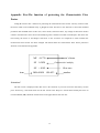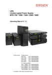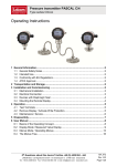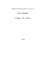
1
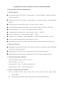
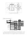
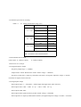
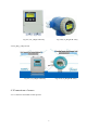
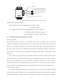
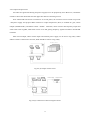
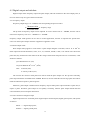
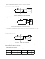
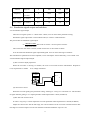
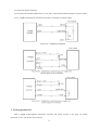
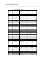
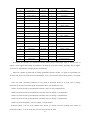
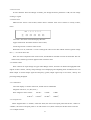
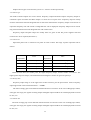
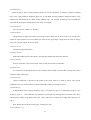
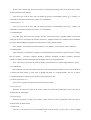
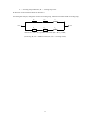
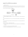
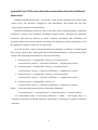
L_Mag Electromagnetic Flowmeter Converter User’s Manual L-Mag(B)Series 7.2011 CONTENTS 1. THE PRODUCT FUNCTION INTRODUCTION............................................................... 1 1.1 BASIC FUNCTION............................................................................................................1 1.2 ESPECIAL FUNCTION...................................................................................................... 1 1.3 NORMAL OPERATING CONDITIONS........................................................................................2 1.4 TYPE OF CONNECTING WITH SENSORS...................................................................................2 1.5 PLOT OF INSTALLING MEASURE............................................................................................2 2. BASIC CIRCUIT OF CONVERTER.....................................................................................4 3. INDEX OF TECHNICAL PERFORMANCE....................................................................... 5 3.1 STANDARD OF IMPLEMENT................................................................................................... 5 3.2 BASIC PARAMETERS AND PERFORMANCE INDEX........................................................... 5 4. OPERATION CONVERTER..................................................................................................8 4.1 KEY AND DISPLAY................................................................................................................ 8 4.1.1 L_MAG_3KEYS AND DISPLAY...........................................................................................8 4.1.2L_MAG_4KEYS AND DISPLAY............................................................................................9 4.2SECTION PICTURE OF CONVERSION...................................................................................... 10 4.3CONNECTIONS OF SENSOR................................................................................................... 11 4.4 CHARACTERISTIC AND CONNECTION OF CABLE......................................................... 14 4.5 DIGITAL OUTPUT AND CALCULATE..................................................................................... 17 4.6 SIMULATION SIGNAL OUTPUT AND CALCULATE.........................................................20 5. SETTING PARAMETERS................................................................................................... 23 5.1 L_MAGB_3 KEY PARAMETERS AND SETTING.....................................................................23 5.2 L_MAGB_4 KEY PARAMETERS AND SETTING.....................................................................27 5.3 DETAILS PARAMETERS....................................................................................................... 32 6. INFRARED TELECONTROL FUNCTION KEYS.......................................................... 38 7. ALARM INFORMATION....................................................................................................39 8. TROUBLESHOOTING........................................................................................................ 39 8.1 NO DISPLAY:....................................................................................................................... 39 8.2 EXCITING ALARM............................................................................................................... 39 8.3 EMPTY PIPE ALARM............................................................................................................ 40 8.4 MEASURE FLOW DISALLOW................................................................................................40 9. L_MAGB ENCASEMENT AND RESERVE......................................................................41 9.1 L_MAGB ENCASEMENT......................................................................................................41 9.2 SHIPPING AND STORAGE..................................................................................................... 41 APPENDIX ONE: SELECTION OF EXCITING FREQUENCY(RE.)......................... 42 APPENDIX TWO ON/OFF SWITCH DIAGRAM.................................................................44 APPENDIX THREE:HART FUNCTION EXPLAINATION............................................... 45 APPENDIXFOUR:211BSERIESWITHNONLINEARAMENDMENTFUNCTIONADDITIONAL INSTRUCTION..........................................................................................................................46 APPENDIXFIVE:THE FUNCTION OF PROTECTING THE CHARACTERISTIC FLOW FACTOR 48 APPENDIX SIX LIGHTNING PROTECTION NOTES....................................................... 49 L_Mag (B) Electrometric Flowmeter Converter Instruction Manual 1. The product function introduction 1.1 Basic function ■ Low-frequency square-wave exciting,exciting frequency:1/16 power frequency、1/20power frequency、 1/25 power frequency; ■ High-frequency square-wave exciting,exciting frequency: 1/2 power frequency(for grouting liquid measure); ■ Exciting current can be selected for 125mA、187.5mA、250mA、500 mA; ■ No need to add empty pipeline measurement, and can measure continuously, alarm by fixed value; ■ Current speed range:0.1 --- 15m/s,current speed resolution:0.5mm/s; ■ AC high-frequency switching power,range of voltage:85VAC --- 250VAC; ■ DC 24V switching power,range of voltage:20VDC --- 36VDC; ■ Network function:MODBUS、GPRS、PROFIBUS 、HARTcommunication interface(choose); ■ Chinese or English displaying mode, (other languages can be set); ■ Three integrator gross inside, respective register: Forward gross, reverse gross and minus value gross. 1.2 Especial function ■ Recording time when power turn-off, to record power broken time of instrument system automatically and recruit to count the missing flux; ■ Recording function of hour gross, to record the flux gross by hour, fit for timed measure; ■ Infrared handing telecontrol keyboard,all the functions of far-untouched controlling converter. 1.3 Normal operating conditions Ambient Temperature Ranges:fission –10~+60℃; Relative Humidity:5%~90%; Power Supply: 85~250V,45~63Hz ( single-phase AC). Dissipation Power: <20W( After connecting sensor). 1.4 Type of connecting with sensors The integrated circinal shells: circinal shells, shells connect with the flange directly, explosion-proof; The integrated squared shells: squared shells, shells connect with the flange directly; 1 The split squared shells: squared shells (hang on the wall), Signal converters connect with cable of sensor; 1.5 Plot of installing measure Fig.1 Exterior size of the integrated circinal shells Fig.2 Exterior size of the integrated squared shells 2 Fig.3 Exterior size of the split squared shells 2. Basic circuit of converter 32 bit CPU preampli fier 85~260V 45~63Hz A/D ROM exciting circuit EEROM Switching Power Supply 4-20mA or 0-10mA 1-5000Hz Frequency or Pulse Output Current Output LCD Display Keyboard Pulse Output Status Control OC Gate Status Output Communication Interface RS485 .etc Fig.2. 1 Structure Of Converter’s Circuit The converter can supply exciting current to the coil in the sensor of electronetic flowmeters,the head amplifier amplifies the electromotive force from the sensor and converts it into standard signals of current or frequency so that the signals can be used for displaying, controlling and processing. See structure of 3 converter circuit shown in Fig.2.1。 3. Index of technical performance 3.1 Standard of implement The design, production and instrument of L_MagB Electromagnetic Flowmeter Converter implement 《JJG-1033-2007 Electromagnetic Flowmeters》。 3.2 Basic parameters and performance index 3.2.1 Pipe’s inside diameter of relative sensor (mm): 3、6、10、15、20、25、32、40、50、65、80、100、125、150、200、250、300、350、400、450、 500、600、700、800、900、1000、1200、1400、1600、1800、2000、2200、2400、2500、2600、2800、 3000; 3.2.2 Request of relative sensor Sensitivity of sensor signal: under 1m/s, output 150µV ~200µV; For L_MagB electromagnetic flowmeter signal converters, there are two currents of 125mA in exciting loop, which make up of 250mA, and every 125mA is controlled by one 10Ω exact resistance. So user can choose different exciting current by changing the number of exact resistance. The current will be 250mA when the signal converters leave factory, as such, if there are three 20Ω exact resistance or one 20Ω and one 10Ω exact resistance, the current will be 187.5 mA; if two 20Ω, 125mA. Resistance of sensor exciting coil: 500mA exciting current:20 ~ 30Ω; 250mA exciting current:50 ~ 60Ω; 187mA exciting current:60 ~ 80Ω; 125mA exciting current:100 ~ 120Ω; 4 3.2.3 Measure precision for assembly Table 3.1 VS:Setting measurement range (m/s) Diameter(mm) 3 ~ 20 25 ~600 700~3000 Range(m/s) Accuracy ≤0.3 ±0.25%FS 0.3~1 ±1.0R 1~15 ±0.5%R 0.1~0.3 ±0.25%FS 0.3~1 ±0.5%R 1~15 ±0.3%R ≤0.3 ±0.25%FS 0.3~1 ±1.0%R 1~15 ±0.5%R %FS:for relative ranges; %R:for relative value of measurement 3.2.4 Simulated current output Load resistor: 0~1.5kΩ (0~10mA); 0~750Ω (4~20mA). Basic Errors: 0.1%±10μA. 3.2.5 Digital frequency output Frequency output range: 1~5000Hz; Output electric isolate: Photoelectric isolate. Isolate voltage: > 1000VDC; Frequency output drive: output by field-effect transistors, the highest subjected voltage is 36VDC , maximum of output current is 250 mA. 3.2.6 Digital pulse output Pulse output range: 0 ~100 pulse/s。(When higher than upper limit, pulse will lose); Pulse output value: 0.001~1.000 m3 / cp 0.001~1.000 Ltr / cp Pulse output width: 50ms, Pulse output isolate: photo electricity isolate. Isolate voltage: > 1000VDC; Pulse output drive: output by field-effect transistors, the highest subjected voltage is 36VDC,maximum 5 of output current is 250 mA. 3.2.7 Alarm output Alarm output junction:ALMH--- upper limit; ALML--- lower limit; Output isolate: photo electricity isolate. Isolate voltage: > 1000VDC; Alarm output drive: output by Darlington pipe, the highest subjected voltage is 36VDC,maximum of output current is 250 mA. 3.2.8 Digital communication port and protocol MODBUS interface: format of RTU. HART interface: designed by standard of HART , if you choose our hand held unit , you can display the measure value on line,and setting the parameters. 3.2.9 Electric isolate Insulated voltage between simulated input and simulated output should be higher than 500V; Insulated voltage between simulated input and alarm power supply should be higher than 500V; Insulated voltage between simulated input and AC power supply should be higher than 500V; Insulated voltage between simulated output and AC power supply should be higher than 500V; Insulated voltage between simulated output and earth should be higher than 500V; Insulated voltage between pulse output and AC power supply should be higher than 500V; Insulated voltage between pulse output and earth should be higher than 500V; Insulated voltage between alarm output and AC power supply should be higher than 500V; Insulated voltage between alarm output and earth should be higher than 500V; 4. Operation converter 4.1 Key and display 4.1.1 L_Mag_3Keys and display 4.1.1.1Squared define keys and LCD screen display 6 Fig. 4.1 (a) Keys on squared panel and large LCD display: 4.1.1.2Rotundity define keys and LCD screen display Fig. 4.1 (b) Keys on circinal panel and big LCD display Note: Press enter key, the instrument enter into the setting parameters of select function. Movie the cursor under the enter key. Press it. and then input password when password status“00000”can be seen. Movie the cursor under the enter key again. Press it. And then input settings into selected item of operating manus .Please push “▼”key down for several seconds for returning to running status. 4.1.2L_Mag_4Keys and display 4.1.2.1Squared define keys and LCD screen display 7 Fig. 4.1 (c) Keys on squared panel and large LCD display: 4.1.2.2Rotundity define keys and LCD screen display Fig. 4.1(d) Keys on circinal panel and big LCD display Note: When measuring, pushing down “Compound Key + Enter” will appear password of changing state, base on distinction of secrecy, and change the password as we provide. Then pushing “Compound Key + Enter” again, and you can inter the state of setting parameter. If want to return to the running state, push “Enter” for several seconds. 4.2Section picture of conversion 4.2.1 L_Mag_3 Keys Series 8 Fig.4.2 (a) L_Mag211B-3 Key Fig.4.2(b) L_Mag411B-3 Key 4.2.2L_Mag_4 Keys Series Fig.4.2 (c) L_Mag211B-4 Key Fig.4.2 (d) L_Mag411B-4 Key 4.3Connections of sensor 4.3.1 Connectors and labels for the squared 9 DS2 MTSR SIG1 SGND SIG2 DS1 IOUT TRX+ VDIN TRX- ICOM EXT- EXT+ TCOM ALMH ACOM POUT ALML PCOM PO W ER ACOM L PE N RS485 PE Fig.4.3 (a) Connectors for 211B Labels of connectors in squared model 4.3.2 Signal lines and labels in squared model ф2 Terminal Cold-Welded ф2 Terminal Cold-Welded Metal Screen ф10 Heat Shrink Tube Red 32 Conductor Shielded Cable Metal Screen ф10 Heat Shrink Tube Red 32 Conductor Shielded Cable Green 32 Conductor Shielded Cable Green 32 Conductor Shielded Cable Cable for Flow Signals:RVVP2ⅹ32 /0.2 Fig.4.3 (b) Connection and labels of signal lines in squad model 10 4.3.3 Links and labels of connectors in Circinal Model + COM I+ COM P+ AH AL + + + + + + T+ G + + + + + + + FUSE + L2 L1 + + T- Fig.4.3(c) Connectors in circinal model Symbols and Description of Connectors in Circinal Pane I+: Output Current for Flow Measurement COM: Output Current (Ground) for Flow Measurement P+: Frequency(Pulse) Output for Bi-directional Flow COM: Frequency (Pulse) Output (Ground) AL: Alarm Output for Low Limit AH: Alarm Output for Upper Limit COM: Alarm Output (Ground) FUSE: Fuse for Power Supply T+: +Communication Input Signal(RS485-A) T-: -Communication Input Signal(RS485-B) G RS232 Communication Ground L1: 220V(24V)Power Supply L2: 220V(24V)Power Supply 4.3.4 Labels and connection of signal lines in circinal model 11 White Cable Red 12 Conductor Shielded Cable) Black 12 Conductor Shielded Cable Red 10 Conductor Shielded Cable White 13 Conductor Shielded Cable Shield Screen Gray Shielded Cable Fig.4.3 (d) Labels and connection of signal lines in circinal model Signal lines labels in circinal model: White twisted-pair cable (for exciting current): 12 Conductors (Red) 12 Conductors (Black) Gray shielded twisted-pair cable: 10 Conductors (Red) connected to “Signals 1” 13 Conductors (White) connected to “Signals 2” Shielded Conductor connected to “Signal Ground” 4.4 Characteristic and connection of cable 4.4.1 Flux signal line When separated models of converters are assembled with sensors for measuring flow of fluid which conductivity is larger than 50μS/cm, PVVP 2*0.2 mm2 model cable ( metal shielded signal cable covered with PVC) can be used as communication cable for flow signals. The length of signal cable should be less than 100 m. Signal cables have to be connected to sensors that were assembled by producers. Connections of signal cables are shown in Fig.4.3(b) for squire-shaped models and Fig.4.3(d) for circle-shaped models, respectively. The converter can output equivalent level of shielded exciting signal voltage so that interference to flow measurement signals can reduced by means of lowering the distributed capacitance of communication cable. When measured conductivity is less than 50μS/cm or signals are transferred in remote distances, double-conductor and double-shielded signal cable at equivalent level of voltage can be used. For example, special STT3200 cable or BTS model signal cable (triple-shielded) can be used for signal communication. 4.4.2 Exciting current cable Two conductor and insulating rubber- covered cables can be used as exciting current cables. Suggested model is RVVP2*0.3mm2 . Length of exciting current cable should be equal to that of signal cable. When the model STT3200 cables are used for exciting current and signals, two cables can be put together as one cable. 12 4.4.3 Output and power line All cables for signals transferring and power supply have to be prepared by users. However, it should be careful to choose the cables that meet the upper limit load of consuming current. Note: When DIP switch next to terminal is set to ON places, the converter from its inside can provide +28Vpower supply and up-pull 10kΩ resistance to output Frequencies (PUL) to isolated OC gate, Alarm Output (ALMH.ALML), and Status Control(INSW).Therefore, when converter has frequency output and works with sensor together, DIP switch can be set as ON getting frequency signals from POUT and PCOM terminals. Pulse current output, alarm current output and external power supply can be seen in Fig.4.4(a). When inductive load is connected to converter, diode should be used as in Fig.4.4(b). Fig.4.4 (a) Output current circuit Fig.4.4 (b) Connection of electro-magnet counter 13 Fig.4.4 (c) Connection of electronic counter Fig.4.4 (d) Connection of alarm output inside outside Pout ALMH ALML PCOM ALCOM Fig.4.4(e)Connection of OC gate 4.4.4 Grounding Contact area of copper Connector PE on Converter Cabinet for grounding should be larger than 1.6mm2.Contact resistance should be less than 10Ω. 14 4.5 Digital output and calculate Digital output means frequency output and pulse output, and both of them use the same output point, so user can choose only one type of them but not both. 4.5.1 Frequency output Frequency output range is 0~5000HZ, and corresponding the percent of flux. F= Measure value frequency range Full scale value The up limit of frequency output can be adjusted. It can be chosen from 0 ~ 5000HZ, and also can be chosen low frequency: such as 0 ~ 1000HZ or 0 ~ 5000HZ. Frequency output mode general can be used in control application, because it responses the percent flux. Users can choose pulse output when the equipment is applied to count. 4.5.2 Pulse output mode: Pulse output mainly applies in count mode. A pulse output delegates a unit flux, such as 1L or 1M3 etc. Pulse output unit divide into0.001L, 0.01L, 0.1L, 1L, 0.001M3, 0.01M3, 0.1M3, 1 M3 .When users choose the pulse unit, they should notice the match of the flux range of flowmeter and pulse unit. For volume flux, count formula as follows: QL=0.0007854×D2×V (L/S) Or QM=0.0007854×D2×V×10-3 (M3/S) Note: D-nozzle (mm) V-velocity of flow (m/s) The oversize flux and too small pulse unit will be made the pulse output over the up limit. Generally, pulse output should be controlled below 3000P/S. However, the too small flux and too large pulse unit will be made the instrument exports a pulse long time. Otherwise, pulse output is different from frequency output. When pulse output cumulates a pulse unit, it exports a pulse. Therefore, pulse output is not equality. Generally, measure pulse output should chooseto count instrument, but not frequent instrument. 4.5.3 The connection of digital output Digital output has tow connected points: digital output connected point, digital ground point, and symbol as follows: POUT ----- digital output point; PCOM ----- digital ground point; 15 POUT is collector plough output, user may refer to next circuit to connect. 4.5.4 The connection of digital voltage output Pout + - E Voltage input Com Pcom Inside User equipment Pin R Fig.4.5(a) The connection of digital voltage output 4.5.5 Digital output connect photoelectricity coupling (PLC etc.) Pout R E inside + - User equipment Pcom Fig.4.5(b) Digital output connect photoelectricity coupling Commonly user’s photoelectricity coupling current is about 10mA, so about E/R=10mA, E=5~24V. 4.5.6 Digital output connect relay J Pout + - E inside D Pcom Fig.4.5(c) Digital output connect relay Commonly relay needs E as 12V or 24V. D is extend diode, now most middle relays has this diode inside. If not have, user can connect one outside. Table of digital output parameter: POUT Parameter Volatge Test condition IC=100 mA Mini Typical Max Unit 3 24 36 V 16 Current Frequency Vol≤1.4V IC=100mA Vcc=24V 0 300 350 mA 0 5000 7500 HZ High voltage IC=100mA Vcc Vcc Vcc V Low voltage IC=100mA 0.9 1.0 1.4 V 4.6 Simulation signal output and calculate 4.6.1 Simulation signal output There are two signal system: 0~10mA and 4~20mA, user can select from parameter setting. Simulation signal output inner is 24V under0~20mA, it can drive 750Ω resistance. The percent flux of simulation signal output: I0= Measure value the scale of current + the zero point of current Full scale value The current zero is 0 when 0~10mA, and the current zero is 4mA when 4~20mA. It can be advanced simulation signal output distinguish. User can select the range of measure. The manufacture’s parameter have been adjusted, it can’t need adjust. If have abnormity, it can consult 4.6.2. 4.6.2 Simulation Signal Output Adjust (1)The Converter adjust preparative When the converter is running 15 minutes, the inner of converter becomes stabilization. Preparative 0.1% amperemeter or 250Ω、 0.1% voltage instrument. 1.000 IOUT Converter DC20V ICOM (2)Current zero correct When the converter getting into parameter setting, selecting to “Analog Zero” and enter to it. The standard of signal fountain getting to “0”.Adjust parameter make amperemeter is 4mA(±0.004mA). (3)The full scale current correct To select “Anlg Range” to enter.Adjust the converter parameter make amperemeter is 20mA(±0.004mA) Adjust the current zero and the full range, the current function of the converter reached exactness.The line degree of current output of conversion should be controlled within the scope of 0.1% 17 (4) Current line degree checking You can place the standard signal source in 75%、50%、25%,and check the line degree of current output. 4.6.3 L_magB electromagnetic flowmeter converter’s connection of current output: 5. Setting parameters After L_MagB electromagnetic flowmeter converter and sensor connect to the pipe (no matter demarcate or use), may do the next work first: 18 Connect the pipe fore-and-aft the sensors tighten. Make sure the sensor connects the earth. Make sure the liquid stillness when regulating zero of the instrument. Make sure the oxidation velum of sensor makes steadily (electrode and liquid contact continuously about 48 hours). 5.1 L_MagB_3 key parameters and setting When electrify, the instrument comes into measure way automatically, and under this way it can do all the functions and display data. Under the parameter setting way, user can set the parameter by the three keys. 5.1.1 Keys function a) Keys’ function in self- testing way “Down” key: Selecting displayed data on lower line in turn; “Enter” key: Press it to come into the interface of select function. “Shift” key: Press it to move the cursor. Under the measure, adjust of the LCD contract: push “Down” Key and “Shift” key or “Down” Key and “Enter” key. b) Function keys for parameters setting “Down” key: Subtract 1 from the number at cursor area; “Up” key: Plus 1 to the number at cursor area; Push “Shift” key to move the cursor to “Up” key, push “Up” key to the submenu; Push “Shift” key to move the cursor to “Down” key, push “Down” key return to the father menu. 5.1.2 Function keys for setting parameters To set or correct working parameters, the converter should be running in parameters setting way instead of measuring status. In measuring status, push “Enter” key getting to the select of parameter and transfer password (0000), and then correct the password with one of the new passwords that are provided by manufacturer. Finally, push the “Enter” key to work in Parameters Setting Way. Basis to the level of secrecy, amend according to the passwords we give. Then push “Enter” key to the interface needed. There are 6 Passwords in design and among them 4 for deferent operators in secret and 2 are fixed passwords for system operation. 5.1.3. Functions select menu 19 Push “Enter” key to the functions select menu, push “Enter” key to select, there are three functions: Code Functions 1 Parameters Set 2 Clr Total Rec 3 Fact Modif Rec Notes Select this function; It can be entering the picture of parameter. Select this function , It can be gross reset operation. Select this function, It can be check the factor ‘s modif Record 5.1.3.1 Parameters setting Press “Enter” key, it displays “Parameters Set” function. Input password. Press “Shift” key, Movie cursor on the “Enter” key, Press it getting to Parameters Setting status. 5.1.3.2 Clr Total Rec To push “Enter” key getting to the select of parameter, then push “Up” key to “Clr Total Rec”, input the passwords. When the passwords becomes “00000”, this function is done, the gross is 0 in the instrument. 5.1.4 Setting Parameters in Menu There are 54 parameters of L_MagB, user can set every parameter. The List of Parameters is shown below: Setting Parameters in Menu Code Parameter words Setting Way Grades Range 1 Language Select 2 English 2 Comm Addres Set count 2 0~99 3 Baud Rate Select 2 300~38400 4 Snsr Size Select 2 3~3000 5 Flow Unit Select 2 L/h、L/m、L/s、m3/h、 m3/m、m3/s 6 Flow Range Set count 2 0~99999 7 Flow Rspns Select 2 1~50 8 Flow Direct Select 2 Plus/ Reverse 9 Flow Zero Set count 2 0~±9999 10 Flow Cutoff Set count 2 0~599.99% 11 Cutoff Ena Select 2 Enable/Disable 12 Total Unit Select 2 13 SegmaN Ena Select 2 Enable/Disable 14 Analog Type Select 2 0~10mA /4~20mA 15 Pulse Type Select 2 Freque / Pulse 16 Pulse Fact Select 2 0.001m3~1m3 0.001L~1L、 17 Freque Max Select 2 1~ 5999 HZ 20 0.001m3~1m3 、 0.001L~1L、 、 18 Mtsnsr Ena Select 2 Enable/Disable 19 Mtsnsr Trip Set count 2 59999 % 20 Alm Hi Ena Select 2 Enable/Disable 21 Alm Hi Val Set count 2 000.0~ 599.99 % 22 Alm Lo Ena Select 2 Enable/Disable 23 Alm Lo Val Set count 2 000.0~599.99 % 24 Sys Alm Ena Select 2 Enable/Disable 25 Clr Sum Key Set count 3 0~99999 26 Snsr Code1 User set 4 Finished Y M 27 Snsr Code2 User set 4 Product number 28 Field Type Select 4 Type1,2,3 29 Sensor Fact Set count 4 0.0000~5.9999 30 Line CRC Ena Select 2 Enable/Disable 31 Lineary CRC1 User set 4 Set Velocity 32 Lineary Fact 1 User set 4 0.0000~1.9999 33 Lineary CRC2 User set 4 Set Velocity 34 Lineary Fact 2 User set 4 0.0000~1.9999 35 Lineary CRC3 User set 4 Set Velocity 36 Lineary Fact 3 User set 4 0.0000~1.9999 37 Lineary CRC4 User set 4 Set Velocity 38 Lineary Fact4 User set 4 0.0000~1.9999 39 FwdTotal Lo Correctable 5 00000~99999 40 FwdTotal Hi Correctable 5 00000~9999 41 RevTotal Lo Correctable 5 00000~99999 42 RevTotal Hi Correctable 5 00000~9999 43 PlsntLmtEna Select 3 Enable/Disable 44 PlsntLmtVal Select 3 0.010~0.800m/s 45 Plsnt Delay Select 3 400~2500ms 46 Pass Word 1 User correct 5 00000~99999 47 Pass Word 2 User correct 5 00000~99999 48 Pass Word 3 User correct 5 00000~99999 49 Pass Word 4 User correct 5 00000~99999 50 Analog Zero Set count 5 0.0000~1.9999 51 Anlg Range Set count 5 0.0000~3.9999 52 Meter Fact Set count 5 0.0000~5.9999 53 MeterCode 1 Factory set 6 Finished Y /M 54 MeterCode 2 Factory set 6 Product Serial No Parameters of converters can decide the running status, process and output ways as well as state of output. Correct option and setting of parameters can keep the converters running optimally and get higher accuracies of output bother in display and in measurement. 21 There are 6 grades of passwords for setting parameters function. Grades 1 to grade 5 of passwords are for users and grade 6 of password is for manufacturer. Users can reset their passwords of grades 1~4 in grade 5. Users can check converters parameters in any grade of password. However, if users want to change parameters pf converters, deferent grade of parameters have to be used by the users. Grade 1 of password (set by manufacturer as 00521): users can only read parameter. Grade 2 of password (set by manufacturer as 03210): users can change 1~24 parameters. Grade 3 of password (set by manufacturer as 06108): users can change 1~25parameters. Grade 4 of password (set by manufacturer as 07206): users can change 1~38parameters. Grade 5 of password (Fixed): users can change 1~52 parameters. Password Grade 5 can be set by skilled users. Grade 4 is mainly used for resetting total volume in password. Grades 1~3 can be set by any one who can be chosen by users. 5.2 L_MagB_4 key parameters and setting When electrify, the instrument comes into measure way automatically, and under this way it can do all the functions and display data. Under the parameter setting way, user can set the parameter by the four keys. 5.2.1 Keys function a) Keys’ function in self- testing way “Down” key: Selecting displayed data on lower line in turn; “Up” key: Selecting displayed data on higher line in turn; “Compound” key + “Enter” key: Come into parameter setting “Enter” key: Press it to come into the picture of select function. Under the measure, adjust of the LCD contract is used “Compound” key + “Up” key or key + “Down” key for several seconds; “Compound” b) Function keys for parameters setting “Down” key: Subtract 1 from the number at cursor area; “Up” key: Plus 1 to the number at cursor area; “Compound” key + “Down” key: Cursor turns left; “Compound” key + “Up” key: Cursor turns right; “Enter” key: In/Out submenu; “Enter” key: Press for two seconds under any state and will return to automate measure way. Note: (1)When use “Compound” key, you should press “Compound” key and “Up” or “Down” both; 22 (2) It will return to the measure way automatically after 3 minutes when under the parameter setting way; (3) Direct select of zero correction about the flow, you can move the cursor to the left + or - , and use “Down” or “Up” to switch; 5.2.2 Function keys for setting parameters To set or correct working parameters, the converter should be running in parameters setting way instead of measuring status. In measuring status, push “Compound”+“Enter” keys getting to the select of parameter and transfer password (0000), and then correct the password with one of the new passwords that are provided by manufacturer. Finally, push the “Compound”+“Enter” keys to work in Parameters Setting Way. There are 6 Passwords in design and among them 4 for deferent operators in secret and 2 are fixed passwords for system operation. 5.2.3. Functions select menu Push “Compound”+“Enter” keys to the functions select menu, push “Up” or “Down” keys to select, there are three functions: Code Functions 1 Parameters Set 2 Clr Total Rec 3 Fact Modif Rec Notes Select this function; It can enter the picture of parameter. Select this function,It can be gross reset operation. Select this function, It can be check the factor ‘s modif Record 5.2.3.1 Parameters Set Press “Compound”+“Enter” key, it displays “Parameters Set” function. Input password. Press “Compound”+“Enter” key, it getting to Parameters Setting status. 5.2.3.2 Clr Total Rec To push “Compound”+“Enter” keys getting to the select of parameter, then push “Up” key to “Clr Total Rec”, input the passwords. When the passwords becomes “00000”, this function is done, the gross is 0 in the instrument. 5.2.3.3 Fact Modif Rec To push “Compound”+“Enter” keys getting to the select of parameter, then push “Up” key to “Fact Modif Rec”(Detail consult the AppendixFive) 23 5.2.4 Setting Parameters in Menu There are 54 parameters of L_MagB, user can set every parameter. The List of Parameters is shown below: Setting Parameters in Menu Code Parameter words Setting Way Grades Range 1 Language Select 2 English 2 Comm Addres Set count 2 0~99 3 Baud Rate Select 2 300~38400 4 Snsr Size Select 2 3~3000 5 Flow Unit Select 2 L/h、L/m、L/s、m3/h、 m3/m、m3/s 6 Flow Range Set count 2 0~99999 7 Flow Rspns Select 2 1~50 8 Flow Direct Select 2 Plus/ Reverse 9 Flow Zero Set count 2 0~±9999 10 Flow Cutoff Set count 2 0~599.99% 11 Cutoff Ena Select 2 Enable/Disable 0.001m3~1m3 、 0.001L~1L、 12 Total Unit Select 2 13 SegmaN Ena Select 2 Enable/Disable 14 Analog Type Select 2 0~10mA /4~20mA 15 Pulse Type Select 2 Freque / Pulse 16 Pulse Fact Select 2 0.001m3~1m3 0.001L~1L、 17 Freque Max Select 2 1~ 5999 HZ 18 Mtsnsr Ena Select 2 Enable/Disable 19 Mtsnsr Trip Set count 2 59999 % 20 Alm Hi Ena Select 2 Enable/Disable 21 Alm Hi Val Set count 2 000.0~ 599.99 % 22 Alm Lo Ena Select 2 Enable/Disable 23 Alm Lo Val Set count 2 000.0~599.99 % 24 Sys Alm Ena Select 2 Enable/Disable 25 Clr Sum Key Set count 3 0~99999 26 Snsr Code1 User set 4 Finished Y M 27 Snsr Code2 User set 4 Product number 28 Field Type Select 4 Type1,2,3 29 Sensor Fact Set count 4 0.0000~5.9999 30 Line CRC Ena Select 2 Enable/Disable 31 Lineary CRC1 User set 4 Set Velocity 32 Lineary Fact 1 User set 4 0.0000~1.9999 33 Lineary CRC2 User set 4 Set Velocity 24 、 34 Lineary Fact 2 User set 4 0.0000~1.9999 35 Lineary CRC3 User set 4 Set Velocity 36 Lineary Fact 3 User set 4 0.0000~1.9999 37 Lineary CRC4 User set 4 Set Velocity 38 Lineary Fact4 User set 4 0.0000~1.9999 39 FwdTotal Lo Correctable 5 00000~99999 40 FwdTotal Hi Correctable 5 00000~9999 41 RevTotal Lo Correctable 5 00000~99999 42 RevTotal Hi Correctable 5 00000~9999 43 PlsntLmtEna Select 3 Enable/Disable 44 PlsntLmtVal Select 3 0.010~0.800m/s 45 Plsnt Delay Select 3 400~2500ms 46 Pass Word 1 User correct 5 00000~99999 47 Pass Word 2 User correct 5 00000~99999 48 Pass Word 3 User correct 5 00000~99999 49 Pass Word 4 User correct 5 00000~99999 50 Analog Zero Set count 5 0.0000~1.9999 51 Anlg Range Set count 5 0.0000~3.9999 52 Meter Fact Set count 5 0.0000~5.9999 53 MeterCode 1 Factory set 6 Finished Y /M 54 MeterCode 2 Factory set 6 Product Serial No Parameters of converters can decide the running status, process and output ways as well as state of output. Correct option and setting of parameters can keep the converters running optimally and get higher accuracies of output bother in display and in measurement. There are 6 grades of passwords for setting parameters function. Grades 1 to grade 5 of passwords are for users and grade 6 of password is for manufacturer. Users can reset their passwords of grades 1~4 in grade 5. Users can check converters parameters in any grade of password. However, if users want to change parameters pf converters, deferent grade of parameters have to be used by the users. Grade 1 of password (set by manufacturer as 00521): users can only read parameter. Grade 2 of password (set by manufacturer as 03210): users can change 1~24 parameters. Grade 3 of password (set by manufacturer as 06108): users can change 1~25parameters. Grade 4 of password (set by manufacturer as 07206): users can change 1~38parameters. Grade 5 of password (Fixed): users can change 1~52 parameters. Password Grade 5 can be set by skilled users. Grade 4 is mainly used for resetting total volume in password. Grades 1~3 can be set by any one who can be chosen by users. 25 5.3 Details Parameters 5.3.1 Language There are 2 languages for L_MagB converter operation. They can be set by users according to the users needs. 5.3.2 Comm Addres It means this instrument’s address when communicates with many, and has 01~99, holding the 0. 5. 3.3 Baud Rate 300, 1200, 2400, 4800, 9600, 38400, baud rate. 5.3.4 Snsr Size L_MagB converters can be equipped with some deferent sensors that have deferent diameter of measuring pipes. The pipes in deferent diameters from 3mm to 3000mm can be chosen in relative table. 5.3.5 Flow unit The flow unit can choose form the parameters (L/s、L/m、L/h、m3/s、m3/m、m3/h),and the user can choose the proper unit according to the technological requirement and using habit. 5.2.6 Flow Range Flow range means upper limit value, and lower limit value is set “0” automatically. So, it makes the range, and makes the relation of percent display, frequency output and current output with flow: percent display = ( flow measure / measure range) * frequency output = ( flow measure / measure range) 100 %; * frequency full; current output = ( flow measure / measure range) * current full + base point; pulse output will not affect. 5.3.7 Flow Rspns It means time of filter measure value. The long one can enhance the stability of flow display and output digital, and fits for gross add up of pulse flow; the short one means fast respond rate, and fits for production control. It is set by select. 26 5.3.8 Flow Direct If users think the direct and design are differ, just change the direct parameter is OK, but not change exciting or signal. 5.3.9 Flow zero Make sure the sensor is full of flow, and the flow is stillness. Flow zero is shown as velocity of flow, mm/s. FS = ○ ○ ○ ○ ○ ± ○ ○ ○ ○ ○ Converter’s zero-flow correction displays like this: Upper small words: FS means measure value of zero; Lower large words: correction value of zero. When FS is not “0”, make FS = 0. Note: if change the value on next line and FS increases, please change the “+, -” to correct FS to zero. Flow zero is the compound value of the sensor, and should be recorded in sensor list and band. The unit will be mm/s, and the sign will be opposite with correction value. 5.3.10 Flow cutoff Flow cutoff is set in percentage of Upper Limit Range of flow, and users can delete all Negligible Small Signals of flow volume, velocity and percentage out of displaying and outputting them. Sometimes user can delete output of current output signal and frequency (pulse) output signal only to have flow, velocity and percentage being displayed. 5.3.11 Total Unit Converter display is counter with 9 bits, and the max is 999999999. Integrator units are L, m3 (liter, stere,). Flow integrator value: 0.001L、 0.001m3、 0.010L、 0.100L、 1.000L 0.010m3、 0.100m3、 1.000m3 ; 5.3.12 SegmaN Ena When “SegmaN Ena” is “enable”, if the flow flows, the sensor will export pulse and current。When it is “disable”, the sensor will export pulse as “0” and current as “0”(4mA or 0mA) for the flow flows reversals. 5.3.13 Output currents 27 Output current types can be chosen by users as 1~10mA or 4~20mA practically. 5.3.14 Pulse Type Two kinds of Pulse Outputs are can be chosen: Frequency Output and Pulse Output. Frequency Output is continuous square waveform and Pulse output is a serial wave of square wave. Frequency output is mainly used for instant flow and total integrated flow in short time measurement. Frequency output can be chosen in equivalent frequency unit and volume of integrated flow can be displayed. Frequency Output can be used in long time measurement for total integrated flow with volume units. Frequency output and pulse output are usually from OC gates so that DC power supplies and load resistors have to be required (See Part 4.5). 5.3.15 Pulse Fact Equivalent pulse Unit is referred to one pulse for value of flow. The range of pulse equivalent can be chosen: Pulse Equivalent Flow Pulse Equivalent Flow 1 0.001L/cp 5 0.001m3/cp 2 0.01L/cp 6 0.01m3/cp 3 0.1L/cp 7 0.1m3/cp 4 1.0L/cp 8 1.0m3/cp Under the same flow, the smaller pulse, the higher frequency output, and the smaller error will be. The highest pulse output is 100cp/s, and mechanism electromagnetic counter can get 25 frequency/s. 5.3.16Freque Max Frequency output range is as the upper limit of flow measure, just the percent flow 100%. Frequency output upper limit can be selected between 1~5000Hz. The state of empty pipe can be detected with the function of converter. In the case of Empty Pipe Alarm, if the pipe was empty, the signals of analog output and digital output would be zero and displayed flow would be zero, too. 5.3.17Mtsnsr Ena The state of empty pipe can be detected with the function of converter. In the case of Empty Pipe Alarm, if the pipe was empty, the signals of analog output and digital output would be zero and displayed flow would be zero, too. 28 5.3.18Mtsnsr Trip When the pipe is full of liquid (whether flowing or not), the parameter of “Mtsnsr” could be modified more easily. The parameter displayed upper line is real MTP, and the parameter displayed bellow is the “Mtsnsr trip” that should be set. When setting “Mtsnsr trip”, you could be according to the real MTP, the value that should be set is usually three to five times of real MTP. 5.3.19 Alm Hi Ena Users can choose “Enable” or “Disable”. 5.3.20 Alm Hi Val The parameter of upper limit alarm is percentage of flow range and can be set in the way of setting one numerical value between 0%~199.9%.When the value of flow percentage is larger than the value of setting value, the converter outputs the alarm signal. 5. 3.21Alm Lo Val The same as upper limit alarm. 5.3.22 Sys Alm Ena Selecting Enable will have the function, and selecting Disable will cancel the function. 5.3.23 Clr Sum Key User use more than 3 byte code to enter ,Then set this password in Clr Total Rec. 5.3.24 Snsr Code It is referred to the produced date of sensor and the serial number of product that can keep the sensors coefficient right and accurate. 5.3.25 Sensor Fact “Sensor Coefficient” is printed on the Label of the sensor when it is made in factory. The “sensor coefficient” has to be set into Sensor Coefficient Parameter when it runs with converter. 5.3.26 Field Type L_MagB affords three exciting frequency types: 1/16 frequency (type 1), 1/20frequency (type 2), 1/25 frequency (type 3)。 The small-bore one should use 1/16 frequency, and large-bore one should use 1/20 or 1/25 frequency. When using, please select type 1 first, if the zero of velocity is too high, select the type 2 or type 3. Note: Demarcate on which exciting type, working on it only. 5.3.27 FwdTotal Lo、hi 29 Positive total volume high byte and low byte can change forthcoming and reverse total value, and be used to maintenance and instead. User use 5 byte code to enter, and can modify the positive accumulating volume (∑+). Usually, it is unsuitable to exceed the maximum the counter set(999999999). 5.3.28 RevTotal Lo、hi User use 5 byte code to enter, and can modify the negative accumulating volume (∑-). Usually, it is unsuitable to exceed the minimum the counter set(999999999). 5.3.29 PlsntLmtEn For paper pulp, slurry and other serosity, the flow measure will have "cuspidal disturb", because the solid grain friction or concussion the measure electrode. L_MagB converters use variation restrain arithmetic to conquer the disturbing by designing three parameters to select disturb character. Set it "enable", start variation restrain arithmetic; set it "disable", close variation restrain arithmetic. 5.3.30PlsntLmtVl This coefficient can disturb the variation of cuspidal disturb, and calculate as percent of flow velocity, thus ten grades: 0.010m/s, 0.020m/s, 0030m/s, 0.050m/s, 0.080m/s, 0.100m/s, 0.200m/s, 0.300m/s, 0.500m/s, 0.800m/s, and the smaller percent, the higher delicacy of cuspidal restrain. Note: when using it, must test for select by the fact, and sometimes it is not the higher delicacy is good. 5.3.31 PlsntDelay This coefficient can select the width of time of restrain cuspidal disturb and the unit is ms. If the duration is shorter than flow change in some time, L_MagB will think it is cuspidal disturb, and if it is longer, L_MagB will think it is natural. It also needs to select parameter in fact. 5.3.32User’s password 1~4 Users can use 5 grades of passwords to correct these passwords. 5.3.33 Analog Zero When the converters are made in the factory, output current has been calibrated to zero scale, that is, accurate 0mA or 4mA output. 5.3.34 Anlg Range When the converters is made in the factory, output current have been calibrated to full scale, that is, accurate 10mA or 20mA output. 5.3.35Meter Fact This fact is the special one of sensor-made-factory and the factory use this fact to unite L_MagB 30 electromagnetic flowmeters converters to make sure all the instruments can interchange by 0.1%. 5.3.36 MeterCode 1 and 2 Converter code records the date of manufacturing and serial number of converter. 6. Infrared telecontrol function keys The operation of the infrared-hand-remote control keyboard is the same with the operation of the instrument. When use it, please keep the infrared transmitter of the infrared-hand-remote control keyboard and the receiver of the instrument parallel, with the distance of about one meter. Concrete operation referring to the figure: Fig6.1: The communication figure of the infrared-hand-remote control keyboard and the instrument 7. Alarm information PCB of electromagnetic flowmeters converters uses SMT, so for user, it is unable to service, and cannot open the shell of converter. L_Mag-B-3 key series Intelligent converters have self-diagnose function. Without trouble of power and hardware circuit, the normal trouble can be alarmed correctly. This information displays on the left of LCD. The trouble is like this: FQH ---- Flow high limit alarm; FGP ---- Flow empty pipe alarm; FQL ---- Flow low limit alarm; SYS ---- System exciting alarm. L_Mag-B-4series Intelligent converters have self-diagnose function. Without trouble of power and hardware circuit, the normal trouble can be alarmed correctly. This information displays LCD. The trouble is like this: FQH ---- Flow high limit alarm; FGP ---- Flow empty pipe alarm; FQL ---- Flow low limit alarm; SYS ---- System exciting alarm. UPPER ALARM ---- Flow high limit alarm; LOWER ALARM ---- Flow empty pipe alarm; LIQUID ALARM ---- Flow empty pipe alarm; 31 on the left of SYSTEM ALARM ---- System exciting alarm. 8. Troubleshooting 8.1 No display: a) Check the power supply connection; b) Check the power fuse to see for OK; c) Check the contrast of LCD and regulate it to working state; 8.2 Exciting alarm a) Check if the exciting cables EX1 and EX2 did not connected; b) Check if the total resistance of sensor’s exciting coil resistances less than 150Ω; c) If a) and b) are OK, the converter is failed. 8.3 Empty pipe alarm * If measured fluid full of testing pipe of sensor; * When shorting circuit three connectors SIG 1, SIG 2, SGND of converter, and no “Empty Alarm” displayed then the converter works OK. In this case, it is possible that conductivity of measured fluid may be small or empty threshold of empty pipe and range of empty pipe are set wrongly. * Check if the signal cable is OK; * Check if the electro-poles are OK or not. Let the flow is zero, then the displayed conductivity should be less than 100%. Resistances of SIG1 to SGND and SIG2 to SGND are all less than 50kΩ (conductivity of water) during measurement operation. (It is better to test the resistances by means of multimeter with pointer to see the charging process well.) * The DC voltage should be less than 1V between DS1 and DS2 testing the voltage by means of multimeter. If DC voltage is larger than 1V, the electro poles of sensor were polluted that have to be cleaned. 8.4 Measure flow disallow * If measured fluid full of testing pipe of sensor; * Check if the signal cable is OK; * Check the sensor modulus and sensor zero whether set as the sensor escutcheon or leave factory checkout. 32 9. L_MagB encasement and reserve 9.1 L_MagB encasement L_MagB electromagnetic flowmeter converter is packed as vacuum, and can insulate wet. The bag is L_MagB’s appropriative one, if the bag is open, it will not product of original factory. Installation Manual, Certificate of Product and Packing List are all with the L_MagB converter. 9.2 Shipping and storage To prevent the product from damage during shipping, keep the original package of manufacturer. The products should be stored in storehouse that meets following conditions: a) Keep off raining and moisture; b) Keep off heavy vibration, and strike; c) Ambient temperature -20~+60℃; d) Humidity less than 80%. Draw on june 2011 33 Appendix One: Selection of exciting frequency(re.) L_MagB afford three exciting frequency types: 1/16 frequency (type 1), 1/20frequency (type 2), 1/25 frequency (type 3). The small-bore one should use 1/16 frequency, and large-bore one should use 1/20 or 1/25 frequency. When using, please select type 1 first, if the zero of velocity is too high, select the type 2 or type 3. In the user’s sensor that L_MagB gives, often the sensor is not fit for the L_MagB converters, at this time can do like this: (1) Small exciting loop resist If the exciting loop resist is smaller than the sensor’s request, can series resist to get the total value. The series resist’s power should be more than one time of fact, for example, series 10Ω on 250mA current, the power will be 3W. (2) Large exciting loop resist (change exciting current) If the exciting loop resist is larger than the sensor’s request, can change the exciting current, for example, if exciting loop resist is 70Ω, for 250mA this is larger, so can change the current to 187mA. (3) Large exciting loop resist (change loop connect) If the exciting loop resist is larger than the sensor’s request, can change the connect of loop, for example, if exciting loop resist is 200Ω, every exciting loop resist is 100Ω, parallel connection the upper and lower loop is OK. According the analysis, change the connect of exciting loop, measure from either head of exciting loop, Total resist = (R1 + RL1) parallel connection (R2 + RL2) ≤ 120Ω; (As the Fig. R1, R2----addition resists; RL1, RL2----exciting resists) R1 RL1 L1 EXT EXT R2 RL2 L2 Total resist = ( R1 + RL1 ) parallel connection ( R2 + RL2 ) ≤ 120Ω; ( as the Fig. R1, R2----addition resists; RL1, RL2----exciting resists) (4) Sensor exciting current steady time so long (inductance is too large) For this question, firstly changing exciting type, select 1/16 or 1/25 frequency. If cannot content, change connect of exciting loop. Exciting current transition time τ = L / R 34 L ---- Exciting loop inductance; R ---- exciting loop resist. So decrease L and increase R both can decrease τ. According the analysis, change the connect of exciting loop, measure from either head of exciting loop, R1 RL1 L1 EXT EXT R2 RL2 L2 Total resist = (R1 + RL1) parallel connection (R2 + RL2) ≤ 120Ω; (As the Fig. R1, R2----addition resists; RL1, RL2----exciting resists) 35 Appendix Two ON/OFF Switch Diagram ON 1 OFF 2 1 3 3OFF 2 4 Key 1: ON: Supply up power (24V) for ALML output. OFF: No connection. Key 2: ON: Pulse output to OC gate when flow verification was taken. Connect pull -up resistor. OFF: No connection. Key 3: ON: Supply up power (24V) for ALMH output. OFF: No connection. Key 4: ON: Connected to RS485 terminal resistor for communication OFF: No connection. Note: Terminal used for far communication only. 36 Appendix Three:HART function explaination 1. HART Bus network fig HART Bus transfers data-signal through signal line which value is from 4 to 20mA.For this reason,it can save local data communication line and implement data communication.Its adaptive for local using.The local network fig composed by HART Bus is as follows: 2. Instruction for setting of the converter 1. If you use the handset of our company, you need to set the meter address to 1 and set the baud rate to 4800; 2. If you use other handset such as 375 or 275, you need to set the meter address to 2 and set the baud rate to 4800; 3 If the communication mode, the address or the baud rate of the meter is not set correctly, the handset can’t set the parameters. 3.Matters need attention of HART using function meter 1) Load which is parallel connection between electrical flowmeter and Hand held uint and HARTMODEM is on polarity. 2) Resistance of circuit should be greater than 200Ω,less than 500Ω. 3) Hand held uint and HARTMODEM shouldn’t be connection in series in current circuit. 37 AppendixFour:211BserieswithnonlinearamendmentfunctionAdditional Instruction Nonlinear amendment function,in principle is used for line regulation of low flow which under 0.3m/s. The function is designed to four amendments, and divided into four flow velocity points and four correction factors. Nonlinear amendment coefficient works on the basis of the original transducer calibration coefficient, so please close nonlinear amendment function before calibrating the transducer coefficient, and open the function to realize nonlinear amendment after calibrating. Set correction points and correction factors according to the nonlinear segment of transducer, if be the appropriate settings, do not have to recalibration. As a rule, the flow velocity which calculated form transducer coefficient is called original flow velocity, and the other which gained from non-linear amendment is called correction flow velocity. The relationship between them is shown as following: a. Correction point 1 > Original flow velocity ≥ Correction point 2: Correction flow velocity = Correction coefficient 1 × Original flow velocity b. Correction point 2 > Original flow velocity ≥ Correction point 3: Correction flow velocity = Correction coefficient 2 × Original flow velocity c. Correction point 3 > Original flow velocity ≥ Correction point 4: Correction flow velocity = Correction coefficient 3 × Original flow velocity d. Correction point 4 > Original flow velocity ≥ 0: Correction flow velocity = Correction coefficient 4 × Original flow velocity Notice: Correction points must satisfy the following relationship: Correction point 1>Correction point 2>Correction point 3>Correction point 4 The intermediate value of correction coefficient is 1.0000 , when bigger than it is considered as positive coefficient (increase), and smaller is considered as negative coefficient (decrease). 38 Appendix Five:The function of protecting the Characteristic Flow Factor L-Mag-B converter has a function of protecting the Characteristic Flow Factor. The key content is that the factor could not be modified easily. L_MagB converter increases a new function to record the modified procedure and modified times of flow zero, sensor factor, and meter factor, any change of these three factors could be recorded. The sensor factor and modifying times could be recorded in Test Report, and when next time testing the factor in Test Report and factor in the convertor are compared to check whether the Characteristic Flow Factor has been changed. The detail about the Characteristic Flow Factor protection function can be found in the appendix. MF 0.8776 meter’s factor SF 0.5820 time Characteristic’ multiply SZ +.0003 flow zero MR=00058 SR=023 number Attention! The last record is displayed when this item is first entered, if you want to browse the history records press “down key”, and could search for the last record to the thirty-two record ahead. Finally the times of record modified (MR) should be written down on the paper before next time test. 39 Appendix six Lightning protection notes When installing, users must connect the converter’s earthing terminal with the shell, and then earthing them reliably, because the electrical current can be put into the earth through the shell by the gas discharger of lightning protection. If the shell has not been earthing reliably, once lightning, it may cause a personal accident when there is somebody operating the converter. The specific details, you can see the connection diagram. 40