1
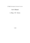
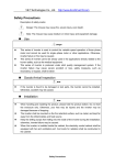
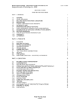
User's Manual
of
Electromagnetic Flow Meter
1
目录
Contents
03 BRIEF INTRODUCTION
04 WORKING PRINCIPLES
Measuring Principles
Converter Circuit Schematic
05 PRODUCT CLASSIFICATION
Product Components
Product Models
05 TECHNICAL SPECIFICATON
07 DRAWINGS AND DIMENSIONS
08 LECTOTYPE PRINCIPLE
12 CONVERTER OPERATION MENU AND PARAMETER SETUP
Keypad and Display
L_MagB_4 key parameters and setting
Details Parameters
22 INSTALLATION
24 WIRING
Grounding
Converter Terminals and Definition
Remote-type Wiring
Output Signal Wiring
29 SELF-DIAGNOSTICS AND TROUBLESHOOTING
30 PACKAGING
30 TRANSPORTATION AND STORAGE
30 OPERATION
2
Brief
Introduction
1.1 Features
�
�
�
�
�
�
�
�
�
Measurement is not affected by the variation of flow density, viscosity,
temperature, pressure and conductivity. High accuracy measurement is
guaranteed according to the linear measurement principle.
No obstacle in the pipe, no pressure-loss and lower requirement for
straight pipeline.
DN 6 to DN2000 covers a wide range of pipe size. A variety of liners
and electrodes are available to satisfy different flow characteristic.
Programmable low frequency square wave field excitation, improving
measurement stability and reducing power consumption.
Implementing 16 bits MCU, providing high integration and accuracy;
Full-digital processing, high noise resistance and reliable measurement;
Flow measurement range up to 1500:1.
High definition LCD display with backlight.
RS485 or RS232 interface supports digital communication.
Intelligent empty pipe detection and electrodes resistance
measurement diagnosing empty pipe and electrodes contamination
accurately.
SMD component and surface mount technology (SMT) are
implemented to improve the reliability.
1.2 Main Applications
Electromagnetic flowmeter can be used to measure the volume flow of
conductive fluid in a closed pipeline. It is widely applied in the flow
measurement and control in the fields of chemical and petroleum industry,
metallurgy industry, water and waste water, agriculture and irrigation, paper
making, food and beverage industry and pharmaceutical industry.
1.3 Ambient and Working Conditions
Ambient temperature: sensor: -25℃ to + 60℃; converter: -25℃ to + 60℃.
Relative humidity: 5% to 90%; Fluid conductivity: ≥ 5m S/cm
Maximum fluid temperature: Compact type: 60℃
Remote type: Teflon
150℃
Neoprene
80℃; 120℃
Polyurethane
70℃
3
Working Principles
2.1 Measuring Principles
The measuring principle of electromagnetic
flowmeter is based on the electromagnetic
induction law of Farady. The sensor is mainly
composed of measuring tube with isolate lining, a
pair of electrodes installed by penetration of the
measuring tube wall, a pair of coils and iron core to
produce working magnetic field. When the
conductive fluid flows through the measuring tube
of the sensor, the voltage signal in direct proportion
to the average flow velocity of the fluid will be
inducted on the electrodes. The signal is amplified
and treated by the transmitter to realize various
display functions.
1
2.2 Converter Circuit Schematic
The converters supplies a stable exciting current to the coil in the sensor
of electronetic flowmeters to get B constant and amplifies the electromotive
force and convert it into standard signals of current or frequency so that the
signals can be used for displaying, controlling and processing. The schematic
of converter circuit is shown in Fig. 2.1.
Fig. 1 Schematic of converter circuit
4
Product Classification
Electromagnetic flowmeter is composed of sensor and converter. It has two
forms: compact-type and remote-type. The remote-type also needs a special
double-layer shielded cable to connect the converter and the sensor. There
are seven kinds of electrode materials and four kinds of lining materials
available for sensor.
Technical Specifications
Peak flow rate
15 m/s
Accuracy
(refer to accuracy curve)
indication±0.5%(flow rate no less than 0.8m/s)
Conductibility of fluid
≥5μs/cm
Nominal pressure
Ambient temperature
DN15~DN150
4.0MPa
DN15~DN600
DN200~DN1000
1.6MPa
1.0MPa
DN700~DN3000
sensor
0.6MPa
-25℃~+60℃
compact flowmeter and converter
-10℃~+60℃
liner material
Remote-type
Compact-type
polytetrafluoroethylene
The liner material and
maximum temperature of
fluid
polyvinyl fluoride
fluorinated
ethylene-propylene(FEP)
polychloropree rubber
polyurethane
100℃;150℃(special
order required)
100℃;150℃(special
order required)
100℃;150℃(special
order required)
80℃;120℃(special
order required)
80℃
70℃
70℃
70℃
70℃
70℃
Electrode type
Fixed type(DN150~DN2600); Blade type(DN300~DN1600)
Material of signal electrode
and grounding electrode
mo-containing stainless steel,hastelloy B,hastelloy C,titanium
alloy,tantalum alloy, platinum-iridium alloy,stainless steel-coated wolfram
carbide
Flange Material
carbon steel
Grounding flange material
stainless steel 1Cr18Ni9Ti
5
Material of inlet protection
flange
Shell protection
Spacing(remote type)
DN15~DN600
stainless steel 1Cr18Ni9Ti
DN700~DN3000
carbon steel
DN15~DN150 remote sensor with rubber
or polyurethane liner
DN200~DN2600 remote sensor with
rubber or polyurethane liner
IP65,IP68(special order
required)
IP68 5~10m underwater
other sensor and all kinds of converter
IP65
Generally, the spacing between converter and sensor is no longer than
100 meters, special order will be required when it is longer than 100 m.
�
General Specification of Converter
Power supply: AC 85-265V, 45-63Hz, ≤20W; DC 11-40V
Converter display and operation: four keys are available to set all
parameters. External handheld or PC can be used to do the configuration.
High resolution LCD display with backlight, empty pipe detection and
self-diagnostic function are equipped in the converter.
Digital communication: RS485, RS232, MODBUS,REMOTE
Output Signals:
- Current output: fully-isolated, 4-20mA/0-10mA
load resistance: 0-10mA: 0-1.5KΩ; 4-20mA: 0-750Ω.
- Frequency output: bidirectional flow output. Frequency output is
proportional to the flow percentage of the full range. The converter provides
fully isolated transistor open collector frequency output ranged from 1 to 5000
Hz. The external DC power supply should not exceed 35V and maximum
collector current is 250mA.
- Pulse output: bidirectional flow output. The converter can output up to
5000cp/s pulse series, which is dedicated to external totalization. Pulse factor
is defined as volume or mass per pulse. It can be set to 0.001L/p, 0.01L/p,
0.1L/p, 1L/p, 2L/p, 5L/p, 10L/p, 100L/p, 1m 3/p, 10 m 3/p, 100 m3/p or 1000 m3/p.
Pulse width is selectable from auto, 10ms, 20ms, 50ms, 100ms, 150ms,
200ms, 250ms, 300ms, 350ms and 400ms. Photo-coupler isolated transistor
open collector circuit is used for pulse output. The external DC power supply
should not exceed 35V and maximum collector current is 250mA.
- Flow direction indication: The converter is capable of measuring both
forward and reverse flow and recognizing its direction. The converter outputs
0V low level for forward flow, while +12V high level for reverse flow.
- Alarm output: Two channels of photo-coupler isolated open collector
circuit are used for alarm signal output. There are two alarm outputs: high limit
alarm and low limit alarm. The external DC power supply should not exceed
35V and maximum collector current is 250mA.
- Damping constant: Damping time is selectable from 0.2 to 100s.
6
Drawings and Dimensions
7
Lectotype principle
The measured fluid must be conducting liquid or slurry with a conductibility
no less than 5μs/cm, avoid fluid with too much ferromagnetic substance or
bubble. The pressure rating, liner material, electrode material and instrument
structure should be chosen based on the characteristics of the fluid.
Selection of nominal diameter
1. As electromagnetic flowmeter has a high rangeability of 1500:1, the
selection of nominal diameter is the same as that of process pipe;
2. If there are solid particle in the measured medium, a flow rate range of
1~3m/s is recommended. If the practical flow rate is excessive yet
inconvenient to adjust, the nominal diameter of the instrument is better
larger than that of the process pipe, under which condition the flow rate in
the measuring pipe of the flowmeter can be properly decreased and the
abrasion of electrode and liner caused by the particle can be alleviated;
3. If there are sediment in the process pipe, a flow rate range of 1~3m/s is
recommended. If the practical flow rate is too little, the nominal diameter of
the instrument is better smaller than that of the process pipe in order to
properly increase the flow rate of the fluid in the flowmeter to avoid the
effect on the accuracy caused by the sediment.
4. If the flow rate is too little yet a high-precision measurement is required, a
sensor smaller than the nominal diameter can increase the flow rate to
ensure high precision.
In the above 2,3,4 conditions, a reducing pipe should be jointed to both
the upstream and downstream of the flowmeter. The centre taper angle should
be no more than 150 and there should be a straight pipe at least 5 times of the
the process pipe jointed to the reducing pipe.
To help making lectotype, several flow values which corresponding to the
certain typical flow rate are listed in the table below, any flow value could be
quickly work out based on the corresponding flow rate: If a flow value is known
as Q(m 3/h), according to the relevant nominal diameter, check out the
corresponding flow value Q1 with a flow rate of 1m/s, then the flow rate can be
work out through a formula as V=Q/Q 1(m/s).
8
comparison table of flow and flowrate
Flow rat e m/s
Flow m 3 /h
0.01
(Min.)
1
2
3
4
5
15
(Max.)
0.0064
0.0113
0.0177
0.452
0.0707
0.1195
0.1810
0.2827
0.6362
1.1310
1.7671
2.5447
3.4636
4.5239
5.7256
7.0686
10.1788
13.8544
18.0956
22.9022
28.2743
40.71.50
55.4177
72.3823
91.6088
113.0973
136.8478
162.8602
191.1343
0.6362
1.1310
1.7671
4.5239
7.0686
11.9459
18.0956
28.2743
63.6173
113.0973
176.7146
254.4690
346.3606
452.3893
572.5553
706.8583
1017.8760
1017.8760
1385.4424
1809.5574
2290.2210
2827.4334
4071.5041
5541.7694
7238.2295
9160.8842
11309.7336
16286.0163
19113.4268
1.2723
2.2619
3.5343
9.0478
14.1372
23.8918
36.1911
56.5487
127.2345
226.1947
353.4292
508.9380
692.7212
904.7787
1145.1105
1413.7167
2035.7520
2770.8847
3619.1147
4580.4421
5654.8668
8143.0082
11083.5389
14476.4589
18321.7684
22619.4671
27369.5552
32572.0326
38226.8536
1.9085
3.3929
5.3014
13.5717
21.2058
35.8377
54.2867
84.8230
190.8518
339.2920
530.1438
763.4070
1039.0818
1357.1680
1717.6658
2120.5750
3053.6281
4156.3271
5428.6721
6870.6631
8482.3002
12214.5122
16625.3083
21714.6884
27482.6525
33929.2007
41054.3328
48858.0490
57340.2804
2.5447
4.5239
7.0686
18.0956
28.2743
47.7836
72.3823
113.0973
254.4690
452.3893
706.8583
1017.8760
1385.4424
1809.5574
2290.2210
2827.4334
4071.5041
5541.7694
7238.2295
9160.8842
11309.7336
16286.0163
22167.0778
28952.9179
36643.5367
45238.9342
54739.1104
65144.0653
76453.7072
3.1809
5.6549
8.8357
22.6195
35.3429
59.7295
90.4779
141.3717
318.0863
565.4867
883.5729
1272.3450
1731.8030
2261.9467
2962.7763
3534.2917
5089.3801
6927.2118
9047.7868
11451.1052
14137.1669
20357.5204
27708.8472
36191.1474
45804.4209
56548.6678
68423.8880
81430.0816
95567.1340
9.5426
16.9646
26.5072
67.8584
106.0288
179.1886
271.4336
424.1150
954.2588
1696.4600
2650.7188
3817.0351
5195.4089
6785.8401
8588.3289
10602.8752
15268.1403
20781.6354
27143.3605
34353.3157
42411.5008
61072.5612
83126.5416
108573.4421
137413.2627
169646.0033
205217.6640
244290.2448
286701.4020
Diameter mm
15
20
25
40
50
65
80
100
150
200
250
300
350
400
450
500
600
700
800
900
1000
1200
1400
1600
1800
2000
2200
2400
2600
9
Selection of liner material
Liner material
polytetrafluoro
ethylene
polychloropre
e rubber
polyurethane
rubber
Main performances
1.It is a plastic material with the stablest chemical
properties, resist the corrosion of boiling
hydrochloric acid, sulfuric acid, nitric acid, aqua
regia, concentrated alkali and many kinds of
organic solvent, unable to resist the corrosion of
chlorine
trifluoride,
high
temperature
vanadyltrifluoride, high flow-rate liquid fluorine,
liquid oxygen and ozon;
2.Poor abrasion resistance;
3.Poor ability of anti-negative pressure.
1.Excellent elasticity, high degree of tensile
strength, good wear resistance;
2.Able to resist the corrosion of generally low
concentration acid, alkali and salt, unable to resist
that of the oxidative medium.
1.Excellent wear resistance(ten times of the natural
rubber’s);
2.Poor abrasion resistance of acid and alkali;
3.Not able to work with water mixed with organic
solvent.
Applicability
1.100℃ , 150℃(special
order required);
2.Strong
corrosive
medium like concentrated
acid , alkali, etc.;
3.Sanitary medium.
1.80℃,120℃(special
order required);
2.General water, polluted
water, weak wear ability
mud and ore pulp.
1.<80℃;
2.Middle and strong wear
ability ore pulp, coal pulp,
mud, etc..
Selection of electrode material
Materials of electrode
Corrosion resistance
Mo-containing stainless
steel
(0Cr18Ni12Mo2Ti)
Stainless steel-coated
wolfram carbide
Able to work with medium with weak corrosivity, such as
industrial water, living water, polluted water, etc., widely used
in industries like oil, chemical, urea, vinylon, etc..
Hastelloy B(HB)
Hastelloy C(HC)
Used for medium without corrosivity or with weak wear ability.
Good corrosion resistance of different concentration of
hydrochloric acid under boiling point, resist the corrosion of
non-oxidizing acid, alkali, non-oxidizing salt solution, such as
sulfuric acid, phosphoric acid, organic acid, etc..
Resist the corrosion of oxidizing acid, such as nitric acid,
mixed acid, the mixture of chromic acid and sulfuric acid,
oxidizing salt like Fe+++, Cu++ or other oxidants such as
hypochlorite solution above ordinary temperature and
seawater.
10
Titanium(Ti)
Tantalum(Ta)
Platinum-iridium alloy
Resist the corrosion of seawater, all kinds of chloride,
hypochlorite, oxidizing acid(include fuming nitric acid), organic
acid, alkali, etc., unable to resist the corrosion of purer
reducing acid like sulfuric acid and hydrochloric acid. The
corrosivity of alpha hydroxy acids will be substantially
decreased if there are oxidants such as nitric acid, Fe+++,
Cu++ , etc. in it.
The corrosion resistance of tantalum is as good as glass.
Except hydrofluoric acid, fuming nitric acid and alkali, it is able
to resist the corrosion of almost any other chemical media.
Almost be able to work with any chemical medium other than
aqua regia and ammonium salt.
As there is a great variety of medium and their corrosivity can be affected
by complexity factors such as temperature, concentration, flow rate, etc., the
above two tables are just for reference. Customers should make choices
according to the practical situations, if necessary, corrosion resistance
experiment like hanging sheet experiment of simulation materials should be
performed.
Selection of
liner protection flange and grounding flange
Type of flange
Applicability
Grounding flange
Applicable to non-conductive pipeline like
plastic pipeline. However, it is not required for
the sensor with polytetrafluoroethylene liner.
Inlet protection flange
Applied when the medium has strong wear
ability, often used with polyurethane liner.
However, it is not applicable to the sensor with
polytetrafluoroethylene liner.
11
Convertor Operation Menu and
Parameter Setting
6.1 Keypad and Display
Fig.5(a) Remote-type key and display
Fig.5(b) Compact-type key and display
12
6.2 L_MagB_4 key parameters and setting
When electrify, the instrument comes into measure way automatically, and
under this way it can do all the functions and display data. Under the
parameter setting way, user can set the parameter by the four keys.
5.2.1 Keys function
a) Keys
Keys’’ function in self- testing way
“Down” key: Selecting displayed data on lower line in turn;
“Up” key: Selecting displayed data on higher line in turn;
“Compound” key + “Enter” key: Come into parameter setting
“Enter” key: Press it to come into the picture of select function.
Under the measure, adjust of the LCD contract is used “Compound” key +
“Up” key or “Compound” key + “Down” key for several seconds;
b) Function keys for parameters setting
“Down” key: Subtract 1 from the number at cursor area;
“Up” key: Plus 1 to the number at cursor area;
“Compound” key + “Down” key: Cursor turns left;
“Compound” key + “Up” key: Cursor turns right;
“Enter” key: In/Out
submenu;
“Enter” key: Press for two seconds under any state and will return to
automate measure way.
Note: (1)When use “Compound” key, you should press “Compound” key and
“Up” or
“Down” both;
(2) It will return to the measure way automatically after 3 minutes
when under the parameter setting way;
(3) Direct select of zero correction about the flow, you can move the
cursor to the left + or - , and use “Down” or “Up” to switch;
6.2.2 Function keys for setting parameters
To set or correct working parameters, the converter should be running in
parameters setting way instead of measuring status. In measuring status, push
“Compound”+“Enter” keys getting to the select of parameter and transfer
password (0000), and then correct the password with one of the new
passwords that are provided by manufacturer. Finally, push the
“Compound”+“Enter” keys to work in Parameters Setting Way.
There are 6 Passwords in design and among them 4 for deferent operators
in secret and 2 are fixed passwords for system operation.
6.2.3. Functions select menu
Push “Compound”+“Enter” keys to the functions select menu, push “Up” or
“Down” keys to select, there are two functions:
Code
Functions
Notes
1
Parameters
Select this function; It can enter the
13
Set
2
Clr Total Rec
3
Fact Modif
Rec
picture of parameter.
Select this function,It can be gross
reset operation.
Select this function, It can be check
the factor ‘s modif Record
6.2.3.1 Parameters Set
Press “Compound”+“Enter” key, it displays “Parameters Set” function.
Input password. Press “Compound”+“Enter” key, it getting to Parameters
Setting status.
6.2.3.2 Clr Total Rec
To push “Compound”+“Enter” keys getting to the select of parameter, then
push “Up” key to “Clr Total Rec”, input the passwords. When the passwords
becomes “00000”, this function is done, the gross is 0 in the instrument.
6.2.3.3 Fact Modif Rec
To push “Compound”+“Enter” keys getting to the select of parameter, then
push “Up” key to “Fact Modif Rec”(Detail consult the AppendixFive)
6.2.4 Setting Parameters in Menu
There are 54 parameters of L_MagB, user can set every parameter. The
List of Parameters is shown below:
Setting Parameters in Menu
Parameter
Setting
Code
Grades
Range
words
Way
1
Language
Select
2
English
2
Comm Addres
Set count
2
0~99
3
Baud Rate
Select
2
600~14400
4
Snsr Size
Select
2
3~3000
L/h、L/m 、L/s、m 3/h 、
5
Flow Unit
Select
2
m 3/m、m3/s
6
Flow Range
Set count
2
0~99999
7
8
9
10
11
Flow Rspns
Flow Direct
Flow Zero
Flow Cutoff
Cutoff Ena
Select
Select
Set count
Set count
Select
2
2
2
2
2
12
Total Unit
Select
2
13
14
15
SegmaN Ena
Analog Type
Pulse Type
Select
Select
Select
2
2
2
16
Pulse Fact
Select
2
17
Freque Max
Select
2
1~50
Plus/ Reverse
0~±9999
0~599.99%
Enable/Disable
0.001m3~1m3 、
0.001L~1L、
Enable/Disable
0~10mA /4~20mA
Freque / Pulse
0.001m3~1m3 、
0.001L~1L、
1~ 5999 HZ
14
18
19
20
21
22
23
24
25
26
27
28
29
30
31
32
33
34
35
36
37
38
39
40
41
42
43
44
45
Mtsnsr Ena
Mtsnsr Trip
Alm Hi Ena
Alm Hi Val
Alm Lo Ena
Alm Lo Val
Sys Alm Ena
Clr Sum Key
Snsr Code1
Snsr Code2
Field Type
Sensor Fact
Line CRC Ena
Lineary CRC1
Lineary Fact 1
Lineary CRC2
Lineary Fact 2
Lineary CRC3
Lineary Fact 3
Lineary CRC4
Lineary Fact4
FwdTotal Lo
FwdTotal Hi
RevTotal Lo
RevTotal Hi
PlsntLmtEna
PlsntLmtVal
Plsnt Delay
Select
2
Enable/Disable
Set count
2
59999 %
Select
2
Enable/Disable
Set count
2
000.0~ 599.99 %
Select
2
Enable/Disable
Set count
2
000.0~599.99 %
Select
2
Enable/Disable
Set count
3
0~99999
User set
4
Finished Y M
User set
4
Product number
Select
4
Type1,2,3
Set count
4
0.0000~5.9999
Select
4
Enable/Disable
User set
4
Set Velocity
User set
4
0.0000~1.9999
User set
4
Set Velocity
User set
4
0.0000~1.9999
User set
4
Set Velocity
User set
4
0.0000~1.9999
User set
4
Set Velocity
User set
4
0.0000~1.9999
Correctable
5
00000~99999
Correctable
5
00000~9999
00000~99999
Correctable
5
Correctable
5
00000~9999
Select
5
Enable/Disable
Select
5
0.010~0.800m/s
Select
5
400~2500ms
User
46
Pass Word 1
5
00000~99999
correct
User
00000~99999
47
Pass Word 2
5
correct
User
48
Pass Word 3
5
00000~99999
correct
User
49
Pass Word 4
5
00000~99999
correct
50
Analog Zero
Set count
5
0.0000~1.9999
51
Anlg Range
Set count
5
0.0000~3.9999
52
Meter Fact
Set count
5
0.0000~5.9999
53
MeterCode 1
Factory set
6
Finished Y /M
54
MeterCode 2
Factory set
6
Product Serial No
Parameters of converters can decide the running status, process and
output ways as well as state of output. Correct option and setting of
15
parameters can keep the converters running optimally and get higher
accuracies of output bother in display and in measurement.
There are 6 grades of passwords for setting parameters function. Grades
1 to grade 5 of passwords are for users and grade 6 of password is for
manufacturer. Users can reset their passwords of grades 1~4 in grade 5.
Users can check converters parameters in any grade of password. However,
if users want to change parameters pf converters, deferent grade of
parameters have to be used by the users.
Grade 1 of password (set by manufacturer as 00521): users can only read
parameter.
Grade 2 of password (set by manufacturer as 03210): users can change
1~24 parameters.
Grade 3 of password (set by manufacturer as 06108): users can change
1~25parameters.
Grade 4 of password (set by manufacturer as 07206): users can change
1~38parameters.
Grade 5 of password (Fixed): users can change 1~52 parameters.
Password Grade 5 can be set by skilled users. Grade 4 is mainly used for
resetting total volume in password. Grades 1~3 can be set by any one who can
be chosen by users.
6.3 Details Parameters
6.3.1 Language
There are 2 languages for L_MagB converter operation. They can be set
by users according to the users needs.
6.3.2 Comm Addres
It means this instrument’s address when communicates with many, and
has 01~99, holding the 0.
6. 3.3 Baud Rate
600, 1200, 2400, 4800, 9600, 19200, baud rate.
6.3.4 Snsr Size
L_MagB converters can be equipped with some deferent sensors that
have deferent diameter of measuring pipes. The pipes in deferent diameters
from 3mm to 3000mm can be chosen in relative table.
6.3.5 Flow unit
The flow unit can choose form the parameters (L/s、L/m、L/h、m 3/s、m3/m、
m3/h),and the user can choose the proper unit according to the technological
requirement and using habit.
6.2.6 Flow Range
Flow range means upper limit value, and lower limit value is set “0”
automatically. So, it makes the range, and makes the relation of percent
display, frequency output and current output with flow:
percent display = ( flow measure / measure range) * 100 %;
frequency output = ( flow measure / measure range) * frequency full;
16
current output = ( flow measure / measure range) * current full + base
point;
pulse output will not affect.
6.3.7 Flow Rspns
It means time of filter measure value. The long one can enhance the
stability of flow display and output digital, and fits for gross add up of pulse flow;
the short one means fast respond rate, and fits for production control. It is set
by select.
6.3.8 Flow Direct
If users think the direct and design are differ, just change the direct
parameter is OK, but not change exciting or signal.
6.3.9 Flow zero
Make sure the sensor is full of flow, and the flow is stillness. Flow zero is
shown as velocity of flow, mm/s.
FS = ○ ○ ○ ○ ○
± ○ ○ ○ ○ ○
Converter ’s zero-flow
correction displays like
this:
Upper small words: FS means measure value of zero;
Lower large words: correction value of zero.
When FS is not “0”, make FS = 0. Note: if change the value on next line
and FS increases, please change the “+, -” to correct FS to zero.
Flow zero is the compound value of the sensor, and should be recorded in
sensor list and band. The unit will be mm/s, and the sign will be opposite with
correction value.
6.3.10 Flow cutoff
Flow cutoff is set in percentage of Upper Limit Range of flow, and users
can delete all Negligible Small Signals of flow volume, velocity and percentage
out of displaying and outputting them. Sometimes user can delete output of
current output signal and frequency (pulse) output signal only to have flow,
velocity and percentage being displayed
6.3.11 Total Unit
Converter display is counter with 9 bits, and the max is 999999999.
Integrator units are L, m 3 (liter, stere,).
Flow integrator value: 0.001L、 0.010L、 0.100L、 1.000L
0.001m3、 0.010m3、 0.100m 3、 1.000m 3 ;
6.3.12 SegmaN Ena
When “SegmaN Ena” is “enable”, if the flow flows, the sensor will export
pulse and current。When it is “disable”, the sensor will export pulse as “0” and
current as “0”(4mA or 0mA) for the flow flows reversals.
6.3.13 Output currents
Output current types can be chosen by users as 1~10mA or 4~20mA
17
practically.
6.3.14 Pulse Type
Two kinds of Pulse Outputs are can be chosen: Frequency Output and Pulse
Output. Frequency Output is continuous square waveform and Pulse output is
a serial wave of square wave. Frequency output is mainly used for instant flow
and total integrated flow in short time measurement. Frequency output can be
chosen in equivalent frequency unit and volume of integrated flow can be
displayed. Frequency Output can be used in long time measurement for total
integrated flow with volume units.
Frequency output and pulse output are usually from OC gates so that DC
power supplies and load resistors have to be required (See Part 4.5).
6.3.15 Pulse Fact
Equivalent pulse Unit is referred to one pulse for value of flow. The range
of pulse equivalent can be chosen:
Pulse
Pulse
Equivale
Flow
Equivale
Flow
nt
nt
1
0.001L/cp
5
0.001m3/cp
2
0.01L/cp
6
0.01m3/cp
3
0.1L/cp
7
0.1m3/cp
4
1.0L/cp
8
1.0m3/cp
Under the same flow, the smaller pulse, the higher frequency output, and
the smaller error will be. The highest pulse output is 100cp/s, and mechanism
electromagnetic counter can get 25 frequency/s.
6.3.16Freque Max
Frequency output range is as the upper limit of flow measure, just the
percent flow 100%. Frequency output upper limit can be selected between 1~
5000Hz.
The state of empty pipe can be detected with the function of converter. In
the case of Empty Pipe Alarm, if the pipe was empty, the signals of analog
output and digital output would be zero and displayed flow would be zero, too.
6.3.17Mtsnsr Ena
The state of empty pipe can be detected with the function of converter. In
the case of Empty Pipe Alarm, if the pipe was empty, the signals of analog
output and digital output would be zero and displayed flow would be zero, too.
6.3.18Mtsnsr Trip
When the pipe is full of liquid (whether flowing or not), the parameter of
“Mtsnsr” could be modified more easily. The parameter displayed upper line is
real MTP, and the parameter displayed bellow is the “Mtsnsr trip” that should
be set. When setting “Mtsnsr trip”, you could be according to the real MTP, the
value that should be set is usually three to five times of real MTP.
6.3.19 Alm Hi Ena
Users can choose “Enable” or “Disable”.
6.3.20 Alm Hi Val
18
The parameter of upper limit alarm is percentage of flow range and can be
set in the way of setting one numerical value between 0%~199.9%.When the
value of flow percentage is larger than the value of setting value, the converter
outputs the alarm signal.
6. 3.21Alm Lo Val
The same as upper limit alarm.
6.3.22 Sys Alm Ena
Selecting Enable will have the function, and selecting Disable will cancel
the function.
6.3.23 Clr Sum Key
User use more than 3 byte code to enter ,Then set this password in Clr
Total Rec.
6.3.24 Snsr Code
It is referred to the produced date of sensor and the serial number of
product that can keep the sensors coefficient right and accurate.
6.3.25 Sensor Fact
“Sensor Coefficient” is printed on the Label of the sensor when it is made
in factory. The “sensor coefficient” has to be set into Sensor Coefficient
Parameter when it runs with converter.
6.3.26 Field Type
L_MagB affords three exciting frequency types: 1/16 frequency (type 1),
1/20frequency (type 2), 1/25 frequency (type 3)。 The small-bore one should
use 1/16 frequency, and large-bore one should use 1/20 or 1/25 frequency.
When using, please select type 1 first, if the zero of velocity is too high, select
the type 2 or type 3.
Note: Demarcate on which exciting type, working on it only.
6.3.27 FwdTotal Lo、hi
Positive total volume high byte and low byte can change forthcoming and
reverse total value, and be used to maintenance and instead.
User use 5 byte code to enter, and can modify the positive accumulating
volume (∑+). Usually, it is unsuitable to exceed the maximum the counter set
(999999999).
6.3.28 RevTotal Lo、hi
User use 5 byte code to enter, and can modify the negative accumulating
volume (∑-). Usually, it is unsuitable to exceed the minimum the counter set
(999999999).
6.3.29 PlsntLmtEn
For paper pulp, slurry and other serosity, the flow measure will have
"cuspidal disturb", because the solid grain friction or concussion the measure
electrode. L_MagB converters use variation restrain arithmetic to conquer the
disturbing by designing three parameters to select disturb character.
Set it "enable", start variation restrain arithmetic; set it "disable", close
variation restrain arithmetic.
19
6.3.30PlsntLmtVl
This coefficient can disturb the variation of cuspidal disturb, and calculate
as percent of flow velocity, thus ten grades: 0.010m/s, 0.020m/s, 0030m/s,
0.050m/s, 0.080m/s, 0.100m/s, 0.200m/s, 0.300m/s, 0.500m/s, 0.800m/s, and
the smaller percent, the higher delicacy of cuspidal restrain.
Note: when using it, must test for select by the fact, and sometimes it is
not the higher delicacy is good.
6.3.31 PlsntDelay
This coefficient can select the width of time of restrain cuspidal disturb and
the unit is ms. If the duration is shorter than flow change in some time, L_MagB
will think it is cuspidal disturb, and if it is longer, L_MagB will think it is natural.
It also needs to select parameter in fact.
6.3.32User ’s password 1~4
Users can use 5 grades of passwords to correct these passwords.
6.3.33 Analog Zero
When the converters are made in the factory, output current has been
calibrated to zero scale, that is, accurate 0mA or 4mA output.
6.3.34 Anlg Range
When the converters is made in the factory, output current have been
calibrated to full scale, that is, accurate 10mA or 20mA output.
6.3.35Meter Fact
This fact is the special one of sensor-made-factory and the factory use this
fact to unite L_MagB electromagnetic flowmeters converters to make sure all
the instruments can interchange by 0.1%.
6.3.36 MeterCode 1 and 2
Converter code records the date of manufacturing and serial number of
converter
20
Installation
21
22
Wiring
8.1 Grounding
Sealing
Gasket
23
8.2 Converter Terminals and Definition
Terminal blocks and marks are shown in Fig. 8 and Fig. 9
Fig. 8 Remote Type: Terminals and Marks
The definition of terminals and their marks for remote type converter is given
as below:
DS1
SIG1
Shield drive 1
Signal input 1
SIG GND
SIG2
Signal Ground
Signal input 2
DS2
EXT+
EXT-
Shield drive 2
Coil excitation +
Coil excitation -
IOUT
ICOM
Current output +
Current output -
PUL+
PCOM
Frequency/pulse output +
Frequency/pulse output -
PDIR
ALM-
Flow direction indicator +
Low alarm output +
ALM+
ALCOM
High alarm output +
Alarm output -
A
B
RS485 communication A
RS485 communication B
IN+
IN-
Input contact +
Input contact -
L1(+)
L2(-)
220V(24V +) input
220V(24V -) input
The dip switch SW1 is set to ON to supply +12V power to pulse output. If
24
external power is used, turn the switch to OFF.
Fig. 9 Compact Type: Terminals and Marks
The definition of terminals and their marks for compact type converter is
given as below:
T-
RS485-B
T+
RS485-A
COM
Alarm/flow direction/ pulse output -
FDIR
Flow direction indicator +
AL
Low alarm output +
AH
High alarm output +
IN-
Input contact -
IN+
Input contact +
P+
Frequency/pulse output +
COM
Current/pulse output -
I+
Current output +
L1(+)
220V(24V +) input
L2(-)
220V(24V -) input
25
8.3 Remote-type Wiring
8.3.1 Terminal Block in Sensor
Fig. 11 Marks of Terminal Block
SIG1: Signal 1 (Connecting to white coax wire ofSTT3200 cable)
SIG2: Signal 2 (Connecting to black coax wire of STT3200 cable)
DS1: Signal 1 shield drive (Connecting to inner shield layer of white coax
wire of STT3200 cable)
DS2: Signal 2 shield drive (Connecting to inner shield layer of black coax
wire of STT3200 cable)
SIG GND: Signal ground (Connecting to Ex-shield of STT3200 cable)
EXT+: Coil 1 (Connecting to red cable)
EXT-: Coil 2 (Connecting to yellow cable)
8.3.2 Connection of STT3200 Cable
Fig. 13 Schematic Diag for STT3200 Cable Preparation
26
8.4 Output Signal Wiring
The dip switch SW1 is set to ON to supply +12V power to pulse output. A
1KΩ resister is connected to the +12V power to provide a pull-up. If external
power is used, turn the switch to OFF.
DC Power Electrom agnetic
C ounter
S upply
+ 123 456
IC O M
PCO M
+
IO U T
-
P O U T+
A mmeter
Fig. 14(a) Wiring of current output
Fig.14 (b) Example of electromagnetic
counter connection
123456
L1
L2
PC O M
IO U T +
IN +
PU L +
Fig. 14(c) Example of electrical counter connection
Fig. 14(d) Digital Output Direct Connection
27
PUL+
R
Internal
Circuit
+
E
-
User
Device
PCOM
Fig. 14(e) Connection with photo-coupler (e.g. PLC)
J
PUL
+
+
Internal
E
Circuit
D
-
PCO
M
Fig.14 (f) Connection with relay (e.g. PLC)
Generally, the intermediate relay needs 12V or 24V power supply E. D is a
surge-absorbing diode, which is usually embedded in the relay. If not, an
external one is necessary.
28
Self-diagnostic and Troubleshooting
The converter is made by surface mount technology and is not repairable
for user. Do not open the converter case.
The self-diagnosis function of the converter is capable of displaying alarm
information except power supply or hardware failures. A ‘!’ symbol is displayed
on the right corner of LCD top-line and malfunction information can be read
from the bottom-line by pressing DOWN key. User may check the flowmeter
according to the alarm information. Some examples of alarms are given below:
Coil Alm
Elctrd Alm
EpPipe Alm
Low Alarm
High Alarm
Troubleshooting information is given below:
9.1 No display
a) Check the connection of power supply;
b) Check fuse;
c) Check the voltage of power supply;
d) Check if the LCD contrast can be adjusted. Adjust it if possible;
e) Return to base, if a) to d) are OK.
9.2 Coil Alarm
a) Check if terminal EXT+ and EXT- are open;
b) Check if coil resistance is less than 150Ω;
c) Replace converter if a) and b) are OK.
9.3 Empty Pipe Alarm and Electrodes Alarm
a) Check if the sensor pipe is filled with fluid;
b) Check the connection of signal wiring;
c) Connect the terminal SIG1, SIG2 and SIG GND. If the alarm display
disappears, it is confirmed the converter is normal. The alarm may be
caused by the bubble in the fluid;
d) For electrodes alarm, measure the resistance between two electrodes
with a multimeter. The read should be between 3 to 50kΩ. Otherwise,
the electrodes are contaminated or covered.
9.4 High Alarm
Increase the flow range.
9.5 Low Alarm
Reduce the flow range.
9.6 Inaccurate Measurement
a) Check if the sensor pipe is filled with the fluid to be measured.
29
b) Check the wiring;
c) Check if the sensor factor and flow zero are the same as those on the
calibration sheet.
Packing
The package includes:
The electromagnetic flowmeter ordered;
Instruction Manual;
Transportation and Storage
To prevent the flowmeter from damage in the transportation, the package
should be kept in unopened status before reaching installation site. The
storage room should be satisfied with the following conditions:
a. Rain-proof, humidity-proof;
b. Strong Vibration and Shake Avoidance
c. Temperature between -20 to +60℃, relative humidity less than 80%
Operation
Before operation, the following inspection should be done to check if:
a. There is any damage caused by transportation or installation;
b. The power used is same as the label on the flowmeter;
c. The wiring is correct.
After inspection, turn the valve on to fill the pipe up and make sure there is
no leakage and the gas inside the pipe is eliminated. Switch on the power
supply and the flowmeter is ready to use after 10 minutes warm-up.
If there is any problem, please refer to the Section 9 for troubleshooting. If still
not working properly, contact the manufacturer immediately.
30