1
FM4200 Sample Advanced User Guide
1 About the document
This document contains information about testing the FM4200 samples and configurations
commonly used in such cases.
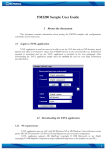
1.1 Login to TAVL application
TAVL application is used for users to be able to see the AVL data such as GPS location, speed,
ignition and other I/O elements’ values from FM4200 devices in the users-friendly way. Information
required to download and use the TAVL application is provided in the next paragraph. After
downloading the TAVL application simply open the tavl.exe file and use your login information
provided below.
Client username
Client password
Client_name
Pic. 1. Login to TAVL application
1
1.2 Downloading the TAVL application
1.2.1 PC requirements
TAVL application runs on a PC with MS Windows XP or MS Windows Vista with latest service
packs. MS .NET Framework v3.5 SP1 and Crystal Reports are also necessary components.
TAVL application supports MS MapPoint (copyright © 2008 Microsoft) or any MapX
(copyright © 2008 MapInfo Corporation) maps (additional maps have to be installed on users PC).
1.2.2 .NET Framework installation
Download .NET Framework 3.5 SP1 from Microsoft website and install it ( url:
http://www.microsoft.com/downloads/thankyou.aspx?familyId=ab99342f-5d1a-413d-831981da479ab0d7&displayLang=en,
mirror: http://avl1.teltonika.lt/downloads/tavl/Framework/dotnetfx35setupSP1.zip ). If the
download doesn't start automatically, click on the "Start Download" button.
1.2.3 Crystal Reports installation
Download and install Crystal Reports for .NET Framework ( url:
http://avl1.teltonika.lt/downloads/tavl/Crystal%20Reports/CRRedist2005_x86.zip ).
1.2.4 TAVL application installation
Downloads and extract latest available version of TAVL application ( url:
http://avl1.teltonika.lt/Downloads/tavl ).
Note, that if any additional information about the usage of the TAVL application is needed, please see
the latest „TAVL3 Application User Manual“.
2
2 Getting started with FM4200 device
This paragraph contains the information needed to successfully launch and use the FM4200
device. The steps below should be followed carefully to completely test the FM4200.
2.1 SIM card insert scheme
Pic. 2. Illustration of how to insert the SIM card
3
2.2 Power source connection
(-) EXT. BAT
OUT 2
OUT 3
AIN 2
AIN 4
DIN 2
DIN 4
1W. PWR
CAN L
(-)GND
10
9
8
7
6
5
4
3
2
1
20
19
18
17
16
15
14
13
12
11
(+) EXT. BAT
OUT 1
OUT 4
AIN 1
AIN 3
DIN 1
DIN 3
1W. data
CAN H
(+)VCC (10…30) V DC
Pic. 3. Standard FM4200 2x10 socket pinout
The external 10...30 V DC (12 W Max) power supply must be used to power up the device.
Connect power supply to 1 pin and 11 pin as shown above.
2.3
Placement of GPS antenna
•
•
•
GPS antenna must be placed so its state is as horizontal as possible (if antenna is leaning more
than 30 degrees, it is considered incorrect mounting).
GPS antenna cable cannot be bent more than 80 degrees.
GPS antenna must be placed sticker facing down
Pic. 4. GPS antenna correct mounting
It is recommended to place GPS antenna as close to the window as possible.
NOTE, that most of modern office windows are equipped with filters that could block GPS signal so
for best GPS signal quality we recommend to put GPS antenna outside (on windowsill, some plate
etc.).
4
2.4 Connect FM4200 to the computer
FM4200 Configuration is performed via FM4200 Configurator program. Latest FM4200
Configurator versions can be downloaded from http://avl1.teltonika.lt/downloads/FM42. FM4200
configurator operates on Microsoft Windows OS and uses MS .Net Framework 2.0 or higher. Please
ensure that MS .Net Framework 2.0 or higher is installed on your PC before starting configurator.
Latest MS .Net Framework version can be downloaded from official Microsoft web page.
Module configuration is performed over cable labeled PORT1/2. Configuration process starts
from loading FM4200 Configurator program and selecting COM port. Select COM port and click
“Connect” button. If connection is successful then instead of “Connect” appears “Disconnect” button.
Pic. 5. Connect FM4200
2.5 Loading the Configuration into the FM4200 Device
FM4200 Configurator must be used to configure the FM4200 device. Using the configurator
prepared Sample Configurations can be uploaded into the FM4200 or custom device configuration can
be made.
Pic. 6. Configuration toolbar view
5
Configuration files for all Sample Scenarios (described in 3 paragraph) are allready prepared by
Teltonika. Open the FM4200 Configurator software, select correct COM port and click on “Load from
File…” button (1) from the main toolbar. Browse for the required configuration file and click OK.
Enter the APN parameters into the GPRS section of the configuration according to the instructions
described in 2.5.1 paragraph. Click on “Save to Flash” and “Flash no. 3” buttons (2-3) to upload the
configuration into the FM4200 device.
FM4200 has 4 user editable profiles stored in Flash no. 1-4 memories and one extra profile stored
in Flash no. 0 which can not be edited by user. Profile from Flash no. 0 is used by system and can not
be selected as active, while profiles from Flash no. 1-4 are fully editable and can be selected as active.
Please note, that by default FM4200 works in 3 profile, so you must save configuration into 3 profile.
To check the current FM4200 configuration click on “Read from Flash 3” (4-5) buttons. To save
the modified configuration click on “Save to File…” button (6) and the configuration will be saved into
the file with “.xml” extension. The saved configuration will be able to upload into any FM4200 device
in the same way as described above.
Click on the button “Get actual profile” (7) – and you will see currently used profile number.
Pic. 7. Actual profile notification
2.5.1 APN configuration
In order to FM4200 device to be able to connect to local GPRS network (and send AVL data)
the following APN data (provided by local GSM services provider) must be entered into FM4200
configuration:
• Acces Point Name (APN) with authentication type CHAP or PAP (if required);
• APN login;
• APN password;
Sample below is of GPRS configuration of German “EPLUS” GSM service provider:
Pic. 8. GPRS configuration
6
3 Advanced sample scenarios
This section of the document describes the commonly used FM4200 testing scenarios and helps
users to perform the detailed testing of the FM4200 device. Below you will find the descriptions of the
sample scenarios and the configuration for each case.
3.1 Profile change on event
One of the most widely used advanced FM4200 testing scenarios is testing the device in the
“Profile change on event”. Working in such scenario the position of the object is very detailed when it
is moving or ignition is ON. When device not move 10 minutes or DIN1 is OFF then it change profile
from 1 to 3 and after 5 minutes if it not move goes to deep sleep mode. Moreover, you can monitor
which driver drives the vehicle and how much fuel driver used.
3.1.1 Configuration
To test the event based “Profile change on event” scenario please load the prepared configuration
file “1thAdvScenarioConfig_Profile1.xml” into “Flash no. 1” as shown in Picture 6. After that please
load the prepared configuration file “1thAdvScenarioConfig_Profile3.xml” into “Flash no. 3” and
load “1thAdvScenarioConfig_GlobalParam.xml” file to Global parameters as shown below. Firstly
click on “Global parameters” (1) button from the main toolbar, then on “Load from file” button (2).
Browse for the required configuration file and click OK. After that save global configuration to the
flash: click on “Write to FLASH” (3).
7
Pic. 9. Global configuration
Additional configuration must be made is the APN configuration but need enter it to profiles, 1
profile and 3 profile. The description of the APN configuration is described in paragraph 2.5.1.
The “Profile change on event” scenario configuration is based on detailed information send to
the server in profile 1 and save battery charge when vehicel not move in deep sleep 3 profile. According
to this configuration the FM4200 device will generate AVL record with detailed information when
ignition is ON or device is moving. This scenario 1 profile configuration is like “City” scenario when
object is moving. Only send parameter is 60 seconds and there are more I/O elements like in
“Logbook” scenario. In picture 9 is shown how to connect FM4200 AIN1 to fuel tank sensor and how
to calibrate fuel tank. When FM4200 is connected to the fuel sensor you have to make a table of
voltage dependency on fuel level. 10% resolution is recommended for better detail. In first column
must be a fuel tank value L (liters) second a voltage (V). In picture 10 is shown how to connect iButton
to FM4200.
Following I/O elements’ vales are monitored in every AVL data record:
•
•
•
•
•
DIN1 (as ignition) {values: 0 – Profile 3; 1 – Profile 1};
DIN2 (as panic button) {values: 0; 1);
AIN1 (Analog Input, Fuel Level Monitor);
Movement {values: 0 – object is not moving; 1 – object is moving};
iButton (show iButton ID value);
8
•
•
•
•
Speed {values: current vehicle speed in km/h};
Odometer {values: what is driven distance between two coordinate’s points};
Current profile {show in which profile FM4200 works};
Power voltage {values: from 10 V to 30 V, according to the power source);
Additional AVL data records called “events” are generated on following parameter value changes:
•
•
•
If power voltage value falls less than 11 V;
Speed is less than 5 km/h for more than 1 minute;
Panic button is pressed (DIN2 = 1).
Pic. 10. How to connect fuel tank sensor
Pic. 11. Digital key “I-Button” DS1990A connection scheme
9
3.1.2 What is the purpose of testing FM4200 in this scenario?
This scenario helps to learn about the profile of the exchange of properties, since it is one of the
most important FM4200 functionality. Change the profile allows the collection of detailed data when
the object moves and the use of deep sleep functionality to save battery power when the object is not
moving. In this scenario, add two new very important and frequently used settings: iButton, which
helps to authorize a driver and fuel tank level, which allows you to see real time what is the tank of fuel
and prevent illegal activities.
3.2 CAN
Controller Area Network (CAN or CAN-bus) is a computer network protocol and bus standard
designed to allow microcontrollers and devices to communicate with each other and without a host
computer. It was designed specifically for automotive applications but is now also used in other areas.
SAE J1939 is the vehicle bus standard used for communication and diagnostics among vehicle
components. Based on same architecture FMS protocol dedicated to telematic systems is available. It
has certain standardized parameters available, such as fuel consumption, engine work-hours, etc. Please
visit http://www.fms-standard.com/ for more information and message structure.
To use this scenario, there are two important tags:
1. Vehicle must have a system with the FMS CAN block.;
2. FMS block system must be activated. To find out this information, please contact with your
vendor.
The wires “CAN H” and “CAN L” of the FM4200 device should be connected to the same
called wires of the vehicle’s CAN-bus.
Please note, that the device may be connected only by qualified personnel.
3.2.1 Configuration
To
test
“CAN”
scenario
please
load
the
prepared
configuration
file
“1thAdvScenarioConfig_CAN.xml” which was received together with this document.
Again the only additional configuration must be made is the APN configuration. The description
of the APN configuration is described in paragraph 2.5.1.
The “CAN” scenario configuration is based frequent AVL data acquisition. Data collection and
transmission is close to the “City” scenario just a little less dense, whereas “Min. angle” = 30 deg and
“Min. distance” = 500 meters. But very important thing is in this scenario that you can get information
from CAN and see it in applicaction screen. Harnessing two wires is possible to observe all the basic
parameters of the object.
Following I/O elements’ vales are monitored in every AVL data record:
• DIN1 (as ignition) {values: 0 – Profile 3; 1 – Profile 1};
• Movement {values: 0 – object is not moving; 1 – object is moving};
10
•
•
•
•
•
•
Power voltage {values: from 10 V to 30 V, according to the power source);
CAN0 (fuel level);
CAN1 (fuel consumption);
CAN2 (total engine hours);
CAN3 (engine speed);
CAN4 (wheel based speed).
Additional AVL data records called “events” are generated on following parameter value changes:
•
•
If power voltage value falls less than 11 V;
Ignition is turned ON/OFF (DIN1=1 or DIN1=0).
3.2.2 What is the purpose of testing FM4200 in this scenario?
After the testing is successfully done, the user is introduced to the CAN connection and its
parameters. The user is able to see all basic vehicle parameters in the TAVL application software.
3.3 Voice functionality
Connect a telephone handset to FM4200 RJ-11 socket (shown in Pic. 13) and speak with the
staff.
Pic. 12. FM4200 and the standard telephone headset
In all mentioned scenarios user can call to driver and FM4200 answers after 3 rings, because in all
scenarios “Auto Answer” parameter is 3 (Picture 13). In this new “Voice” scenario driver can call to
11
one phone number which is writen in Global parameters. Make configuration like in Picture 14 and
click on “Write to FLASH” button and close window. After this configuring when driver connects
choosen DIN to +12 Volts then FM4200 is calling to that number which is entered in Global
parameters, but remember that the choosen DIN must be not activated, resulting recommend use
DIN4.
Pic. 13. RJ-11 socket pinout
Pic. 14. Auto Answer configuration
12
Pic. 15. Global Voice configuration
3.3.1 What is the purpose of testing FM4200 in this scenario?
After testing Voice functionality user can simply contact the driver. This functionality helps
communicate with driver.
13
4 Digital Output management with SMS
FM4200 has 4 digital outputs. User can manage it with SMS. Sets digital outputs to ON or OFF
state. Value is written as a row for OUT1, OUT2, OUT3, OUT4 values. These outputs are open
colector outputs. Read more about open colectors: http://en.wikipedia.org/wiki/Open_collector .
SMS format is:
<login><space><password><space>setdigout xxxx
In all these senarios no login and password, so SMS must be like this:
<space><space> setdigout xxxx
Example: ‘ setdigout 0100’ will set OUT2 to high level, while OUT1, OUT3 and OUT4 to low
level.
For safety user can enter login and password or authorized number in configurator as shown in
Picture 15. According to a representative example SMS should look like this:
opa opa setdigout 0100
User can enter authorized phone numbers and then FM4200 will carry out or the task only when
received SMS from the authorized number.
I
Pic. 16. SMS configuration
Note, that if any additional information about the configuration or working of the FM4200 device is
needed, please see the latest „FM4200 User Manual“.
14