1
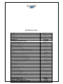
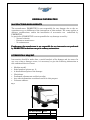
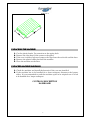
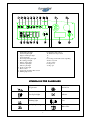
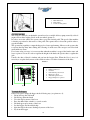
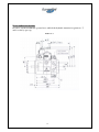
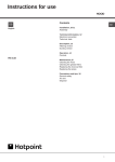
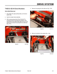
USER MANUAL
S 48B
ATTENZION! PLEASE READ THIS MANUAL BEFORE USING THE MACHINE
ING. O. FIORENTINI S.R.L.
INDUSTRIAL CLEANING MACHINES
INDEX
MACHINE DELIVERY
INTRODUCTION
TECHNICAL DESCRIPTION
GENERAL INFORMATION
MANUFACTURER RESPONSIBILITY
INTERVENTION REQUEST
TRANSPORT AND STOCKING
PACKED MACHINE HANDLING
UNPACKING THE MACHINE
UNPACKED MACHINE HANDLING
DESCRIPTION
DASHBOARD
SYMBOLS ON THE DASHBOARD
USING THE MACHINE
Braking System
Use
Hopper Discharge
Main Brush Height Regulation
Side Brush Height Regulation
How to unblock the machine
SAFETY, MAINTENANCE AND CONTROLS
GENERAL SEFATY RULES
DAILY MAINTENANCE RULES
Maintenance Plan
Diesel Engine PLan
Suction System
Main Brush Replacement
Side Brush Replacement
Filter Replacement
Shaker Filter Engine
Defects
CHECK
Safety Devices Check
Electric System Check
Braking System Check
Hydraulic System
Electric System
SPARE PARTS
2
pag. 3
3
4
5
5
5
6
6
6
6
7
7
8
9
9
9
10
10
10
11
12
12
13
13
13
13
14
14
14
14
15
16
16
16
16
17
18
19
MACHINE DELIVERY
AS SOON AS THE MACHINE IS DELIVERED, PLEASE CHECK THAT THERE
IS NOT ANY DAMAGE DUE TO TRANSPORT.
IN
CASE
OF
DAMAGE
OR
MISSING
PARTS,
PLEASE
ADVISE
IMMEDIATELY THE MANUFACTURER.
INTRODUCTION
THIS KIND OF SCRUBBER MACHINE CAN PERFECTLY WASH EVERY
KIND OF FLOOR FROM EVERY KIND OF DIRT WITH AN EXCELLENT RESULT.
THIS IS WHY THE MACHINE MUST ALWAYS BE USED IN A CORRECT
WAY AND MAINTAIN IT. PLEASE, READ CAREFULLY THIS USER AND
MAINTAINANCE MANUAL.
THE
MACHINE
MUST
ONLY
BE
CLEANING.
Please, keep this manual for any future reference
3
USED
FOR
THE
INDUSTRIAL
TECHNICAL DATA
LENGTH
WIDTH
HEIGHT
BRUSHES No.
SIDE BRUSH
MAIN BRUSH (1.200mm length)
WORKING WIDTH with right side brush
WORKING WIDTH with right and left side brush
WASTE TANK RECOVERY
FILTERING SURFACE
HYDRAULIC OIL TANK
WATER COOLING SYSTEM
FRONT AND REAR WHEEL DIMENSIONS
WEIGHT
POWER
SHAKER FILTER ENGINE 65 watt 7,8 A
SUCTION HYDRAULIC ENGINE
TRACTION HYDRAULIC ENGINE
MAIN BRUSH HYDRAULIC ENGINE
SIDE BRUSH HYDRAULIC ENGINE
VARIABLE DELIVERY PUMP
PISTON PUMP
HYDROGEAR
OPERATOR
MINIMUM U-TURN LANE
SERVICE BRAKE
PARKING BRAKE
FORWARD GEAR SPEED
REVERSE GEAR SPEED
MAX OVERWHELMING SLOPE
MAX OVERCOMING SLOPE FOR A U-TURN
CLEANED AREA (m²/h)
4
NOISE AT OPERATOR’S EAR
VIBRATIONS AT OPERATOR’S EAR
2280 mm
1470 mm
1500 mm
3
Ø 600 mm
Ø 380 mm
1500 mm
1800 mm
450 lt.
18 m2
65 lt.
5 lt.
4.00-8 16x6-8
1470 kg
BATTERY
7500rpm
OPM 20
OPM w315
OPM 50
OPM 100
APVC 20
C/28.8 –LBE/BCD
OSPC 100 ON
Man on board
2200 mm
hydraulic
Mechanical by lever
0 ÷12 Km/h
0 ÷12 Km/h
13 %
5% A 2 Km/h
18000m² /h
75 dBa
< 2.5 m/s²
GENERAL INFORMATION
MANUFACTURER RESPONSIBILITY
The manufacturer FIORENTINI is not responsible for any damage due to the noacquaintance or no-fulfilment of the instructions of this manual. The same applies to
changes, modifications, and/or the installation of accessories not authorized by
FIORENTINI.
In particular, FIORENTINI is not responsible for any damage caused by:
- Natural calamity
- Erroneous manoeuvres
- No maintenance
Furthermore, the manufacturer is not responsible for any intervention not performed
by FIORENTINI technicians except for ordinary maintenance.
INTERVENTION REQUEST
REQUEST
Intervention should be made after a careful analysis of the damage and its causes. In
any case, when a damage occurs, it is necessary to give the following information to
the authorized Service Centre:
•
•
•
•
•
•
•
Machine model;
Serial number (picture nr. 1);
A detailed description of the damage;
Check done;
Performed adjustments and their results;
Any other information considered useful for this purpose;
Customer address.
Fig. 1
Ing. O. Fiorentini
S.r.l. Piancaldoli (FI)
Mod. S 48B S.N.
Hz.
V
A
Kg 1470
MADE IN
5ITALY
CE
2009
W
GOODS TO BE RETURNED
In case of goods to be returned for warranty replacement, it is necessary to have a
written acceptance from
FIORENTINI technical department before sending them.
All defective parts must be carefully packed in order to avoid further damages during
transport.
Goods must be shipped ex-warehouse and followed by :
•
•
•
serial number of the equipment where they were installed on;
item code of the defective part;
detailed description of the defect and of the condictions where it happened.
In case of defective electric or electronic goods,
please return them separately from other materials,
in order to help us in dividing dangerous wastegoods
and recycle the (RAEE) as DER 2002/96/CEE LOW.
TRANSPORT AND STORAGE
PACKED MACHINE HANDLING
The machine is delivered in a special package, which is shown in picture nr. 2.
The gravity centre is indicated on the package with a black arrow. The pallet must be
forked in the middle of the side with the black arrow in order to avoid overturning.
The case should be handled with extreme caution.
It is forbidden to lay cases on each other.
6
Picture no. 2
UNPACKING THE MACHINE
1.
2.
3.
4.
5.
Cut the plastic bands. Pay attention to the spring back.
Remove the clips that fix the carton to the pallet.
If the case is made of plywood, remove the clips from the each side and the base.
Remove the plastic bands that hold the machine.
Place the machine on the floor.
UNPACKED MACHINE HANDLING
1. Check the machine and install the batteries if they are not installed.
2. If the machine has to be handled for a short transport, disconnect the battery
cables. It is recommended to pack the machine again in its original case if it has
to be handled for a longer transport.
CONTROLS DESCRIPTION
DASHBOARD
7
(22)
1.
2.
3.
4.
5.
6.
7.
8.
9.
10.
11.
13.
14.
Shaker filter pilot light
Suction fan pilot light
Engine air filter pilot light
Gasoil pilot light
Water temperature pilot light
Pre-starting pilot light
Engine oil pilot light
Generator pilot light
Indicator pilot light
Lights on pilot light
Hour counter
Suction fan and shaker filter switch
Blinking light switch
(23)
15. interruttore luci di lavoro
16. Windscreen wiper switch
17. 18. 19. Steering column with acustic signalling
20. Recovery tank
21. Key switch
22. flap closed
23. flap open
SYMBOLS ON THE DASHBOARD
Oil pressure
Suction fan
Gasoil pilot light
Indicator
Blinking light
Horn
Spark plug heating
Shaker filter
8
Water temperature
Hopper open
Flap closed
Hopper closed
Lights
Battery charger
Suction filters pilot light
Main brush lift up
Main brush lift down
USE OF THE MACHINE
Brake
The machine is equipped with parking and service brake (picture no. 4). The service brake is
hydraulic and is started by a pedal placed on the left of the footboard. The oil chamber is placed on
the forward pedal. The operator has to pull the lever up and do a 90° rotation in order to insert the
service brake.
Picture no. 4
9
1.
2.
3.
Hand brake lever
Dust gaskets
Screws for dust gaskets
Use of the machine
The sweeper is started by an hydraulic system based on a variable delivery pump started by a diesel
engine and an orbital engine placed on the rear wheel (picture 5).
In order to move the vehicle, the operator has to press the forward pedal. The speed of the machine
is directly proportional to the traverse of the pedal. The operator has to release the pedal in order to
stop the machine.
The operator has regularly to empty the hopper for a better performance. Moreover, the operator has
to activate the flap many times during the collecting of small waste. The sweeper can collect both
small and heavy waste.
For a better waste recovery, it is necessary that when the machine is stopped, the brush rotates and
leaves a print of 5-8 cm. In order to regulate the height of the brush, the operator has to regulate the
jack.
Usually, the dust collected is intaken and put into the hopper filter. When the floor is wet, it is
necessary to stop the fan by means of the switch in order to avoid the obstruction of the filter.
Picture 5
1.
2.
3.
4.
5.
6.
7.
Key switch
Parking brake lever
Gas lever
Central brush position lever
Flap lever position
Side brush position lever
Hopper lift up lever position
(7)
To empty the hopper
If necessary, please empty the hopper in the following way (see picture no. 6):
• Lift up and stop the side brush
• Lift and stop the main brush
• Close the flap by means of the lever
• Press the shaker filter switch for several seconds
• Lift the hopper up by means of the lever
• Lay the hopper onto the rubbish skip
• Open the flap for the waste discharge by means of the lever
• Lay down the hopper
10
Picture no. 6
Regulate the height of the main brush
• The operator ha sto regulate the aduste placed on the brushes jack
Regulate the height of the side brushes
• The operator has to regulate the knob under the brush arm
11
How to unblock the machine
In order to tow the machine the operator has to unblock the hydraulic transmission (picture no. 7)
and loose the by-pass cap.
Picture no. 7
12
SAFETY, MAINTENANCE AND CHECK
GENERAL SAFETY RULES
The rules listed below must be carefully followed in order to avoid damages to the
operator and/or the machine.
•
•
•
•
•
•
•
•
•
•
•
•
•
•
•
•
•
•
•
•
•
Read carefully the labels sticked on the machine and do not cover them for any
reason;
Do not mix detergents of different kind in order to avoid the development of
dangerous gases;
Do not use the machine in places with explosive substances;
Do not use the machine as a means of transport
Do not use acids which could damage the machine;
Do not intake flammable liquids for any reason
In case of fire, please use a powder extinguisher. Do not use water.
If the machine does not work in the correct way, please make sure that the defect is
not caused by a lack of ordinary maintenance. On the contrary, please immediately
contact FIORENTINI Service;
Before starting the machine again, please make sure that all fixed or removable
protections are in their position;
Do not wash the machine with corrosive substances or with water jets;
Do not keep the machine in an environment with a temperature < 3° C;
Avoid to leave the machine in a no-authorized place for the scrapping. In fact, the
machine is made of materials that must be recycled and disposed in authorized
centres;
The machine does not develop dangerous vibrations;
Keep always the machine far from kerbstones and drive slowly on surfaces with
holes;
Make sure that there are no people near the machine during the cleaning;
Do not start the machine if it is under maintenance;
Do not drive too fast while turning, in particular on sloping surfaces;
It is absolutely forbidden to touch
touch the inferior side of the machine during the
cleaning. If it is necessary, please keep the ignition key away from the dashboard;
The operator must carefully read this manual and do not use alcohol or medicines
before driving the machine;
The machine cannot
cannot be used in places with dangerous substances and in particular
with explosive atmospheres or with a bad microclimate;
microclimate;
Please, disconnect the battery when the machine is not working.
Italian
lian language.
Important: the operator has to have a sufficient knowledge of the Ita
13
Daily maintenance rules
While the operator is cleaning, maintaining the machine or replacing some of its parts,
the ignition key must not be in dashboard.
Maintenance plan
DAILY
• Clean the waste hopper
WEEKLY
• Check the water level of the starter battery
• Check the dust protection gasket
• Check the wear and tear of the main brush
• Check the hydraulic oil
EVERY 6 MONTHS
• Grease the bearings of the rear wheel
EVERY 2 YEARS
• Check the safety devices
• Check the electric system
Suction system
The suction system is based on a fan activated by an engine. It has the function to intake the dust
produced by the rotation of the brushes.
The suction power of the fan goes through the filters, which have the function to keep the dust.
Waste and dust are intaken into the recovery hopper.
In order to replace the filters, the operator has to remove the frames that hold the suction filters.
Moreover, the operator has to check that all the rubber gaskets are not damaged and well fixed in
order to avoid dust waste into the environment.
Main brush replacement
The main brush ha sto be replced when the bristles are 2-3 cm. Long.
Please follow the instructions listed below in order to replace the main brush:
1. Open the door which is on the bottom on the right side of the machine
2. Unscrew the screws which fix the dust protection rubber (picture no. 8)
3. Unscrew the both hexagonal screws which are on the right of the support in order to remove the
main brush
4. Remove the brush fron the left support
5. Please carefully check the direction of the main brush before setting it up
6. Set up again the right supporto f the main brush and the dust protection rubber
14
Picture no 8
1. Main brush
4. Hexagonal screws
Side brush replacement
The side brushes collect waste from the corners and carry it to the main brush.
The rotation of the main brush is started by an hydraulic engine, while the its regulation is activated
by a lever placed on the left side of the dashboard.
The main brush ha sto be in contact to the floor with the front side and not the rear side. In order to
replace the main brush, the operator has to unscrews no. 4 screws which are on the brush hub.
Afterwards, the operator has to remove the old main brush and set the new one up. Finally, the
operator has to tighten the 4 screws.
Filter replacement
Please follow the instructions below in order to replace the filter:
1. Open the bonnet
2. Remove the filter shaker sheets
3. Replace the filters and their gaskets
Do now the opposite instructions.
Engine for filter shaker
The engine for filter shaker makes the filters vibrate. In this way, the dust falls into the hopper.
If the engine breaks down, the operator has to replace the carbon brushes.
PROBLEMS AND DEFECTS
DEFECT
The vehicle runs slowly
PROBABLE CAUSE
A: the level of the hydraulic oil
is not sufficient
B:by-pass valve is open
C: the pressure of the traslation
circuiti is not sufficient
D: the filter of the traslation
circuiti is obstructed
15
SOLUTION
A: fill the hydraulic oil chamber
B: close the valve
C: check and regulate the
pressure
Brushes rotate slowly
Brushes rotate intermittent
The vehicle does not move
There is foam in the hydraulic
oil chamber
Dust flows through the sides of
the machine
Dust flows through the fan and
the bonnet
Not sufficient cleaning
E: the pump or the hydraulic
engine are defective
A: the engine rpm is low
B: the pump or the hydraulic
engines are defective
C: the pressure is not sufficient
A: increase the engine rpm
B: replace the pump or the
hydraulic engines
C: check and lightly increase
the pressure
A: the level of the hydraulic oil A: fill the hydraulic oil chamber
is not sufficient
B: suction filters are obstructed B: replace the filters
The by-pass valve is open
Close the valve
A: the level of the hydraulic oil A: fill the hydraulic oil chamber
is not sufficient
B: there is air in the suction
B: replace the hoses or make
sure that the fittings are well
hoses
fixed
A: the dust protection rubbers
A: replace the dust protection
are damaged
rubbers
B: the filter is obstructed
B: replace the filter shaker
because the filter shaker is
C: open the flap and check the
broken
right functioning
C: the flap is blocked and does
not open
A: the filter is damaged
A: replace the filter
B: the filter is not well set up
B: set up the filter correctly
A: the forward speed is too high A: decrease the forward speed
B: the main brush is too far
B: regulate the main brush
from the floor
position
C: the main brush is too worn
C: replace the main brush
CHECK
The machine has to be inspected by a technician who has to check the safety conditions and if the
machine is damaged or has visible defects:
• During the first start of the machine
• After modifications and repair
Check on safety devices
Check the efficiency of the safety devices every two years. The inspection has to be done by a
trained technician.
Every five years the machine ha sto be revised by a Fiorentini technician.
Check on the electric system
Every two years the electric system has to be checked. Burnt cables and not well fixed connections
have to be checked and replaced. Interventions have to be done by a trained technician.
Check on the braking system
16
The braking system has to be checked every 3 months
HYDRAULIC SYSTEM
17
18
ELECTRIC SYSTEM
19
Mat. n.
Serial no.
Nr. de serie
_____________________
Data di spedizione
Date of shipment
Date de spedition
_____________________
Distributed by:
ING. O. FIORENTINI s.r.l.
“THE BEST IN FLOOR MACHINES”
FILIALI:
20132 MILANO – Fax. 02/2592779
Via Palmanova 211/a – Tel. 02/27207783 - 2564810
00155 ROMA – Fax. 06/22754075
Via Carlo Carrà 13 – Tel. 06/22754040-2275060
STABILIMENTO:
50030 PIANCALDOLI (FI) – Fax. 055/817144
Loc. Rombola – Tel. 055/8173610
20