1
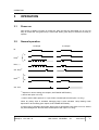
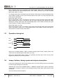
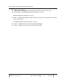
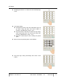
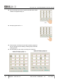
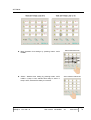
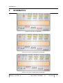
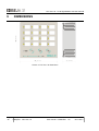
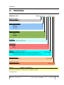
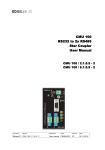
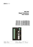
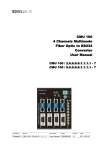
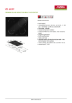
LSU 100 / 16 Local Signalization Unit User manual LSU 100 / 16 Company: Device: Ediseja 21 LSU 100 / 16 Document: Code: User manual LSUMUE01 Version: Date: V6 05.01.2014 LSU 100 / 16 - Local Signalization Unit User manual Content 1 PREFACE.......................................................................................................3 2 DESCRIPTION...............................................................................................6 3 OPERATION...................................................................................................7 3.1 Power on............................................................................................................................. 7 3.2 Normal operation................................................................................................................ 7 3.3 Operation during test......................................................................................................... 8 3.4 Lamps, buttons, binary inputs and outputs description.................................................9 4 SETTINGS....................................................................................................10 5 SCHEMATICS..............................................................................................17 6 INSTALLATION............................................................................................18 7 COMMISSIONING AND MAINTENANCE...................................................20 7.1 COMMISSIONING.............................................................................................................. 20 7.2 MAINTENANCE................................................................................................................. 20 8 TECHNICAL DATA......................................................................................21 9 DIMENSIONS...............................................................................................23 10 ORDERING.................................................................................................24 Page: Company: Device: 2 Ediseja 21 LSU 100 / 16 Document: Code: User manual LSUMUE01 Version: Date: V6 05.01.2014 PREFACE 1 PREFACE Liability statement We have checked the contents of this manual to ensure that the descriptions of both hardware and software are as accurate as possible. However, deviations may occur so that no liability can be accepted for any errors or omissions contained in the information given. The contents of this manual will be checked in periodical intervals, corrections will be made in the following editions. We reserve the right to make technical improvements without notice. Contact If you have any questions or comments related to this product please contact us on: Ediseja 21 d.o.o. Drenov Gric 175 1360 Vrhnika Slovenia – EU Tel: ++386 (1) 75 05 275 Email: [email protected] www.ediseja21.com Copyright Copyright © Ediseja 21, 2013. All rights reserved. Explanation of the symbols Read the instructions! Device was tested with 2,5 kV AC voltage to check the device insulation. Device ground terminal. Waste Electrical and Electronic Equipment (WEEE) Directive 2002/96/EC; the affixed product label indicates that you must not discard this electrical/electronic product in domestic household waste. Company: Device: Ediseja 21 LSU 100 / 16 Document: Code: User manual LSUMUE01 Version: Date: V6 05.01.2014 Page: 3 LSU 100 / 16 - Local Signalization Unit User manual Warnings In this paper the following terms are used: Danger indicates that death, severe personal injury or substantial property damage will result if proper precautions are not taken. Warning indicates that death, severe personal injury or substantial property damage can result if proper precautions are not taken. Caution indicates that minor personal injury or property damage can result if proper precautions are not taken. This particularly applies to damage on or in the device itself. General information These paper contain the information that is necessary for the proper and safe operation of the described devices. This paper is intended for technically qualified personnel. Warning! Hazardous voltage is present inside the device during operation. Disregarding of safety rules can result in severe personal injury or property damage. Only qualified personnel may work with described devices after being familiar with warnings and safety notices in this paper and other safety regulations. Warning! Device must operate completely assembled! Device must be used as described. No modifications of the device should be made. Warning! Do not open device while it is energized! Hazardous voltage is present inside the device. Disconnect all connectors before opening! Page: Company: Device: 4 Ediseja 21 LSU 100 / 16 Document: Code: User manual LSUMUE01 Version: Date: V6 05.01.2014 PREFACE Warning! If device is damaged disconnect it from power supply! Send it to the manufacturer for inspection. Warning! Connect to earth before attaching power supply! Company: Device: Ediseja 21 LSU 100 / 16 Document: Code: User manual LSUMUE01 Version: Date: V6 05.01.2014 Page: 5 LSU 100 / 16 - Local Signalization Unit User manual 2 DESCRIPTION LSU100 device is intended for local signalization in power distribution substations. It is also called alarm annunciator. Power supply and binary inputs are made for standard voltages in substations; 48 V DC, 110 V DC or 220 V DC depends on ordering. Device has 16 signal binary inputs (»DI1-DIn«), which controls dependent lamp (lamp1-n). Speed and mode of lamp flashing depends on setting and can be changed by buttons on front side of device. Two modes of operation and four flashing LED time can be set. First operation mode is latched until acknowledged, second mode just follow the binary input. In first mode following flash LED time can be set: 0.5, 0.75, 1 and 1.5 s. Red/green lamp on front side of device has a function of visual inspection of device operation. Device with option »A« has additional binary input. Activation of this input has equal effect as pressing button »ACK LAMP«. Device with option »O« has two additional binary outputs; »DO1« and »DO2«. »DO1« is intended for controlling external lamp. »DO2« is intended for controlling external horn. Page: Company: Device: 6 Ediseja 21 LSU 100 / 16 Document: Code: User manual LSUMUE01 Version: Date: V6 05.01.2014 OPERATION 3 OPERATION 3.1 Power on After power is applied, red lamp is turned ON. After all LEDs are illuminated one by one red lamp is turned OFF and green lamp is turned ON. When green lamp is ON device is ready to operate. 3.2 Normal operation 1. example 2. example DI A lamp(1) B DO1(1) (2) ack. lamp(3) A DO2(1)(2) B ack. horn (1) depends on device setting (see chapter „SOFTWARE SETTINGS“) (2) device with option »O« only (3) button »ACK LAMP« pressed or input »DIA« activated (device with option »A« only) When any binary input is activated, belonging lamp is also activated. Lamp flashing mode depends on device setting (see chapter „SOFTWARE SETTINGS“): A) when input is activated, lamp lights. When input is deactivated, lamp lights no more, without any acknowledgement. No DOs are activated (device with option »O« only). Company: Device: Ediseja 21 LSU 100 / 16 Document: Code: User manual LSUMUE01 Version: Date: V6 05.01.2014 Page: 7 LSU 100 / 16 - Local Signalization Unit User manual B) (1. example) when input is activated, lamp start to flash. When input is deactivated, lamp flashes until lamps are acknowledged (button »ACK LAMP« pressed or input »DIA« activated (device with option »A« only)) (2. example) when input is activated, lamp start to flash. When lamps are acknowledged (button »ACK LAMP« pressed or input »DIA« activated (device with option »A« only) lamp lights until binary input is deactivated. (device with option »O« only) DO1 normal position is OFF. At activation of any binary input set at B mode, binary output DO1 starts to alternate from OFF to ON position and vice versa. Alternation time depends on LEDs flashing time setting. When lamps are acknowledged (button »ACK LAMP« pressed), DO1 goes to OFF position no matter of binary input states. (device with option »O« only) DO2 normal postion is OFF. At activation of any binary input set at B mode, binary output DO2 goes to ON position. When horn is acknowleged (button »ACK HORN« pressed), DO2 goes to OFF position no matter of binary input states. 3.3 Operation during test test DO1(2) lamp(1) A B DO2(2) When test is activated (button »TEST« pressed) all lamps lights. Binary outputs »DO1« and »DO2« are also activated (device with option »O« only). When test is deactivated (button »TEST« not pressed) all lamps start to flash as they were triggered by binary input in normal operation. 3.4 Lamps, buttons, binary inputs and outputs description Lamps are numbered from left to right (looking from front side). Binary inputs are numbered from left to right (looking from back side). Additional two colour lamp »POWER SUPPLY / ERROR« signalise state of device. Red lamp means device is starting or device is not operating correctly. Green lamp means device is fully operational. On front side there are three buttons: Page: Company: Device: 8 Ediseja 21 LSU 100 / 16 Document: Code: User manual LSUMUE01 Version: Date: V6 05.01.2014 Lamps, buttons, binary inputs and outputs description »TEST« - testing device »ACK LAMP« - acknowledge active lamps and DO1 (device with option »O« only) »ACK HORN« - acknowledge DO2 (device with option »O« only) Additional input (device with option »A« only): »DIA« – external acknowledge of lamps; activation of that input has equal effect as pressing button »ACK LAMP«. Two additional outputs (device with option »O« only): Company: »DO1« – external lamp control, active until lamp acknowledge »DO2« – external horn control, active until horn acknowledge Device: Ediseja 21 LSU 100 / 16 Document: Code: User manual LSUMUE01 Version: Date: V6 05.01.2014 Page: 9 LSU 100 / 16 - Local Signalization Unit User manual 4 SETTINGS Setting procedure: Press and hold approximately 3 s. button All lamps goes ON for 1 s. »ACK HORN« for Device is now in set lamp flashing speed mode. All lamps are flashing except first, second, third or fourth row column. Which column is ON depends on current setting. Column which is ON marks the speed of lamp is flashing: first column ON - flashing on 0,5 s second column ON - flashing on 0,75 s third column ON - flashing on 1 s fourth column ON - flashing on 1,5 s. Change the speed of lamp flashing with button »ACK HORN«. Page: Company: Device: 10 Ediseja 21 LSU 100 / 16 Document: Code: User manual LSUMUE01 Version: Date: V6 05.01.2014 SETTINGS All lamps goes ON for 1 s. Device is now in set lamp logic mode. Lamp logic setting: lamp flashing means, that when dependent input will go active, lamp will flash until »ACK LAMP« is pressed („OPERATION„ (»lamp – B«)) lamp ON means, that lamp wil follow the input state; active inpute lamp ON, non active input lamp OFF (chapter „OPERATION„ (»lamp – A«)) lamp OFF means lamp we are currently set (lowest right). Move to lamps by pressing button »ACK HORN«. One lamp logic setting acknowlege with button »ACK LAMP«. Company: Device: Ediseja 21 LSU 100 / 16 Document: Code: User manual LSUMUE01 Version: Date: V6 05.01.2014 Page: 11 LSU 100 / 16 - Local Signalization Unit User manual When all lamps logic are set press and hold button »ACK HORN« for approximately 3 s. All lamps goes ON for 1 s. First left lamp is ON and it marks the led (binary inputs) to be set. Last righ lamp is flashing. Flashing lamp marks the setting position. Set time delay for each lamp according to the pictures: Page: Company: Device: 12 Ediseja 21 LSU 100 / 16 Document: Code: User manual LSUMUE01 Version: Date: V6 05.01.2014 SETTINGS Move between time settings by pressing button »ACK HORN«. Select / deselect time setting by pressing button »ACK LAMP«. If lamp is ON, selected time delay is active. If lamp is OFF, selected time delay is not active. Company: Device: Ediseja 21 LSU 100 / 16 Document: Code: User manual LSUMUE01 Version: Date: V6 05.01.2014 Page: 13 LSU 100 / 16 - Local Signalization Unit User manual Move between lamps by pressing button »TEST«. When time delays for all lamps are set press and hold button »ACK HORN« for approximately 3 s. All lamps goes ON for 1 s. Device goes into reset. After reset device is in operating mode. Page: Company: Device: 14 Ediseja 21 LSU 100 / 16 Document: Code: User manual LSUMUE01 Version: Date: V6 05.01.2014 SCHEMATICS 5 SCHEMATICS Picture 1: LSU 100 / 16 schematic Picture 2: LSU 100 / 16 (with option A) schematic Picture 3: LSU 100 / 16 (with option O) schematic Company: Device: Ediseja 21 LSU 100 / 16 Document: Code: User manual LSUMUE01 Version: Date: V6 05.01.2014 Page: 15 LSU 100 / 16 - Local Signalization Unit User manual 6 INSTALLATION Warning! Hazardous voltage is present inside the device during operation. Disregarding of safety rules can result in severe personal injury or property damage. Only qualified personnel may work with described devices after being familiar with warnings and safety notices in this paper and other safety regulations. Following instruction must be taken into consideration: The device must be accessible to qualified personnel only. The device is permitted to operate in enclosed housing or cabinet only. The device location must be vibration-free. The admisible operating temperature must be observed. Check the device for damage at unpacking. If device is damaged it must not be installed, but it should be send to the manufacturer for repair. The device should not be opened. Attach ground wire before attaching power supply. Device must be grounded during operation! Single core or stranded wire 0.5 – 2.5 mm 2 must be used for power supply connection. If stranded wire is used, ferrules must be used to prevent fraying. Recommended stripping lenght is 5 mm. Thickness of the mounting plate should be 1 to 2,5 mm. The device should be mounted in recommended cut-out hole (see picture). Page: Company: Device: 16 Ediseja 21 LSU 100 / 16 Document: Code: User manual LSUMUE01 Version: Date: V6 05.01.2014 INSTALLATION Picture 4: LSU 100 / 16 recommended cut out Picture 5: LSU 100 / 16 left. installation, right: deinstallation Company: Device: Ediseja 21 LSU 100 / 16 Document: Code: User manual LSUMUE01 Version: Date: V6 05.01.2014 Page: 17 LSU 100 / 16 - Local Signalization Unit User manual Picture 6: LSU 100 / 16 inserted papers dimensions Page: Company: Device: 18 Ediseja 21 LSU 100 / 16 Document: Code: User manual LSUMUE01 Version: Date: V6 05.01.2014 COMMISSIONING AND MAINTENANCE 7 COMMISSIONING AND MAINTENANCE 7.1 COMMISSIONING Warning! Hazardous voltage is present inside the device during operation. Disregarding of safety rules can result in severe personal injury or property damage. Only qualified personnel may work with described devices after being familiar with warnings and safety notices in this paper and other safety regulations. Following instruction must be taken into consideration: Device must operate completely assembled! Device must be used as described. No modifications of the device should be made. Attach ground wire before attaching power supply. Device must be grounded during operation! Check if the power supply voltage complies with device operation voltage. Do not open device while it is energized! Hazardous voltage is present inside the device. 7.2 MAINTENANCE Device is maintenance-free. Do not use liquids for cleaning the unit. Use water moisturised mop. Disconnect all connectors before cleaning. Company: Device: Ediseja 21 LSU 100 / 16 Document: Code: User manual LSUMUE01 Version: Date: V6 05.01.2014 Page: 19 LSU 100 / 16 - Local Signalization Unit User manual 8 TECHNICAL DATA Power supply 88 – 250 V DC Input voltage Power consumption 88 V DC 34 mA 3W 250 V DC 12 mA 3W Voltage dips > 20 ms Connector type „MSTB“ Phoenix 2pin Power supply wire Ground wire crossection 0.5 – 2.5 mm2 type single or stranded wire voltage rating 500 V colour depends on used standard crossection Cu flat, 40 mm 2 colour yellow-green or natural (non isolated) Binary input Input voltage Input current 110 V DC 88 – 121 V DC 220 V DC 176 – 250 V DC 110 V DC 1 mA 220 V DC 1 mA „MSTB“ Phoenix Connector type Wire crossection 0.5 – 2.5 mm2 type single or stranded wire voltage rating 500 V colour depends on used standard 0-65535 ms, 16 ms step, ± 5 % Time delay setting Binary output (Device with option „O“ only) 440 V AC Max breaking voltage AC 5 A at 250 V 5 A at 32 V (resistive bourden) Max current DC 1,3 A at 48 V (resistive bourden) 0,4 A at 110 V (resistive bourden) 0,35 A at 220 V (resistive bourden) Connector type Page: Company: Device: 20 Ediseja 21 LSU 100 / 16 screw type „MSTB“ Phoenix 3 pin Document: Code: User manual LSUMUE01 Version: Date: V6 05.01.2014 TECHNICAL DATA Binary output Wire (Device with option „O“ only) crossection 0.5 – 2.5 mm2 type single or stranded wire voltage rating 500 V colour depends on used standard Operation Flash LED time programmable 0.5, 0.75, 1 or 1.5 s Time to trigger LED > 13 ms Device 0,75 kg Weight Dimensions 160 mm 57,5 mm Temperature range -10 °C to + 55 °C Humidity operating up to 95 % (noncondensing) Enclosure Company: 160 mm Material Al IP 20 Class I Overvoltage category II Altitude up to 2000 m Device: Ediseja 21 LSU 100 / 16 Document: Code: User manual LSUMUE01 Version: Date: V6 05.01.2014 Page: 21 LSU 100 / 16 - Local Signalization Unit User manual 9 DIMENSIONS Picture 7: LSU 100 / 16 dimensions Page: Company: Device: 22 Ediseja 21 LSU 100 / 16 Document: Code: User manual LSUMUE01 Version: Date: V6 05.01.2014 ORDERING 10 ORDERING ORDERING CODE: LSU100 / c . c . c . c . c . c - c . c Number of lamps: number of lamp* ............................................................... 16 Power supply voltage: 24 V DC...................................................................................... 1* 48 V DC...................................................................................... 2 110 V DC.................................................................................... 3 220 V DC.................................................................................... 4 Binary input voltage: 24 Vdc............................................................................................... 1 48 Vdc............................................................................................... 2 110 Vdc............................................................................................. 3 220 Vdc............................................................................................. 4 Enclosure: 160 x 160 mm panel mount ................................................................... V Lamp colour: yellow ........................................................................................................... Y red ................................................................................................................ R green ............................................................................................................ G Options: (see chapter „Schematics“) without additional options .................................................................. (leave empty) additional binary input for remote lamp acknowledgement ................................ A two additional binay outputs for external lamp and horn control ........................ O Software Version: software version ...................................................................................... (leave empty) Software Revision: software revision ............................................................................................ (leave empty) Example: LSU100 / 16.3.3.V.R.O is 16 channel local signalization unit, with 110 V DC power supply, 110 V DC binary inputs, 160x160 mm panel mount enclosure, red lamps, with two additional outputs * in development Company: Device: Ediseja 21 LSU 100 / 16 Document: Code: User manual LSUMUE01 Version: Date: V6 05.01.2014 Page: 23 LSU 100 / 16 - Local Signalization Unit User manual ** if 32 lamps are needed, see LSU 110 / 32 user manual Contact: Ediseja 21, razvoj elektronskih naprav, d.o.o. Drenov Gric 175 1360 Vrhnika Slovenia – EU Tel: ++386 (1) 75 05 275 [email protected] www.ediseja21.com Page: Company: Device: 24 Ediseja 21 LSU 100 / 16 Document: Code: User manual LSUMUE01 Version: Date: V6 05.01.2014